Abus SG1660 User manual

SG1650SG1660
Kombisignalgeber
Installationsanleitung
Flash and sounder
Installation Guide .............................................................5
Sirène d'alarme
Instructions d’installation..................................................9
Segnalatore combinato
Istruzioni per installazione .............................................13
Combisignaalgenerator
Installatie-instructies ......................................................17
Kombi-alarmsirene
Installationsvejledning....................................................21

2
Vorwort
Sehr geehrte Kundin, sehr geehrter Kunde,
wir bedanken uns für den Kauf dieses akustischen, bzw. optisch-
akustischen Kombisignalgebers. Mit diesem Gerät haben Sie ein Produkt
erworben, das nach dem heutigen Stand der Technik gebaut wurde.
Dieses Produkt erfüllt die Anforderungen der geltenden europäischen und
nationalen Richtlinien. Die Konformität wurde nachgewiesen, die
entsprechenden Erklärungen und Unterlagen sind beim Hersteller
hinterlegt. Um diesen Zustand zu erhalten und einen gefahrlosen Betrieb
sicherzustellen, müssen Sie als Anwender diese Montageanleitung
beachten!
Hinweise
Um eine Manipulation des Kombisignalgebers zu vermeiden, sollte das
Produkt außerhalb des Handbereiches (mindestens 3 Meter Montagehöhe)
montiert werden.
Bitte beachten Sie außerdem die lokalen gesetzlichen Bestimmungen. In
einigen europäischen Ländern ist der Einsatz von Sirenen im
Außenbereich verboten oder die maximale Alarmdauer ist reduziert. Im
Zweifelsfall informieren Sie sich bei Ihren lokalen Behörden.
Durch unsachgemäße oder unsaubere Installationsarbeiten kann es zu
Störungen oder Fehlfunktionen kommen. Lesen Sie sich daher diese
Anleitung genau durch. Berücksichtigen Sie die Angaben zur Schutzart und
achten Sie bei der Installation der Anlage auf die genaue Bezeichnung der
verwendeten Leitungen und Komponenten.
Hauptmerkmale
•Akustischer, bzw. optisch-akustischer Kombisignalgeber
geeignet für Innen- und Außenmontage
•Stabiles wetterfestes Gehäuse aus Aluminium
•Innenschutzgitter
•Extrem lautes Sirenenhorn
•Weithin sichtbarer Xenon-Blitz
•Schutz gegen Sabotage und Wandabriss

3
Beschreibung
1 2 2
2 2
3 4 5 6 7
8
9
Masse Anschluss Blitz
12V Anschluss Blitz (SG1660)
Masse Anschluss Sirene
12V Anschluss Sirene
Nicht belegt
Deckelkontakt NC
Deckelkontakt NC
Wandabrisskontakt (intern)
1 Gehäusedeckel
2 Montagelöcher
3 Sirene
4 Befestigung
Schutzhaube
5 Befestigung
Gehäusedeckel
6 Deckelkontakt
7 Befestigung
Wandabrisskontakt
8 Schraubklemmleiste
9 Schutzhaube

4
Installation
1. Benutzen Sie die Rückseiten des Signalgebergehäuses zum
Markieren der Befestigung (2). Bohren Sie dann die Haltelöcher.
2. Führen Sie das Anschlusskabel durch die vorgesehene Öffnung.
3. Befestigen Sie die Rückwand und den Abrisskontakt (7) an der
Wand.
4. Stellen Sie die Verbindungen an der Klemmleiste (8) wie
beschrieben her.
5. Setzen Sie die Schutzhaube (9) und den Gehäusedeckel (1) wieder
auf und ziehen Sie die Halteschrauben fest.
ACHTUNG: Achten Sie beim Anschluss des Signalgebers
auf polrichtige Verbindungen, da es ansonsten zu
irreversiblen Beschädigungen des Blitzlichts kommen
kann.
Anschlüsse
Verwenden Sie ausschließlich abgeschirmte und geerdete Leitungen.
Verbinden Sie die Anschlüsse für Blitz und Sirene mit den entsprechenden
Steuer-, bzw. Schaltausgängen Ihrer Zentrale. Achten Sie auf die
Gesamtstromaufnahme. Zusätzlich können Sie den Deckelkontakt mit in
die Sabotagelinie Ihrer Zentrale einschleifen.
Technische Daten
Spannungsversorgung 10 – 15 VDC
Max. Stromaufnahme (ohne Blitz) 340mA
Max. Stromaufnahme (mit Blitz) 750mA
Akustische Alarmierung 110dB @ 1m
Schutzart IP34
Betriebsart -25 +55 C°
Maße (BxHxT) 190 x 310 x 120 mm
Gewicht mit Blitz (ohne Blitz) 1850g (1700g)
Der Hersteller behält sich vor technische Änderungen ohne
Vorankündigung durchzuführen.

SG1650SG1660
Flash and sounder
Installation guide
Kombisignalgeber
Installationsanleitung .......................................................1
Sirène d'alarme
Instructions d’installation..................................................9
Segnalatore combinato
Istruzioni per installazione .............................................13
Combisignaalgenerator
Installatie-instructies ......................................................17
Kombi-alarmsirene
Installationsvejledning....................................................21

6
Preface
Dear Customer,
Thank you for purchasing this acoustic or optical/acoustic flash and
sounder equipment. You made the right decision in choosing this state-of-
the-art technology, which complies with the current standards of domestic
and European regulations. The CE has been proven and all related
certifications are available from the manufacturer upon request. To
maintain this status and to guarantee safe operation, it is your obligation to
observe these operating instructions.
Notes
To prevent manipulation of the flash and sounder, install the product out of
arm’s reach (at least 3 meters high).
Additionally, please take local legislation into consideration. In some
European countries, the use of sirens externally is forbidden, or the
maximum alarm duration is restricted. In case of doubt, ask your local
authorities for information.
Improper or careless installation work may lead to faults or malfunctioning.
You should therefore read these instructions carefully. Observe the
protection type specifications and follow the installation instructions for the
lines and components used precisely.
Main features
•Acoustic or optical/acoustic flash and sounder, suitable for indoor
and outdoor installation
•Strong, weatherproof aluminium casing
•Interior protection grille
•Extremely loud siren horn
•Xenon flash visible over large areas
•Protection against tampering and removal

7
Description
1 2 2
2 2
3 4 5 6 7
8
9
Ground contact – flash (SG1660)
12V contact – flash (SG1660)
Ground contact – sounder
12V contact – sounder
Not used
Cover contact – NC
Cover contact – NC
Removal contact (internal)
1 Housing cover
2 Mounting screw
holes
3 Sounder
4 Fastening
Protective cover
5 Fastening
Housing cover
6 Cover contact
7 Fastening
Removal contact
8 Screw terminal
block
9 Protective cover

8
Installation
1. Use the back of the flash and sounder case as a template for marking
the drill holes (2). Drill the holes for the fixing screws.
2. Pull the connector cable through the opening provided.
3. Fix the rear of the casing and the removal contact (7) to the wall.
4. Connect the cables to the terminal block (8) as described .
5. Replace the protective cover (9) and the casing cover (1) and tighten
the fixing screws.
IMPORTANT: Make sure you connect the cables to the
right polarity, otherwise the flashlight may be irreparably
damaged.
Connections
Use only shielded and grounded cables.
Connect the flash and sounder cables to the corresponding control or
switching outputs of your alarm system. Check the total power
consumption. You can also incorporate the cover contact into the tamper
line of your alarm system.
Technical data
Voltage supply 10–15 V DC
Max. power consumption (without
flash)
340mA
Max. power consumption (with
flash)
750mA
Acoustic alarm 110dB @ 1m
Protection type IP34
Operating temperature -25 to +55°C
Dimensions (WxHxD) 190 x 310 x 120 mm
Weight with flash / without flash 1,850g / 1,700g
The manufacturer reserves the right to make technical modifications
without prior notice.

9
SG1650SG1660
Sirène d’alarme
Instructions d’installation
Kombisignalgeber
Installationsanleitung....................................................... 1
Flash and sounder
Installation Guide............................................................. 5
Segnalatore combinato
Istruzioni per installazione ............................................. 13
Combisignaalgenerator
Installatie-instructies...................................................... 17
Kombi-alarmsirene
Installationsvejledning ................................................... 21

10
Préface
Chère cliente, cher client,
Nous vous remercions d’avoir porté votre choix sur cette sirène d'alarme
acoustique ou visuelle et acoustique. Par l’achat de ce produit, vous
disposez maintenant d’un appareil faisant appel à une technologie de
pointe. Ce produit est conforme aux exigences des directives européennes
et nationales en vigueur. La conformité de ce produit a été prouvée. Les
déclarations et documents correspondants ont été déposés chez le
fabricant. Pour que cette conformité persiste et qu’un fonctionnement en
toute sécurité puisse être assuré, lire attentivement ces instructions de
montage !
Remarques
Pour éviter toute manipulation de la sirène d’alarme, la monter hors
d’atteinte (hauteur de montage : au moins 3 m au dessus du sol).
De plus, tenir compte des dispositions légales en vigueur dans le pays
correspondant. Dans certains pays d’Europe, l’utilisation de sirènes à
l’extérieur est interdite ou la durée d’alarme maximale est limitée. En cas
de doute, s’informer ce faisant auprès des autorités locales.
Des travaux d'installation non conformes ou incorrects risquent d'être à
l'origine de perturbations ou d’anomalies de fonctionnement. Lire donc
attentivement l’intégralité de la présente notice. Tenir compte des
informations sur l’indice de protection et, lors de l’installation du système,
de la désignation exacte des câbles et des composants utilisés.
Principales caractéristiques
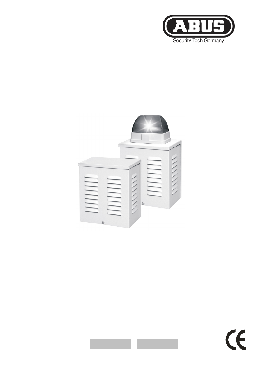
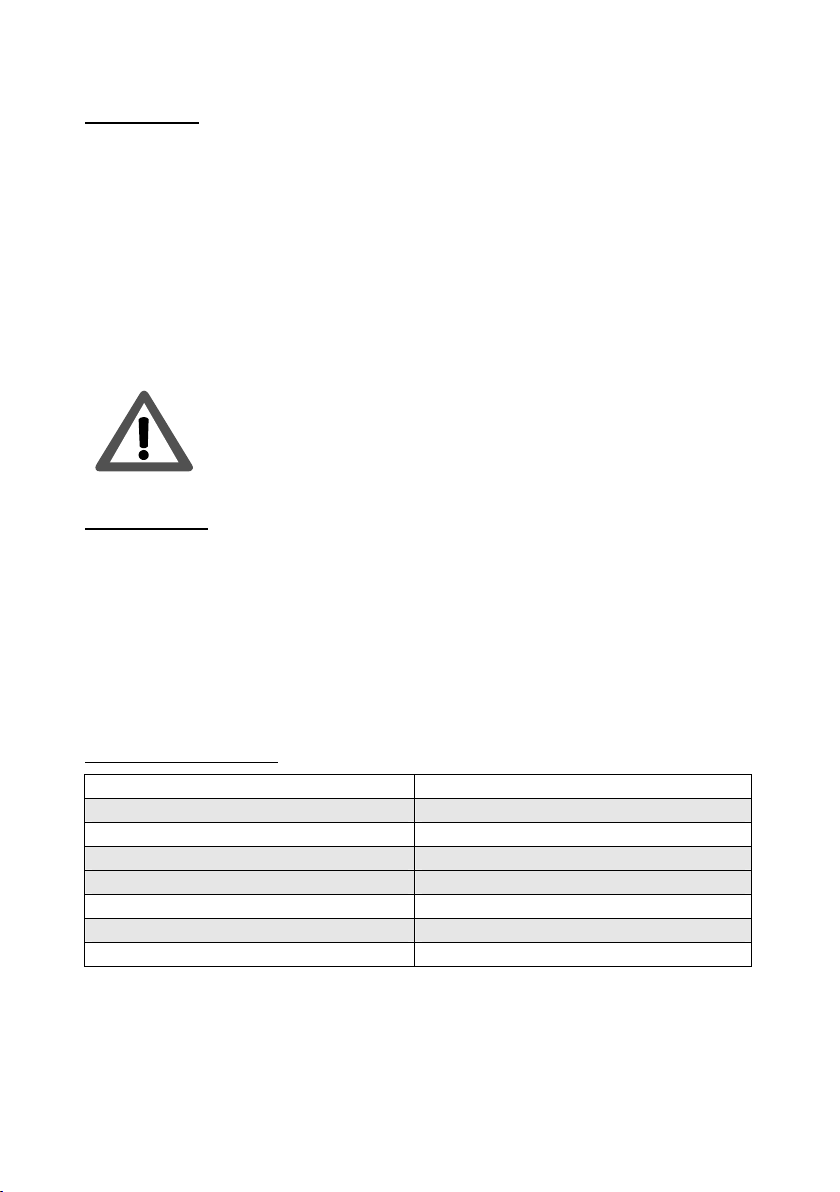
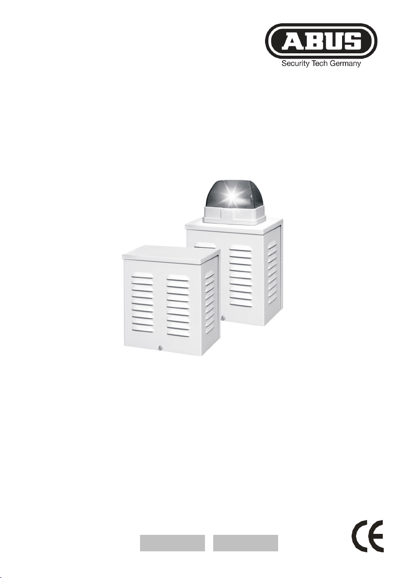
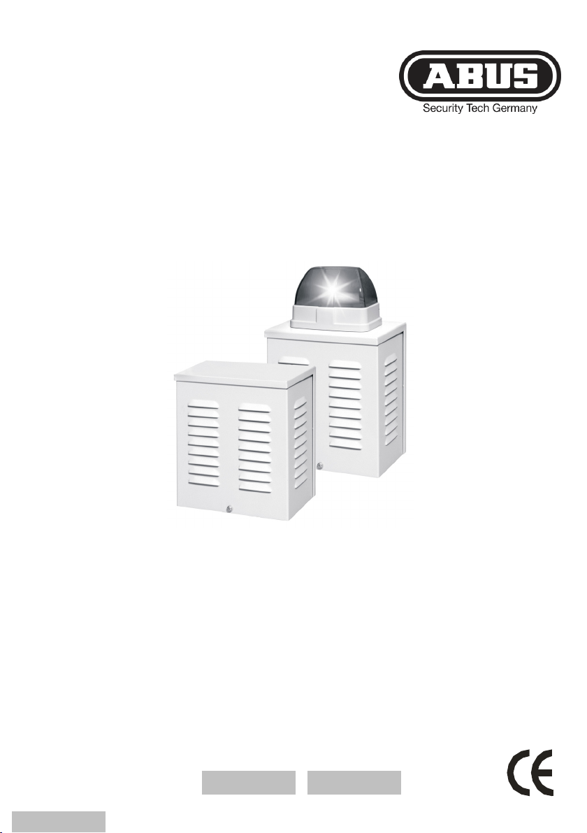
•Sirène d'alarme acoustique ou visuelle et acoustique
idéale pour un montage en intérieur et en extérieur
•Boîtier en aluminium stable et résistant aux intempéries
•Grille de protection interne
•Avertisseur sonore extrêmement puissant
•Flash au xénon longue portée
•Protection anti-sabotage et anti-arrachement

11
Description
1 2 2
2 2
3 4 5 6 7
8
9
Connexion neutre du flash (SG1660)
Connexion 12 V du flash (SG1660)
Connexion neutre de la sirène
Connexion 12 V de la sirène
Libre
Contact du couvercle NC
Contact anti-arrachement (interne)
1 Couvercle du boîtier
2 Trous de montage
3 Sirène
4 Fixation du
capuchon
protecteur
5 Fixation du
couvercle du boîtier
6 Contact du
couvercle
7 Fixation du contact
anti-arrachement
8 Réglette de
borniers à vis
9 Capuchon de
protection

12
Installation
1. Utiliser la face arrière du boîtier de la sirène pour marquer les trous de
fixation (2). Percer ensuite les trous de fixation.
2. Introduire le câble de raccordement par l’ouverture prévue à cet effet.
3. Fixer la face arrière et le contact anti-arrachement (7) au mur.
4. Raccorder, comme indiqué, les bornes de la barrette (8).
5. Remettre le capuchon protecteur (9) et le couvercle du boîtier (1), puis
serrer fermement les vis de fixation.
ATTENTION: Lors du raccordement de la sirène d'alarme,
faire attention à la polarité. Dans le cas contraire, le flash
risquerait d’être endommagé de manière irréversible.
Raccordements
Utiliser uniquement des câbles blindés et mis à la terre.
Raccorder le flash et la sirène aux sorties de commande et commutables
correspondantes de la centrale. Tenir compte de la consommation totale.
En complément, le contact du couvercle peut être relié à la ligne anti-
sabotage de la centrale d’alarme.
Fiche technique
Alimentation 10 – 15 V c.c.
Consommation maxi. (sans flash) 340 mA
Consommation maxi. (avec flash) 750 mA
Avertisseur sonore 110 dB à 1 m
Indice de protection IP34
Mode de fonctionnement -25 +55 C°
Dimensions (LxHxP) 190 x 310 x 120 mm
Poids flash inclus (sans flash) 1850 g (1700 g)
Sous réserve de modifications techniques sans préavis.

SG1650SG1660
Segnalatore combinato
Istruzioni per l‘installazione
Kombisignalgeber
Installationsanleitung .......................................................1
Flash and sounder
Installation Guide .............................................................5
Sirène d'alarme
Instructions d’installation..................................................9
Combisignaalgenerator
Installatie-instructies ......................................................17
Kombi-alarmsirene
Installationsvejledning....................................................21

14
Prefazione
Egregio Cliente,
La ringraziamo per aver acquistato questo segnalatore ottico-acustico. In
questo modo Lei ha acquistato un prodotto realizzato secondo l'attuale
stato della tecnica. Questo prodotto risponde ai requisiti richiesti dalle
vigenti direttive europee e nazionali. La conformità è stata comprovata e le
dichiarazioni e la documentazione relative sono depositate presso la ditta
produttrice. Al fine di preservare tale stato e garantire un corretto
funzionamento, in qualità di utente, Lei è tenuto ad osservare queste
istruzioni per il montaggio!
Avvertenze
Al fine di evitare una manipolazione dell’impianto segnalatore combinato, il
prodotto dovrebbe essere montato fuori portata (almeno a 3 m di altezza).
Osservare, inoltre, le disposizioni legali locali.. In alcuni paesi europei,
l’impiego di sirene all’esterno è vietato oppure la durata massima
dell’allarme è ridotta. In caso di incertezza, richiedere informazioni presso
le autorità locali.
Interventi di installazione non corretti possono causare guasti e
malfunzionamenti. Pertanto, leggere le presenti istruzioni con cura.
Osservare le indicazioni relative al tipo di protezione e all'atto
dell'installazione dell’impianto prestare particolare attenzione alle esatte
denominazioni delle linee e dei componenti utilizzati.
Caratteristiche principali
•segnalatore acustico o ottico-acustico, ideale per applicazioni indoor
e outdoor.
•scatola in alluminio solida resistente agli agenti atmosferici
•griglia di protezione interna
•sirena molto forte
•Lampeggiatore Xenon visibile a distanza
•Protezione da manomissione e distacco da parete

15
Descrizione
1 2 2
2 2
3 4 5 6 7
8
9
Lampeggiatore collegato a massa (SG1660)
Lampeggiatore collegato a 12V (SG1660)
Sirena collegata a massa
Sirena collegata a 12V
Libero
Contatto coperchio NC
Contatto per il distacco da soffitto (interno)
1 Coperchio
alloggiamento
2 Fori di montaggio
3 Sirena
4 Fissaggio calotta di
protezione
5 Fissaggio coperchio
alloggiamento
6 Contatto coperchio
7 Fissaggio Contatto per
il distacco da soffitto
8 Morsettiera a vite
9 Calotta di protezione

16
Installazione
1. Utilizzare il lato posteriore dell'alloggiamento per marcare i fissaggi
(2). Praticare i fori per il supporto .
2. Far passare il cavo di collegamento attraverso l'apertura prevista.
3. Fissare la parete posteriore e il contatto antidistacco (7) alla parete.
4. Collegare alla morsettiera (8) come descritto.
5. Inserire la calotta di protezione (9) e il coperchio (1) e serrare le viti.
ATTENZIONE: Per il collegamento del segnalatore fare
attenzione alla polarità in quanto potrebbero derivarne
danni irreversibili al lampeggiatore.
Collegamenti
Utilizzare esclusivamente dei cavi schermati e collegati a terra.
Collegare lampeggiatore e sirena alle rispettive uscite di comando e
accensione della centrale. Rispettare l'assorbimento complessivo di
corrente. Inoltre è possibile collegare il contatto con la linea
antimanomissione della centrale.
Dati tecnici
Alimentazione di tensione: 10 – 15 VCC
Assorbimento max. corrente (senza
lampeggiatore): 340mA
Assorbimento max. corrente (con
lampeggiatore): 750mA
Allarme acustico 110dB a 1m
Tipo di protezione IP34
Modo operativo -25 +55 C°
Dimensioni (AxLxP) 190 x 310 x 120 mm
Peso con lampeggiatore (senza
lampeggiatore) 1850 g (1700 g)
Il produttore si riserva di apportare modifiche tecniche senza preavviso.

SG1650SG1660
Combisignaalgenerator
Installatie-instructies
Kombisignalgeber
Installationsanleitung .......................................................1
Flash and sounder
Installation Guide .............................................................5
Sirène d'alarme
Instructions d’installation..................................................9
Segnalatore combinato
Istruzioni per installazione .............................................13
Kombi-alarmsirene
Installationsvejledning....................................................21

18
Voorwoord
Geachte klant,
Wij bedanken u voor de aankoop van deze akoestische, of optisch-
akoestische combisignaalgenerator. Met dit toestel heeft u een product
gekocht, dat met de allernieuwste techniek werd gebouwd. Dit product
voldoet aan de eisen van de geldende Europese en nationale richtlijnen.
De overeenstemming werd aangetoond, de overeenkomstige verklaringen
en documenten zijn bij de fabrikant gedeponeerd. Om deze toestand te
behouden en een gebruik zonder gevaren te garanderen, moet u als
gebruiker deze montage-instructies in acht nemen!
Opmerkingen
Om een manipulatie van de combisignaalgenerator te voorkomen, moet het
product buiten handbereik (minimaal 3 meter montagehoogte) worden
gemonteerd.
Neem a.u.b. ook de plaatselijke, wettelijke bepalingen in acht. In sommige
Europese landen is het gebruik van sirenes buiten verboden of de
maximale alarmduur is gereduceerd. In geval van twijfel informeert u bij uw
plaatselijke instanties.
Ondeskundige of slordige installatiewerkzaamheden kunnen tot storingen
of verkeerde werkingen leiden. Lees daarom deze aanwijzingen aandachtig
door. Houd rekening met de gegevens over de beschermingsgraad en let
tijdens de installatie van het systeem op de precieze benaming van de
gebruikte leidingen en componenten.
Hoofdkenmerken
•Akoestische of optisch-akoestische combisignaalgenerator
geschikt voor binnen- en buitenmontage
•Stabiel, weerbestendig huis van aluminium
•Intern beschermrooster
•Extreem luide sirene
•Van ver zichtbaar xenonflits
•Beveiliging tegen sabotage en afrukken van de wand

19
Beschrijving
1 2 2
2 2
3 4 5 6 7
8
9
Massa aansluiting flits
12V aansluiting flits (SG1660)
Massa aansluiting sirene
12V aansluiting sirene
Niet toegewezen
Dekselcontact NC
Dekselcontact NC
Lostrekcontact (intern)
1 Deksel van huis
2 Montagegaten
3 Sirene
4 Bevestiging
beschermkap
5 Bevestiging
deksel van huis
6 Dekselcontact
7 Bevestiging
Lostrekcontact
8 Schroefklemmen-
strip
9 Beschermkap

20
Installatie
1. Gebruik de achterkanten van het sensorhuis voor het markeren van de
bevestiging (2). Boor dan de houdergaten.
2. Steek het aansluitsnoer door de daarvoor bestemde opening.
3. Bevestig de achterwand en het lostrekcontact (7) op de wand.
4. Sluit de verbindingen op de klemmenstrip (8) zoals beschreven aan.
5. Zet de beschermkap (9) en het deksel van het huis (1) er weer op en
draai de borgschroeven vast.
LET OP: Let er bij het aansluiten van de sensor op dat de
polen van de verbindingen juist zijn aangesloten,
aangezien er anders onherstelbare beschadigingen van
het flitslicht kunnen ontstaan.
Aansluitingen
Gebruik uitsluitend afgeschermde en geaarde leidingen.
Verbind de aansluitingen voor flits en sirene met de overeenkomstige
besturings- of schakeluitgangen van uw centrale. Let op de totale
stroomopname. Bovendien kunt u het dekselcontact in de sabotagelijn van
uw centrale opnemen.
Technische gegevens
Spanningsvoeding 10 – 15 VDC
Max. stroomopname (zonder flits) 340mA
Max. stroomopname (met flits) 750mA
Akoestische alarmering 110dB @ 1m
Beschermingsgraad IP34
Bedrijfsmodus -25 +55 C°
Afmetingen (BxHxD) 190 x 310 x 120 mm
Gewicht met flits (zonder flits) 1850g (1700g)
De fabrikant behoudt zich het recht voor om technische wijzigingen zonder
voorafgaande aankondiging uit te voeren.
This manual suits for next models
1
Table of contents
Languages:
Other Abus Marine Equipment manuals
Popular Marine Equipment manuals by other brands

Sea Recovery
Sea Recovery SRC Ultra Whisper Compact 200 owner's manual

Veratron
Veratron LINK UP Series operating instructions

bamar
bamar EJF series instruction manual

Facnor
Facnor FXsun 250 Installation

Seastar Solutions
Seastar Solutions HF6010 Supplement Instructions

Humminbird
Humminbird Trolling Motor 360 Imaging installation guide