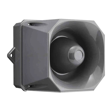
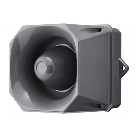
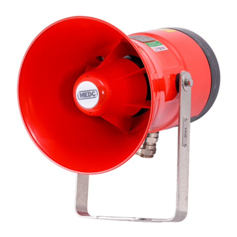
Eaton Crouse-hinds series User manual

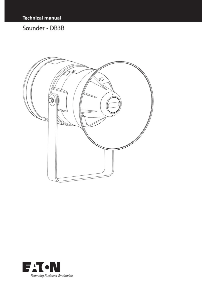
Sounder/Horn – DB3BM UL
Eaton MEDC technical manual
CROUSE-HINDS
SERIES

2SOUNDER/HORN – DB3BM UL TM293 July 2022 www.eaton.com
DISCLAIMER OF WARRANTIES AND LIMITATION OF LIABILITY
The information, recommendations, descriptions and safety notations in this document are based on Eaton Corporation’s
(“Eaton”) experience and judgment and may not cover all contingencies. If further information is required, an Eaton sales
office should be consulted. Sale of the product shown in this literature is subject to the terms and conditions outlined in
appropriate Eaton selling policies or other contractual agreement between Eaton and the purchaser.
THERE ARE NO UNDERSTANDINGS, AGREEMENTS, WARRANTIES, EXPRESSED OR IMPLIED, INCLUDING
WARRANTIES OF FITNESS FOR A PARTICULAR PURPOSE OR MERCHANTABILITY, OTHER THAN THOSE
SPECIFICALLY SET OUT IN ANY EXISTING CONTRACT BETWEEN THE PARTIES. ANY SUCH CONTRACT STATES THE
ENTIRE OBLIGATION OF EATON. THE CONTENTS OF THIS DOCUMENT SHALL NOT BECOME PART OF OR MODIFY
ANY CONTRACT BETWEEN THE PARTIES.
In no event will Eaton be responsible to the purchaser or user in contract, in tort (including negligence), strict liability or
other-wise for any special, indirect, incidental or consequential damage or loss whatsoever, including but not limited to
damage or loss of use of equipment, plant or power system, cost of capital, loss of power, additional expenses in the
use of existing power facilities, or claims against the purchaser or user by its customers resulting from the use of the
information, recommendations and descriptions contained herein. The information contained in this manual is subject to
change without notice.

3SOUNDER/HORN – DB3BM UL TM293.A August 2022 www.eaton.com
Table of content
Contents
INTRODUCTION.........................................................................4
GENERAL SAFETY MESSAGES AND WARNINGS .............................................4
INSTALLATION..........................................................................5
ACCESS TO TERMINALS ..................................................................5
WIRING DETAILS ........................................................................6
OPERATION ............................................................................9
TONE TABLE 1 (STANDARD TONES) .......................................................10
TONE TABLE 2 (VOLT FREE TONE SELECTION) ..............................................11
GENERAL ARRANGEMENT ..............................................................12
MAINTENANCE ........................................................................13
CERTIFICATION / APPROVALS ............................................................14
SPECIAL CONDITIONS FOR SAFE USE.....................................................15

4
TM293 MEDC DB3BM UL Technical Manual
SOUNDER/HORN – DB3BM UL TM293.A August 2022 www.eaton.com
1.0 INTRODUCTION
This range of sounders, intended for use in potentially
explosive gas and dust atmospheres is manufactured
from either stainless steel or marine grade alloy with
a rugged thermoplastic flare.
Stainless steel mounting bracket, cover screws and
fixings are incorporated throughout thus ensuring a
corrosion free product. An ordinary locations version is
available for use in non-explosive atmospheres.
The units are suitable for Indoor and outdoor use and use
in wet environments
2.0 GENERAL SAFETY MESSAGES
AND WARNINGS
All instructions and safety messages in this manual must
be followed to allow safe installation of the device. The
device must only be installed and maintained by correctly
trained site personnel/installers.
• To reduce the risk of ignition of hazardous atmospheres
and shock, do not apply power to the device until
installation has been completed and the device is fully
sealed and secured.
• CAUTION – To reduce the risk of ignition of hazardous
atmospheres: disconnect from supply before opening.
Keep tightly closed when in operation.
• Warning – To reduce the risk of ignition of hazardous
atmospheres conduit openings must have a sealing
fitting connected within 50mm of the enclosure
• If employed for Division 2 applications, the installation
wiring and sealing method required to maintain the
specific type of protection shall be in accordance with
the relevant section of the NEC CEC i.e. For Class I
Division 2 locations the equipment shall either installed
as a Class I Division 1 Explosion proof product or Class
I Zone 1 Flameproof product. For Class II Division 2 or
Class III, the products shall be installed as a Zone 21
product based on protection from dust by enclosure
• Before removing the cover for installation or
maintenance, ensure that the power to the device
is isolated.
• Following installation, test the device to ensure
correct operation.
• Following installation ensure a copy of this manual is
made available to all operating personnel
• When installing the device, requirements for selection,
installation and operation should be referred to e.g. IEE
Wiring Regulations and the ‘National Electrical Code’
ANSI/NFPA70 in North America. Additional national and/
or local requirements may also apply e.g. CSA 22.1.
NFPA72 and ULC-S524
• Cable termination should be in accordance with the
specification applying to the required application.
MEDC recommends that all cables and cores should be
correctly identified. Please refer to the wiring diagram
in this manual (or separate diagram provided with the
unit).
• Ensure that only the correct listed or certified cable
glands are used and that the assembly is shrouded
and correctly earthed. Listed glands suitable for Class
I, Zone 1, Zone 21 with required NEMA ratings should
be used.
• Ensure that only the correct listed or certified stopping
plugs are used to blank off unused gland entry points
in accordance with EN/IEC60079-14 clauses 16.3, 16.4
& 16.5 (for Canadian Zones, refer to C22.1-15) and that
the outdoor wet rating of the unit is maintained.
• The internal grounding terminal shall be used for the
grounding connection and the external terminal, if
available, is for a supplementary bonding connection
where local codes or authorities permit or require such
a connection. The connection to the external earth
terminal shall be made by use of a UL 486E compliant
wire connection.
• When installing the device, MEDC recommends the
use of stainless steel fasteners. Ensure that all nuts,
bolts and fixings are secure.
• The unit should be positioned such that debris, dust or
water cannot settle in the re-entrant horn.
• The unit should be positioned such that any solid
object, not part of the equipment, is a minimum of
40mm from the Ex d flamepath joint.
• The front driver cover of the unit, situated underneath
the thermoplastic main flare, which encloses the
loudspeaker driver shall not be opened as it is not for
field installation or maintenance use
• Caution – Do not paint. Do not alter manufacturer
applied finishes.
• Potential Electrostatic Charging Hazard, protect from
direct airflow from exhaust ducts and the like that
may cause a charge transfer. If the unit requires
cleaning, only clean exterior with a damp cloth to avoid
electrostatic charge build-up. Ensure the equipment is
correctly earthed.

5
TM293 MEDC DB3BM UL Technical Manual
SOUNDER/HORN – DB3BM UL TM293.A August 2022 www.eaton.com
3.0 INSTALLATION
The unit is mounted via 2 off Ø23/64” (Ø9mm) fixing
holes in the U-shaped stirrup/mounting bracket. If
required, the unit can be initially placed via the Ø33/64”
(Ø13mm) central hole in the stirrup. The unit can then
be rotated to the required position and fixed via the
other holes.
If ordered with the unit, a swivel mounting bracket option
is available to allow further rotational adjustment to
the unit.
The fixing holes have been designed to accept a Ø5/16”
(M8) screw or bolt.
Warning – Use a support system which has sufficient
wind load strength to comply with the applicable codes
and standards. To prevent the collection of dust and
foreign objects it is recommended that the horn is
mounted horizontally or pointing downward.
Warning – The drilling of field wiring threaded entries is
not permitted.
Access to Terminals
The cover is secured with 6 off M5 cover screws (4.0mm
A/F hexagon key). Once the cover fixings are unscrewed,
the cover can be lifted away from the enclosure to gain
access to the interior. The cover fixings are captive and
will remain in the cover.
It is intended that the conductors used for supply and
earth connections of the unit shall be 2.5mm² (14AWG).
For supply connections be aware that cable temperature
rise may be up to 30K.
Once termination is complete, carefully replace the
cover assembly back onto the body, avoiding damage to
the mating surfaces. Tighten the cover screws evenly.
Ensure the O-ring is seated correctly on the cover during
re-assembly. Ensure the required maximum gap of
0.025mm is maintained between the cover and the base
once assembled. To maintain the IP rating of the unit, the
recommended torque on the cover screws is 26.5 lbf-in
3.0Nm.
AC input wiring details (Types 1 & 2)
•Type 1: Connect the live and neutral supply wires to the
terminals as detailed in the wiring diagram. The unit will
be supplied with the link between R1 and R0 fitted to
the terminals. When power is applied to the unit, the
stage 1 tone will be produced as selected on the 5- way
DIP switch.
•Type 2: Connect the live and Neutral supply wires to
the terminals as detailed in the wiring diagram. The unit
will be supplied with no link fitted between R1 and R0.
Connect wires and remote switches to terminals R0,
R1 and R2 as shown. When power is initially applied
to the unit, no tone will be produced. When the switch
connected to R1 is closed, the stage 1 tone will be
produced as selected by the 5-way DIP switch on the
electronics assembly. When the switch connected to R2
is closed, the pre-selected tone for stage 2 is produced.
See tone table 2 for details of pre-selected tones.
ote:N Closing both switches will produce no tone.
Wiring details
The unit is available in a number of basic configurations:
Type 1: AC input, single stage.
Type 2: AC input, dual stage with voltage-free stage
selection.
Type 3: DC input, up to 3 user selectable stages
without monitoring.
Type 4: DC input, up to 2 user selectable stages with
EOL / monitoring (standard configuration).
Type 5: DC input, up to 3 user selectable stages
with optional EOL / monitoring (alternative
configuration).
Type 6: DC input, 5 user selectable stages with voltage
free stage selection with or without
monitoring.

6
TM293 MEDC DB3BM UL Technical Manual
SOUNDER/HORN – DB3BM UL TM293.A August 2022 www.eaton.com
DC input, 3 stage without monitoring wiring
details (Type 3)
This type can be configured in a number of different ways
depending on requirements. Independent tone selection
for all 3 stages is via the 3 off 5-way DIP switches fitted to
the electronics assembly:
•2-wire system (Single stage): Connect the positive and
negative supply wires to the terminals as detailed in the
wiring diagram.
•2-wire system (Dual stage, reverse polarity): Connect
the positive and negative supply wires to the terminals
as detailed in the wiring diagram. The second stage is
produced by reversing the polarity of the supply to the
unit.
•3-wire system (Dual stage, common +ve): Connect 3
supply wires to the terminals as detailed in the wiring
diagram (1 common +ve wire and 2 -ve wires). Stage 1
is produced when power is applied across the common
+ve and stage 1 -ve terminals. Stage 2 is produced
when power is applied across the common +ve and
stage 2 -ve terminals.
•3-wire system (Dual stage, common -ve): Connect 3
supply wires to the terminals as detailed in the wiring
diagram (2 +ve wires and 1 common -ve wire). Stage
1 is produced when power is applied across the stage
1 +ve and common -ve terminals. Stage 2 is produced
when power is applied across the stage 2 +ve and
common -ve terminals.
•4-wire system (Triple stage, Common -ve): Connect 4
supply wires to the terminals as detailed in the wiring
diagram (3 +ve wires and 1 common -ve wire). Stage
1 is produced when power is applied across the stage
1 +ve and common -ve terminals. Stage 2 is produced
when power is applied across the stage 2 +ve and
common -ve terminals. Stage 3 is produced when
power is applied across the stage 3 +ve and common
-ve terminals.
All versions are supplied with terminals to allow loop-in
loop-out connection of the supply wires
ote:N If an EOL resistor is specified on a DC unit, it will
be fitted as standard across terminals 5 & 6 in
the Exd chamber (see below). Re-position EOL as
required for other configurations.
When positioning the EOL, ensure there is a
minimum of 9/16” (14mm) free space between the
resistor body and terminal block and ensure the
resistor is not in contact with the PCB or housing.

7
TM293 MEDC DB3BM UL Technical Manual
SOUNDER/HORN – DB3BM UL TM293.A August 2022 www.eaton.com
DC input, dual stage common +ve with monitoring
(standard configuration) wiring details (Type 4)
Connect up to 4 supply wires to the terminals as detailed
in the wiring diagram. Stage 1 is produced when power
is applied across the common +ve and stage 1 -ve
terminals. Stage 2 is produced when power is applied
across the common +ve and stage 2 -ve terminals.
Monitoring functionality is obtained when the supply is
connected across M1 & M2 terminals.
ote:N monitored terminals are not polarity dependent
DC input, up to 3 stage with or without monitoring
(alternative configuration) wiring details (Type 5)
ote:N This alternative configuration must be specified
when ordering the unit.
This type can be connected either as a three stage
common –ve configuration, or if an optional EOL is
specified if can be configured as a dual stage common
–ve system with monitoring.
•4-wire system (Triple stage, Common +ve): Connect 4
supply wires to the terminals as detailed in the wiring
diagram (1 common +ve wire and 3 -ve wires). Stage 1
is produced when power is applied across the common
+ve and stage 1 -ve terminals. Stage 2 is produced
when power is applied across the common +ve and
stage 2 -ve terminals. Stage 3 is produced when power
is applied across the common +ve and stage
3 -ve terminals.
•4-wire system (Dual stage, common –ve with
monitoring): Connect up to 4 supply wires to the
terminals as detailed in the wiring diagram. Stage 1 is
produced when power is applied across the common
-ve and stage 1 +ve terminals. Stage 2 is produced
when power is applied across the common -ve and
stage 2 +ve terminals.
Monitoring functionality is obtained when the supply is
connected across M1 & M2 terminals.
ote:N monitored terminals are not polarity dependent

8
TM293 MEDC DB3BM UL Technical Manual
SOUNDER/HORN – DB3BM UL TM293.A August 2022 www.eaton.com
DC input with voltage free stage activation
wiring details (Type 6)
Connect the positive (+ve) and negative (-ve) supply wires
to the terminals as detailed in the wiring diagram. When
power is applied to the unit, no tone will be produced
initially. Connect wires and remote switches to terminals
R0 to R5 as shown. When the switch connected to R1 is
closed, the stage 1 tone will be produced as selected by
the 5-way DIP switch on the electronics assembly. When
any of the other switches connected to R2 to R5 is closed,
the pre-selected tone for stages 2 to 5 are produced. See
tone table 2 for details of pre-selected tones.
ote:N Closing more than one switch at a time will result in
no tone being produced.
If a resistor (R1) is fitted, monitoring functionality is
obtained when the supply polarity is reversed.

9
TM293 MEDC DB3BM UL Technical Manual
SOUNDER/HORN – DB3BM UL TM293.A August 2022 www.eaton.com
4.0 OPERATION
The sounder is available in various AC input voltage
versions and a single DC input voltage version.
For AC versions, the nominal operating voltage is stated on
the unit label and the supply voltage tolerance is ±10%.
For DC versions, the absolute input voltage range is
11.0Vdc to 57.6Vdc. For full ratings data see section 6
If using EOL resistors the maximum total power
dissipation of the resistors will be limited to 3W.
The unit is fitted with a volume control which is positioned
on the top face of the electronics assembly PCB.
Maximum volume is obtained when this control is turned
fully clockwise. When turned fully anti-clockwise the unit
will emit no sound.
Warning: Do not attempt to turn the volume control past
its limits of movement as this may cause damage to the
unit.
Warning: The unit has a certified upper operating
temperature limit of +85°C, however continuous operation
is not recommended in ambient temperatures above
+70°C
Sound Pressure Output
Minimum Audibility ratings according to UL464 and sound
pressure level according to CAN/ULC-S525 are below as
tested on tones 4,14,19 and 28
Directional Characteristics
Rated SPL directional characteristics as measured in
accordance with CAN/ULC-S525-07 at 11v DC / 2850Hz
at 3 Meters
Flare Option. Tone No. Audibility Rating UL464
(OSPL dBA at 10ft) Can/ULC-S525
(OSPL dbA at 3M)
Long Flare 481.4 97.8
Long Flare 14 93.0 92.9
Long Flare 28 92.6 107.6
Long Flare 19 89.0 98.6
Short Flare 481.5 89.4
Short Flare 14 87.7 92.4
Short Flare 28 91.3 101.6
Short Flare 19 80.9 91.0
Angle OSPL (dBA) Angle OSPL (dBA)
Short Flare Horizontal Axis
On Axis 90° 88.91 On Axis 90° 88.91
120° 85.78 (-3dBA) 55° 85.26 (-3dBA)
130° 82.49 (-6dBA) 50° 82.37 (-6dBA)
180° 63.1 0° 78.24
Short Flare Vertical Axis
On Axis 90° 88.76 On Axis 90° 88.76
130° 84.45 (-3dBA) 55° 86.02 (-3dBA)
135° 82.79 (-6dBA) 50° 81.21 (-6dBA)
180° 56.39 0° 72.8

10
TM293 MEDC DB3BM UL Technical Manual
SOUNDER/HORN – DB3BM UL TM293.A August 2022 www.eaton.com
Angle OSPL (dBA) Angle OSPL (dBA)
Long Flare Horizontal Axis
On Axis 90° 96.31 On Axis 90° 96.31
100° 93.09 (-3dBA) 75° 93.26 (-3dBA)
105° 89.42 (-6dBA) 65° 89.79 (-6dBA)
180° 71.56 0° 79.58
Long Flare Vertical Axis
On Axis 90° 96.33 On Axis 90° 96.33
100° 93.89 (-3dBA) 75° 92.47 (-3dBA)
105° 93.89 (-3dBA) 65° 89.34 (-6dBA)
180° 70.62 0° 75.23
Stages:
For all versions, a 5-way DIP switch selects the stage
required for each stage. The settings for the standard
stages are shown in the table below:
TONE No. TONE FREQUENCY/DESCRIPTION SWITCH SETTING 12345 TONE DESCRIPTION Nominal SPL (dB(A) @ 1M)
1Alt Stages 800/970 Hz at 1/4 sec 11111 112
2Sweeping 800/970 Hz at 7 Hz 11110 Fast Sweep (LF) 111
3Sweeping 800/970 Hz at 1 Hz 11101 Medium Sweep (LF) 113
4Continuous at 2850 Hz 11100 111
5Sweeping 2400-2850 Hz at 7 Hz 11011 Fast Sweep 112
6Sweeping 2400-2850 Hz at 1 Hz 11010 113
7Slow Whoop 11001 Slow Whoop 113
8Sweep 1200-500 Hz at 1 Hz 11000 Din Stage 117
9Alt Stages 2400/2850 Hz at 2 Hz 10111 111
10 Int Stage of 970 Hz at 1 Hz 10110 Back-up Alarm (LF) 112
11 Alt Stages 800/970 Hz at 7/8 Hz 10101 112
12 Int Stage at 2850 Hz at 1Hz 10100 Back-up Alarm (HF) 112
13 970 Hz at 1/4 sec on 1 sec off 10011 112
14 Continuous at 970 Hz 10010 112
15 554 Hz for 0.1S/440 Hz for 0.4S 10001 French Fire Sound 113
16 Int 660 Hz 150 mS on 150 mS off 10000 Swedish Fire Alarm 108
17 Int 660 Hz 1.8 sec on 1.8 sec off 01111 Swedish Fire Alarm 108
18 Int 660 Hz 6.5 sec on 13 sec off 01110 Swedish Fire Alarm 109
19 Continuous 660 Hz 01101 Swedish Fire Alarm 108
20 Alt 554/440 Hz at 1 Hz 01100 Swedish Fire Alarm 113
21 Int 660 Hz at 7/8 Hz 01011 Swedish Fire Alarm 108
Tone table 1:

11
TM293 MEDC DB3BM UL Technical Manual
SOUNDER/HORN – DB3BM UL TM293.A August 2022 www.eaton.com
TONE No. TONE FREQUENCY/DESCRIPTION SWITCH SETTING 12345 Voltage free stage selection tone No.
DC AC
Stage 1 Stage 2 Stage 3 Stage 4 Stage 5 Stage2
1Alt Tones 800/970Hz at 1/4 sec 11111 T14 T10 T11 T8 T14
2Sweeping 800/970Hz at 7 Hz 11110 T14 T10 T1 T8 T14
3Sweeping 800/970Hz at 1 Hz 11101 T14 T10 T1 T8 T14
4Continuous at 2850Hz 11100 T14 T10 T1 T8 T14
5Sweeping 2400-2850Hz at 7Hz 11011 T14 T10 T1 T8 T14
6Sweeping 2400-2850Hz at 1Hz 11010 T14 T10 T1 T8 T14
7Slow Whoop 11001 T14 T10 T1 T8 T14
8Sweep 1200-500Hz at 1Hz 11000 T14 T10 T1 T6 T14
9Alt Tones 2400/2850Hz at 2Hz 10111 T14 T10 T1 T8 T14
10 Int Tone of 970Hz at 1Hz 10110 T14 T12 T1 T8 T14
11 Alt Tones 800/970Hz at 7/8Hz 10101 T14 T10 T1 T8 T14
12 Int Tone at 2850Hz at 1Hz 10100 T14 T10 T1 T8 T14
13 970Hz at 1/4 sec on 1 sec off 10011 T14 T10 T1 T8 T14
14 Continuous at 970Hz 10010 T28 T10 T1 T8 T28
15 554Hz for 0.1S/440Hz for 0.4S 10001 T14 T10 T1 T8 T14
16 Int 660Hz 150 mS on 150 mS off 10000 T14 T10 T1 T8 T14
17 Int 660Hz 1.8 sec on 1.8 sec off 01111 T14 T10 T1 T8 T14
18 Int 660Hz 6.5 sec on 13 sec off 01110 T14 T10 T1 T8 T14
19 Continuous 660Hz 01101 T14 T10 T1 T8 T14
20 Alt 554/440Hz at 1Hz 01100 T14 T10 T1 T8 T14
21 Int 660Hz at 7/8Hz 01011 T14 T10 T1 T8 T14
22 Int 2850Hz 150 mS on 100 mS off 01010 T14 T10 T1 T8 T14
23 Sweep 800-970Hz at 50Hz 01001 T14 T10 T1 T8 T14
24 Sweep 2400-2850Hz at 50Hz 01000 T14 T10 T1 T8 T14
25 3x970Hz pulses 0.5 off, 1.5 off 00111 T14 T10 T1 T8 T14
26 3x2850Hz pulses 0.5on/0.5off, 1.5 off 00110 T14 T10 T1 T8 T14
27 Int 3100Hz 0.32s on/0.68s off 00101 T14 T10 T1 T8 T14
28 Continuous 1400Hz 00100 T14 T10 T1 T8 T14
29 Spare / Custom tone 00011
30 Spare / Custom tone 00010
31 Spare / Custom tone 00001
32 Spare / Custom tone 00000
Tone table 2: Pre-selected tone details for voltage-free activation stages:
TONE No. TONE FREQUENCY/DESCRIPTION SWITCH SETTING 12345 TONE DESCRIPTION Nominal SPL (dB(A) @ 1M)
22 Int 2850 Hz 150 mS on 100 mS off 01010 Pelican Crossing 111
23 Sweep 800-970 Hz at 50 Hz 01001 Low Freq. Buzz 109
24 Sweep 2400 -2850 Hz at 50 Hz 01000 High Freq. Buzz 111
25 3x970 Hz pulses 0.5 off, 1.5 off 00111 112
26 3x2850 Hz pulses 0.5on/0.5off, 1.5 off 00110 112
27 Int 3100 Hz 0.32s on/0.68s off 00101 105
28 Continuous 1400 Hz 00100 125
29 Spare / Custom tone 00011
30 Spare / Custom tone 00010
31 Spare / Custom tone 00001
32 Spare / Custom tone 00000
ote:N If special tones were requested at the time of ordering, please see the separate
tones list supplied with the unit for details of these special tones and their
respective switch settings.

12
TM293 MEDC DB3BM UL Technical Manual
SOUNDER/HORN – DB3BM UL TM293.A August 2022 www.eaton.com
GENERAL ARRANGEMENT

13
TM293 MEDC DB3BM UL Technical Manual
SOUNDER/HORN – DB3BM UL TM293.A August 2022 www.eaton.com
5.0 MAINTENANCE
During the working life of the unit, it should require
little maintenance however; if abnormal or unusual
environmental conditions occur due to plant damage or
accident etc., then visual inspection is recommended.
WARNING! – The front driver cover of the unit, situated
underneath the thermoplastic main flare, which encloses
the loudspeaker driver shall not be opened as it is not for
field installation or maintenance use.
See below diagram for details of the flameproof joints
found in the unit. WARNING! – The flameproof joints
details below are not intended to be repaired.
Corrosion inhibiting grease, such as petrolatum or soap-
thickened mineral oils, may be applied to flameproof joint
surfaces before assembly. The grease, if applied, shall be
of a type that does not harden because of ageing, does
not contain an evaporating solvent, and does not cause
corrosion of the joint surfaces. Verification of suitability
shall be in accordance with the grease manufacturer’s
specifications.
Aluminium Alloy cover joints must be cleaned before
replacing cover
If the unit requires cleaning, the only clean exterior with
a damp cloth to avoid electro-static charge build up.
If a unit fault should occur, then the unit can be repaired
by MEDC
If you acquired a significant quantity of units, then it is
recommended that spares are also made available. It
should be noted that if damaged the external thermoplastic
horn may be replaced as a complete part or the snap in end
cap may be replaced separately. Please discuss your spares
requirements with the Technical Sales Engineers at Eaton
MEDC.
Snap in end cap
can be replaced
as a spare part,
see below

14
TM293 MEDC DB3BM UL Technical Manual
SOUNDER/HORN – DB3BM UL TM293.A August 2022 www.eaton.com
6.0 CERTIFICATION / APPROVALS
UL listed for use in USA (USL) and Canada (CNL)
Please refer to the marking on the unit for specific
approval details
(USL) Zone 1, AEx db IIC Gb T*
Zone 21, AEx tb IIIC Db T*
Class I, Division 1, Groups A, B, C & D
(CNL) Ex db IIC Gb T*
Ex tb IIIC Db T*
Class I, Division 1, Groups B, C & D
Also suitable for: Class I, Division 2, Groups A, B, C & D
Class II
Division 2 Groups F&G
Class III Division 2
Applicable Standards:
(USL) UL60079-0, Edition 7
UL60079-1, Edition 7
UL60079-31, Edition 2
UL1203, Edition 5
(CNL) CSA C22.2 No. 60079-0 :Edition 4
CSA C22.2 No. 60079-1:16
CSA C22.2 No. 60079-31:15
CSA C22.2 No. 30-M1986,
Edition 3 R2016
*T-Ratings:
Max. Power
rating Tamb. TGTD
15W -60°C to +85°C T4 T135°C
-60°C to +55°C T5 T100°C
-60°C to +40°C T6 T85°C
Electrical Ratings
1. 12 V to 48 Vdc, 716 mA to 171 mA, Special Application†
2. 24V Vdc regulated 356mA
3. 110 Vac, 50/60 Hz, 122mA, Special Applicaton.
4. 120 Vac, 50/60 Hz, 110mA, Regulated.
5. 220/230/ Vac, 50/60 Hz, 63 mA, Special Application.
6. 240 Vac, 50/60 Hz, 58 mA, Regulated
ote:N † the DC special application version is suitable for
use with 24Vdc regulated supplies.

15
TM293 MEDC DB3BM UL Technical Manual
SOUNDER/HORN – DB3BM UL TM293.A August 2022 www.eaton.com
7.0 SPECIAL CONDITIONS FOR SAFE USE
• For replacement purposes M5 x 0.8 x 20 mm long
cover bolts shall be used and shall have a property
class of A2-70 or stronger. Reduced shank fasteners
must be used with covers employing threaded holes.
Fully threaded fasteners must be used with covers
employing plain clearance holes.
• The flameproof joints are not intended to be repaired.
• Potential Electrostatic Charging Hazard. If the unit
requires cleaning, only clean exterior with a damp cloth
to avoid electrostatic charge build-up. See instructions
for further guidance
• If metal certification labels are attached to the horn
they are known to be capable of retaining the
following charges.
3.33pF - Label size 65mm x 40mm (2.5”x1.5”)
7.15pF Label size 105mm x 42.5mm (4” x 1.3/4”)

16
TM293 MEDC DB3BM UL Technical Manual
SOUNDER/HORN – DB3BM UL TM293.A August 2022 www.eaton.com
EXCLUSION DE GARANTIE ET LIMITATION DE LA RESPONSABILITE
Les informations, des recommandations, des descriptions et des notations de sécurité dans ce document sont basés
sur Eaton Corporation de ( “Eaton”) expérience et le jugement et peuvent ne pas couvrir toutes les éventualités. Si des
informations supplémentaires sont nécessaires, un bureau de vente Eaton devrait être consulté.
La vente du produit indiqué dans cette littérature est soumise aux termes et conditions appropriées décrites dans Eaton
à vendre des polices ou accord contractuel other Entre Eaton et l’acheteur.
IL N’Y A PAS ENTENTES, ACCORDS, GARANTIE, EXPLICITE OU IMPLICITE, Y COMPRIS LES GARANTIES
D’ADAPTATION À UN USAGE PARTICULIER OU DE COMMERCIALISATION, AUTRES QUE CEUX SPECIFIES DANS
TOUT CONTRAT EXISTANT ENTRE LES PARTIES. UN TEL CONTRAT ETATS L’OBLIGATION ENTIER DE EATON. LE
CONTENU DE CE DOCUMENT NE DOIT PAS DEVENIR PARTIE OU MODIFIER TOUT CONTRAT ENTRE LES PARTIES.
En aucun cas, Eaton responsable à l’acheteur ou de l’utilisateur dans le contrat, en responsabilité délictuelle (y compris
la négligence), la responsabilité stricte ou autre sage pour tout dommage spécial, indirect ou consécutif ou toute perte,
y compris mais sans s’y limiter les dommages ou pertes d’utilisation de l’équipement, installation ou du système
d’alimentation, le coût du capital, perte de puissance, les dépenses supplémentaires dans l’utilisation des installations
électriques existantes, ou des réclamations contre l’acheteur ou de l’utilisateur par ses clients résultant de l’utilisation
des informations, des recommandations et des descriptions contenues dans les présentes. Les informations contenues
dans ce manuel sont sujettes à modification sans préavis.

17
TM293 MEDC DB3BM UL Technical Manual
SOUNDER/HORN – DB3BM UL TM293.A August 2022 www.eaton.com
Sommaire
INTRODUCTION........................................................................18
MESSAGES DE SÉCURITÉ ET AVERTISSEMENTS D’ORDRE GÉNÉRAL . . . . . . . . . . . . . . . . . . . . . . . . . .18
INSTALLATION.........................................................................19
ACCÈS AUX BORNES ...................................................................19
DÉTAILS DU CÂBLAGE ..................................................................19
FONCTIONNEMENT ....................................................................23
TABLEAU DES SONS 1 (SONS STANDARD).................................................24
TABLEAU DES SONS 2 (SÉLECTION DES SONS HORS TENSION) . . . . . . . . . . . . . . . . . . . . . . . . . . . . . .26
DISPOSITION GÉNÉRALE ................................................................27
MAINTENANCE ........................................................................28
CERTIFICATION / APPROBATIONS.........................................................29
CONDITIONS PARTICULIÈRES POUR UNE
UTILISATION EN TOUTE SÉCURITÉ........................................................30

18
TM293 MEDC DB3BM UL Technical Manual
SOUNDER/HORN – DB3BM UL TM293.A August 2022 www.eaton.com
1.0 INTRODUCTION
Cette gamme de sirènes, conçue pour une utilisation
dans des atmosphères poussiéreuses et à gaz
potentiellement explosifs, est en acier inoxydable ou en
alliage pour application marine et comprend un cône en
thermoplastique robuste.
L’équerre de montage en acier inoxydable, les vis de
protection et les fixations sont complètement intégrées,
ce qui garantit un produit dépourvu de corrosion. Une
version pour emplacements ordinaires est disponible pour
une utilisation dans des atmosphères non explosives.
Les appareils sont adaptés à une utilisation en intérieur et
en extérieur et dans des environnements humides.
2.0 MESSAGES DE SÉCURITÉ ET AVERTISSEMENTS D’ORDRE GÉNÉRAL
Respectez toutes les instructions et tous les messages
de sécurité de ce manuel pour garantir une installation en
toute sécurité de l’appareil. L’appareil ne doit être installé
et entretenu que par du personnel / des installateurs du
site correctement formés.
• Pour réduire le risque d’inflammation d’atmosphères
dangereuses et le risque d’électrocution, ne branchez
pas l’appareil sur l’alimentation tant que son installation
n’est pas terminée et qu’il n’est pas complètement
étanche et sécurisé.
• ATTENTION – Pour réduire le risque d’inflammation
d’atmosphères dangereuses : débranchez l’alimentation
avant d’ouvrir l’appareil. Conservez l’appareil fermé
hermétiquement pendant son fonctionnement.
• Avertissement – Pour réduire le risque d’inflammation
d’atmosphères dangereuses, les ouvertures de conduit
doivent être dotées d’un raccord d’étanchéité connecté
à moins de 50 mm du boîtier.
• Si l’appareil est employé pour des applications de
Division 2, le câblage d’installation et la méthode
d’étanchéité requis pour maintenir le type de protection
spécifique doivent être conformes à la section
correspondante du NEC CEC ; autrement dit, pour les
sites de Classe I, Division 2, l’équipement doit être
installé en tant que produit antidéflagrant de Classe
I, Division 1 ou de Classe I, Zone 1. Pour la Classe II,
Division 2 ou la Classe III, les produits doivent être
installés en tant que produits de Zone 21 en fonction
de la protection contre la poussière fournie par le
boîtier.
• Avant de retirer le couvercle pour l’installation ou
la maintenance, assurez-vous que l’alimentation de
l’appareil est isolée.
• Une fois l’appareil installé, testez le bon
fonctionnement de ce dernier.
• Une fois l’installation terminée, assurez-vous qu’un
exemplaire de ce manuel est mis à la disposition de
tout le personnel d’exploitation.
• Lors de l’installation de l’appareil, les normes de
sélection, d’installation et d’utilisation de l’appareil
doivent être mentionnées ; par exemple, les
réglementations de câblage IEE et le « Code national
de l’électricité » ANSI/NFPA70 en Amérique du Nord.
Des normes nationales et/ou locales supplémentaires
peuvent également s’appliquer, par exemple, CSA 22.1.
NFPA72 et ULC-S524
• Le raccordement des câbles doit être conforme aux
spécifications applicables à l’application requise. MEDC
recommande d’identifier correctement tous les câbles
et conducteurs. Reportez-vous au schéma de câblage
de ce manuel (ou au schéma fourni avec l’appareil).
• Assurez-vous que seuls les presse-étoupes
correctement répertoriés ou certifiés sont utilisés
et que l’ensemble est protégé et correctement mis
à la terre. Utilisez les presse-étoupes répertoriés
adaptés à la Classe I, Zone 1 et Zone 21 possédant les
caractéristiques nominales NEMA requises.
• Assurez-vous que seuls les bouchons correctement
répertoriés ou certifiés sont utilisés pour obturer
les points d’entrée de presse-étoupes non utilisés
conformément aux clauses EN/IEC60079-14 16.3, 16.4
et 16.5 (pour les zones au Canada, reportez-vous à la
norme C22.1-15) et que l’indice d’humidité extérieur de
l’appareil est maintenu.
• La borne de mise à la terre interne doit être utilisée
pour la connexion de mise à la terre et la borne
externe, le cas échéant, est destinée à une connexion
de liaison supplémentaire lorsque les réglementations
locales ou les autorités locales autorisent ou exigent
une telle connexion. La connexion à la borne de terre
externe doit être effectuée à l’aide d’une connexion
filaire conforme à la norme UL 486E.
• Dans le cadre de l’installation de l’appareil, MEDC
recommande d’utiliser des fixations en acier
inoxydable. Assurez-vous que l’ensemble des écrous,
boulons et fixations est bien serré.
• Positionnez l’appareil de manière à ce que les débris, la
poussière ou l’eau ne puissent pas se déposer dans le
pavillon rentrant.
• Positionnez l’appareil de manière à ce que tout objet
solide ne faisant pas partie de l’équipement se trouve à
au moins 40 mm du joint de chemin de flamme Ex d.
• N’ouvrez pas le couvercle avant de l’appareil situé sous
le cône principal en thermoplastique, qui renferme le
moteur du haut-parleur, car il ne s’installe pas sur site
et ne fait pas l’objet d’un entretien.
• Attention – N’appliquez pas de peinture sur l’appareil.
N’altérez pas les finitions appliquées par le fabricant.
• Risque de charge électrostatique : protégez des débits
d’air directs provenant des conduits d’échappement et
autres, qui peuvent provoquer un transfert de charge.
Si l’appareil doit être nettoyé, nettoyez l’extérieur avec
un chiffon humide pour éviter l’accumulation de charge
électrostatique. Assurez-vous que l’équipement est
correctement mis à la terre.

19
TM293 MEDC DB3BM UL Technical Manual
SOUNDER/HORN – DB3BM UL TM293.A August 2022 www.eaton.com
3.0 INSTALLATION
Deux trous de fixation excentrés de Ø 9 mm situés dans
l’étrier en U / l’équerre de montage permettent de monter
l’appareil. Si nécessaire, commencez par monter l’appareil
par le trou central de Ø 13 mm de l’étrier. Vous pourrez
alors tourner l’appareil dans la position requise et le fixer
par les autres trous.
Une équerre de montage pivotante, à commander en
même temps que l’appareil, est proposée en option pour
permettre un réglage en rotation supplémentaire de
ce dernier.
Les trous de fixation ont été conçus pour accueillir une vis
ou un boulon de Ø 5/16 ou M8.
Avertissement : utilisez un système de support dont la
résistance à la charge due au vent est suffisante pour
garantir la conformité aux codes et normes applicables.
Pour éviter l’accumulation de poussière et de corps
étrangers, il est recommandé de monter le pavillon à
l’horizontale ou de le diriger vers le bas.
Avertissement : il est interdit de percer des entrées
filetées du câblage de terrain.
Accès aux bornes
Le couvercle est fixé par le biais de 6 vis M5 (clé
hexagonale A/F de 4,0 mm). Une fois les fixations du
couvercle dévissées, retirez le couvercle du boîtier pour
accéder à l’intérieur. Les fixations du couvercle sont
imperdables et resteront dans le couvercle.
Il est prévu que les conducteurs utilisés pour les
raccords d’alimentation et de mise à la terre de l’appareil
soient de 2,5 mm² (14 AWG). Concernant les raccords
d’alimentation, notez que la température des câbles peut
atteindre jusqu’à 30K.
Une fois le raccordement terminé, replacez
soigneusement le couvercle sur le corps, en évitant
d’endommager les surfaces de contact. Serrez les vis
du couvercle uniformément. Assurez-vous que le joint
torique est correctement positionné sur le couvercle
lors du remontage. Veillez à maintenir l’espace maximal
requis de 0,025 mm entre le couvercle et la base une fois
l’appareil assemblé. Pour maintenir l’indice de protection
IP de l’appareil, il est recommandé de serrer les vis du
couvercle au couple de 3,0 Nm.
Détails du câblage
L’appareil est disponible dans un certain nombre de
configurations de base :
Type 1: Entrée CA, une seule phase.
Type 2: Entrée CA, deux phases avec sélection de la
phase hors tension.
Type 3: Entrée CC, jusqu’à 3 phases sélectionnables
par l’utilisateur sans contrôle.
Type 4: Entrée CC, jusqu’à 2 phases sélectionnables
par l’utilisateur avec résistance de fin de ligne/
contrôle (configuration standard).
Type 5: Entrée CC, jusqu’à 3 phases sélectionnables
par l’utilisateur avec résistance de fin de ligne
/contrôle en option (configuration alternative).
Type 6: Entrée CC, 5 phases sélectionnables par
l’utilisateur avec sélection de la phase hors
tension avec ou sans contrôle.
Détails du câblage d’entrée CA (types 1 et 2)
• Type 1: Connectez les fils d’alimentation sous tension
et neutre aux bornes, comme indiqué dans le schéma
de câblage. L’appareil est fourni avec la liaison entre
R1 et R0 montée sur les bornes. Lorsque l’appareil est
sous tension, le son de la phase 1 est émis, selon la
sélection effectuée sur le commutateur DIP 5 voies.
• Type 2: Connectez les fils d’alimentation sous tension
et neutre aux bornes, comme indiqué dans le schéma
de câblage. L’appareil est fourni sans liaison entre R1
et R0. Connectez les fils et les interrupteurs distants
aux bornes R0, R1 et R2, comme illustré. Lors de
la première mise sous tension de l’appareil, aucun
son n’est émis. Lorsque l’interrupteur connecté à R1
est fermé, le son de la phase 1 est émis, selon la
sélection effectuée sur le commutateur DIP 5 voies
sur l’ensemble électronique. Lorsque l’interrupteur
connecté à R2 est fermé, le son présélectionné pour la
phase 2 est émis. Reportez-vous au tableau des sons 2
pour en savoir plus sur les sons présélectionnés.
Remarque : si les deux interrupteurs sont fermés,
aucun son n’est émis.

20
TM293 MEDC DB3BM UL Technical Manual
SOUNDER/HORN – DB3BM UL TM293.A August 2022 www.eaton.com
Détails du câblage d’entrée CC, 3 phases sans
contrôle (type 3)
Ce type peut être configuré de différentes manières en
fonction des besoins. La sélection du son est effectuée
de façon indépendante pour les 3 phases à l’aide des
3 commutateurs DIP 5 voies montés sur l’ensemble
électronique :
• Système à 2 fils (une seule phase) : Connectez les
fils d’alimentation positif et négatif aux bornes, comme
indiqué sur le schéma de câblage.
• Système à 2 fils (deux phases, polarité inversée) :
Connectez les fils d’alimentation positif et négatif aux
bornes, comme indiqué sur le schéma de câblage. La
deuxième phase est produite en inversant la polarité de
l’alimentation de l’appareil.
• Système à 3 fils (deux phases, commun positif) :
Connectez 3 fils d’alimentation aux bornes, comme
indiqué sur le schéma de câblage (1 fil commun positif
et 2 fils négatifs). La phase 1 est produite lorsque
l’alimentation est appliquée sur la borne commune
positive et sur la borne négative de la phase 1. La
phase 2 est produite lorsque l’alimentation est
appliquée sur la borne commune positive et sur la
borne négative de la phase 2.
• Système à 3 fils (deux phases, fil commun négatif)
:Connectez 3 fils d’alimentation aux bornes, comme
indiqué sur le schéma de câblage (2 fils positifs et 1
fil commun négatif). La phase 1 est produite lorsque
l’alimentation est appliquée sur la borne positive de la
phase 1 et sur la borne commune négative. La phase 2
est produite lorsque l’alimentation est appliquée sur la
borne positive de la phase 2 et sur la borne commune
négative.
• Système à 4 fils (trois phases, fil commun négatif)
:Connectez 4 fils d’alimentation aux bornes, comme
indiqué sur le schéma de câblage (3 fils positifs et 1
fil commun négatif). La phase 1 est produite lorsque
l’alimentation est appliquée sur la borne positive de la
phase 1 et sur la borne commune négative. La phase 2
est produite lorsque l’alimentation est appliquée sur la
borne positive de la phase 2 et sur la borne commune
négative. La phase 3 est produite lorsque l’alimentation
est appliquée sur la borne positive de la phase 3 et sur
la borne commune négative.
Toutes les versions sont fournies avec des bornes pour
permettre les connexions en boucle d’entrée et de sortie
des fils d’alimentation
Remarque : si une résistance de fin de ligne est
commandée sur un appareil CC, elle est
montée en série sur les bornes 5 et 6 de la
cavité Exd (cf. ci-dessous). Repositionnez la
résistance de fin de ligne selon les besoins
pour les autres configurations.
Lors du positionnement de la résistance de
fin de ligne, assurez-vous qu’il y a un espace
libre d’au moins 14 mm entre le corps
de la résistance et le bornier, puis que la
résistance n’est pas en contact avec la carte
de circuit imprimé ou le boîtier.
Other manuals for Crouse-hinds series
95
This manual suits for next models
1
Table of contents
Languages:
Other Eaton Marine Equipment manuals

Eaton
Eaton DB3P User manual

Eaton
Eaton MEDC EV21 User manual

Eaton
Eaton SDR-RINT User manual

Eaton
Eaton X 10 DC User manual

Eaton
Eaton Crouse-hinds series User manual

Eaton
Eaton ULCAS380 User manual

Eaton
Eaton MEDC EV24 User manual

Eaton
Eaton X10 User manual

Eaton
Eaton EV11 User manual

Eaton
Eaton SQG3 Series Instruction manual