Abus Eyseo TV7220 User manual

Progressive Scan CCD network camera
Installation instructions
Version 1.2
TV7220 - TV7223

2
Preface
Dear Customer,
Thank you for purchasing this network camera of the Eyseo series from ABUS Security-Center. You made
the right decision in choosing this state-of-the-art technology,
which complies with the current standards of domestic and European regulations. The CE has been proven
and all related certifications are available from the manufacturer upon request.
To maintain this status and to guarantee safe operation, it is your obligation to observe these operating
instructions! In the event of questions, please contact your local specialist dealer.
This network camera is used for object surveillance. The recorded video signals are transmitted to a
computer digitally via the connected network. The computer software permits simultaneous recording of up
to 16 connected video signals. Data storage is subject to local national data-protection guidelines. Via the
Internet Explorer, you have worldwide access to installed cameras (password-protected).
Precautions
The network camera and connected components must be kept free of moisture (cellars and similar
surroundings are to be strictly avoided). Use of this product for other than the described purpose may lead to
damage of the product. Other hazards such as short-circuiting, fire, electric shock, etc., are also possible.
The equipment is designed for operation using a Class 2 12V DC transformer. No part of the product may be
changed or modified in any way. Connection to the public power network is subject to country-specific
regulations. Please be aware of applicable regulations in advance.
To avoid fire and injury, please observe the
following:
Securely fasten the device at a dry location in
the building.
Ensure sufficient air circulation.
Do not expose the device to temperatures less
than 0°C or more than 35°C.
The device is designed for indoor use only.
Humidity must not exceed 90% (non-
condensed).
Ensure that the voltage is disconnected when
performing work on the device.
Please observe the following regulations to
ensure trouble-free operation of your
device.
The network camera is supplied by a 12V DC
transformer.
The transformer should be connected to the
230V AC building mains by means of a
separate, electrically protected line.
Connection work to the building mains is
subject to country-specific regulations
General:
Improper or careless installation work may lead to faults and poor image quality. Therefore please read the
instructions very carefully and follow the installation instructions for lines and components precisely.
The manufacturer reserves the right to make technical modifications at any time.

3
Before using this product
The use of surveillance equipment may be forbidden by law in some countries. This network camera is
not only high-quality web camera but can also be used as part of a flexible surveillance system. Before
using this equipment, make sure that all your surveillance activities are completely legal.
Before installation, check the product for completeness (page 5: Scope of delivery). Read the
installation instructions before installing the network camera. Read the “Hardware installation” chapter
carefully and follow the instructions contained in it to avoid damage caused by faulty assembly or
incorrect installation. This will ensure that the equipment goes into operation correctly for the intended
purpose.
Appendixes A and B contain possible solutions to problems occurring during installation and
configuration.
The installation instructions describe different usage scenarios of the network camera.
Sections marked with contain special hints and advice for the user. Ignoring this advice can
result in damage to the equipment or injury.

4
Contents
Preface .....................................................................................................................................................2
Precautions...............................................................................................................................................2
Before using this product..........................................................................................................................3
Contents ...................................................................................................................................................4
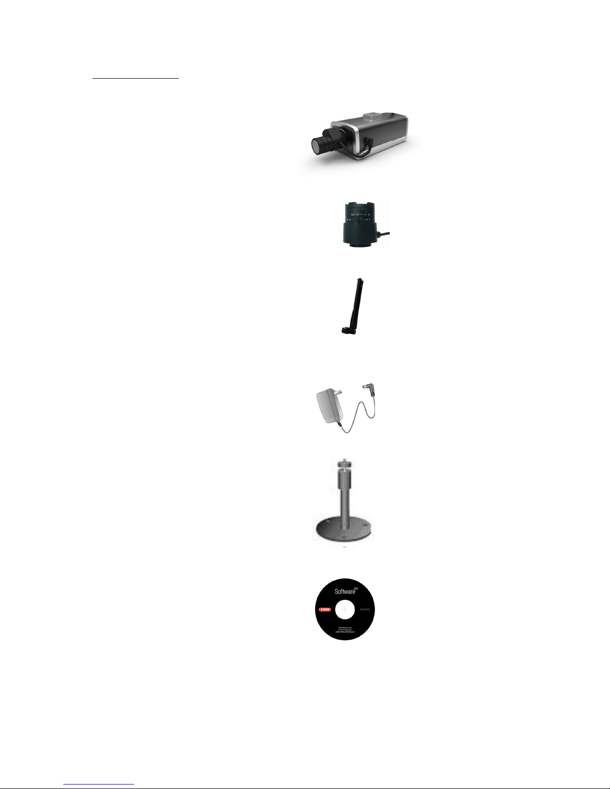
Scope of delivery ......................................................................................................................................5
Hardware installation ................................................................................................................................6
Consult your dealer for the correct installation of peripheral devices.......................................................6
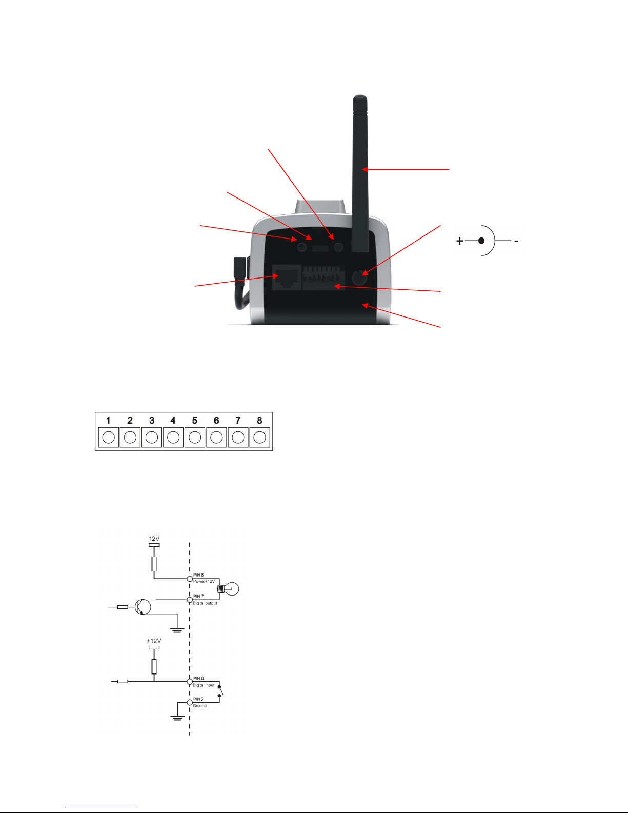
External connections .................................................................................................................. 7
Connections at the rear side ............................................................................................ 7
I/O-connector.................................................................................................................... 7
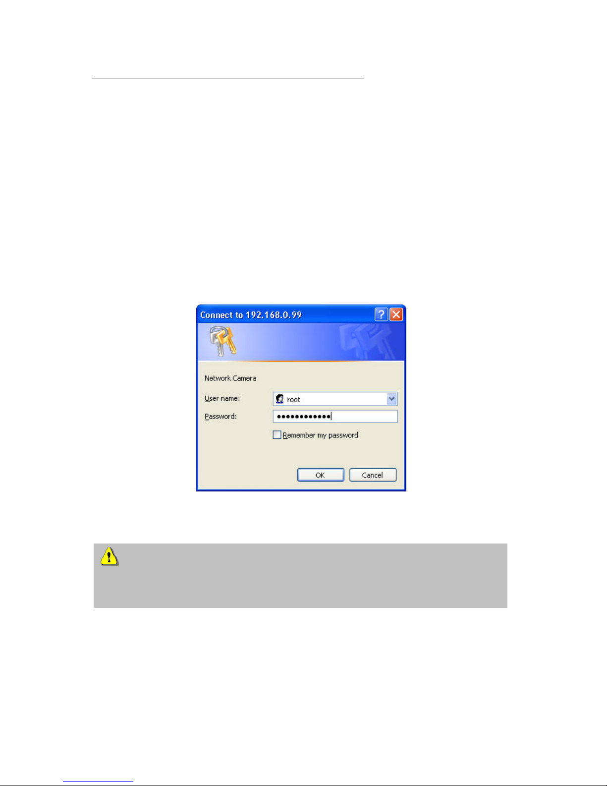
First access to network camera................................................................................................................8
Access to the network camera via the Internet Explorer..........................................................................9
Defining a password to prevent unauthorised access..............................................................................9
Changing the administrator password ...................................................................................... 10
Installing the plug-in.................................................................................................................. 11
Basic user functions ...............................................................................................................................12
Main window and camera view................................................................................................. 12
Digital Zoom and Snapshot ...................................................................................................... 13
Client Settings........................................................................................................................... 14
Administrator settings .............................................................................................................................16
Configuration / video and audio................................................................................................ 16
Protecting the network camera with a password...................................................................... 17
Setting up a surveillance application ........................................................................................ 18
Updating the software version .................................................................................................. 18
System configuration ..............................................................................................................................19
System...................................................................................................................................... 20
Security..................................................................................................................................... 20
Network..................................................................................................................................... 21
WLAN configuration.................................................................................................................. 24
Enable the DDNS function........................................................................................................ 26
Access list................................................................................................................................. 27
Video and audio........................................................................................................................ 28
Privacy Mask .................................................................................................................................. 29
Motion sensor ........................................................................................................................... 31
Application ................................................................................................................................ 32
Media.............................................................................................................................................. 32
Server............................................................................................................................................. 33
Event .............................................................................................................................................. 34
Viewing parameters .................................................................................................................. 36
Maintenance ............................................................................................................................. 36
Appendix.................................................................................................................................................37
A. Troubleshooting.................................................................................................................... 37
B. Frequently asked questions (FAQ) ...................................................................................... 38
C. URL-Commands .................................................................................................................. 40
D. Technical data...................................................................................................................... 73
E. Licence information .............................................................................................................. 74

5
Scope of delivery
Network camera
TV7220/TV7221/TV7222/TV7223
Lens
Antenna (only TV7221/23)
Transformer
Camera stand
Software CD
Installation instructions (on CD)

6
Hardware installation
Installation in Ethernet
The Progressive Scan Network camera tries to connect first to the wired Ethernet. If no Ethernet is
available, then it will try to detect the wireless network using the set value.
After power up the camera, the LED at the front will flash red once, then the start-up procedure will
begin. During assignment of the IP address this LED will turn green continuously. After this procedure
was performed successfully, the LED will flash 1/second in green mode.
Installation in the WLAN
If the camera is supplied with electricity and no Ethernet is available, the camera switches to WLAN
mode and searches for an access point with the name “default”. This name is known as the SSID
(Service Set Identifier). If an access point with the SSID “default” is found, the LED on the front lights
blue.
If connection with the basic settings (SSID: default) is not successful, connect the camera via a cable
to the wired network and configure it.
Make sure that all accessories and articles
listed above are present in the scope of
delivery. Depending on application, an Ethernet
cable may be required. This Ethernet cable
must meet the specifications of UTP Category
5 (CAT 5) and must not be longer than 100
meters.
To prevent the risk of electric shock, first connect the socket of the transformer to the network
camera before inserting the transformer into the mains socket.
Consult your dealer for the correct installation of peripheral devices.

7
External connections
Connections at the rear side
I/O-connector
Switching input and output
12VDC
I/O-Port
Ethernet
connector
Reset
button
1 : not used
2 : not used
3 : not used
4 : not used
5 : Ground
6 : Digital input
7 : Digital output
8 : Power 12VDC
Audio input
Antenna
Audio output
Switch: internal /
external
Microphone

8
First access to network camera
The first access to the network camera should be done by using the Installation Wizard 2.
After the startup of this tool the wizard will search for any connected Eyseo network camera or
videoserver.
The Standard IP address of the videoserver is 169.254.0.99.
If there is a DHCP server running on the network then the IP address assignment will be done
automatically, regarding your network stucture.
The network adapter parameters of thenetwork camera like IP address or subnet mask you can
directly change under [Home / Configuration / Network], and so you can adapt the videoserver
to your network (e.g. IP=192.168.0.99 / subnet mask = 255.255.255.0).
To connect to the network camera just double click the list entry on the result list.
After the start of the Installation wizard 2 the tool might add a virtual IP address to the current
network settings of the PC. It depends whether DHCP in your network is activated or not.
After shut down of the Installation wizard 2 this virtual IP address will be removed.
Using this virtual IP address the first access and configuration process will be much easier. A
manual configuration of the network adapter of the PC is therefore not necessary.

9
Access to the network camera via the Internet Explorer
Defining a password to prevent unauthorised access
When delivered, no administrator password is defined for the network camera.
The network camera asks for this number at the start of operation. For security reasons, the
administrator should define a new password immediately. After the new administrator password is
stored, the network camera asks for the user name and password every time it is accessed. The
administrator can define up to twenty (20) user accounts. Every user has access to the network
camera, but not to the system configuration. Some system-critical functions are reserved for the
administrator, such as system configuration, user administration and upgrading software programs.
The administrator’s user name is always root and cannot be changed. Following a password change,
the browser displays an authentication window and asks for the new password. After changing the
password, you cannot restore the original administrator password. Your only option is to reset all
default factory settings/parameters.
To enter a password:
Open the Internet Explorer and enter the IP address of the camera (e.g.: <http://192.168.0.99>).
You are prompted for authentication:
ÎYou are now connected with the network camera and can see a video stream.
Note: It may happen that your PC’s security settings prevent a video stream. You can
change the security settings to a lower level under “Tools/Internet Options/Security”. Make sure
you enable Active X Control Elements and Downloads.

10
Changing the administrator password
Click “Configuration” and then “Security”.
Under “Root password”, enter the administrator password and confirm it under Confirm password.
Click .
The new administrator password is saved.
Click “HOME” in the column on the left to exit configuration.

11
Installing the plug-in
When you first access the network camera under Windows, the web browser may ask for the
installation of a new plug-in for the network camera. This query depends on the Internet security
settings of your PC. If the highest security level is set, the PC will refuse any installation and any
attempt at execution. This plug-in is used for video display in the browser. To continue, click
. If the web browser prevents continuation of the installation, open the Internet security
settings and reduce the security level or consult the IT administrator or network administrator.

12
Basic user functions
Main window and camera view
The view of the main page consists of two parts:
Configuration: You can configure the camera with these steps.
Camera view:Camera video stream
Click the configuration link on the left of the picture to open the configuration page.
Language: Selection for the GUI language of the camera.
Digital output: Here the external digital output can be switched manually.
Local Recording : Recording to local PC harddrive can be started and stopped. The record path can
be set under „Client settings/MP4 Record“.

13
Digital Zoom and Snapshot
Click the magnifying glass under camera view. The control field for digital zooming appears. Disable
the Disable Digital Zoom box and change the zoom factor with the slider.
Click “Snapshot”. The web browser displays a new window containing the snapshot. To save the
snapshot, either left-click it and then click the diskette icon or right-click it and select Save from the
context menu.

14
Client Settings
When you first access the Connection Type page under Windows, the web browser asks for the
installation of a new plug-in. This plug-in was registered at certification and can be used to change
parameters on the Client settings page. To install the plug-in, click . If the web browser
prevents continuation of the installation, open the Internet security settings and reduce the security
level or consult the IT administrator or network administrator.
Two settings are available on the Client-Settings page. Under “Media Options”, you can disable the
audio- or video function. Under “Protocol Options”, you can select a transmission protocol for data
transfer between the client and the server. Two protocol options are available for optimising the
application: UDP, TCP and HTTP.
The UDP protocol gives you a larger number of realtime audio and video streams. However, some
data packets can be lost due to the large data volume in the network. Pictures can be unclear. The
UDP protocol is recommended if you have no special requirements.
With the TCP protocol, fewer data packets are lost and the video display is more accurate. The
disadvantage of this protocol is that the realtime stream is worse than with the UDP protocol.
HTTP mode will use the HTTP Mode only (standard port 80), this is useful for firewall protected
networks. In this mode there is no audio available.

15
The selection of the client is normally recommended in the following order: UDP – TCP – HTTP. When
the network camera has been successfully connected, the “Protocol Options” box shows the
selected protocol. The selected protocol is registered in your PC and used for the next connection.
After changing the network environment or if you want to search again for the network camera using
the web browser, select the UDP protocol manually, save it and then return to “HOME” to set up the
connection again.
Internet Explorer:
Mozilla Firefox:
<url> http://<Network Camera>/clientset.html
Network Camera is the original IP address or the hostname of the network camera.

16
Administrator settings
Configuration / video and audio
Best performance is produced by the maximum frame rate with best video quality and minimum
network bandwidth. The three factors “Max frame rate”, “Constant bit rate” and “Fixed quality” on the
video configuration page are interrelated.
Mobile access to the network camera
Many modern mobile telephones support access to MPEG4 videostream and GSM-AMR audio data.
Due to restricted bandwidth, only a maximum resolution of 176x144 pixels is supported.
For high frame rates
To obtain a good visual realtime effect (more than 20 frames/s), the network bandwidth must be
sufficiently large. If the network bandwidth is higher than 1 Mbps, the value for the “Constant bit rate”
must be set to 1000Kbps or 1200Kbps and the “Fixed quality” to the highest quality. In the PAL
system, the maximum frame rate is 25, and in the NTSC system, 30 frames per second. If your
network bandwidth is more than 384Kbps, you can fix the bit rate according to your bandwidth and the
maximum frame rate to 25 or 30 fps (frames per second). If the pictures in your environment are
changed drastically, you can reduce the maximum frame rate to 20 frames per second to set the data
transmission rate lower. This gives you a better video quality, and the human eye cannot distinguish
between 20, 25 and 30 frames per second. If the network bandwidth is less than 384 Kbps, adjust the
“Constant bit rate” according to the bandwidth and try to get the best performance by fine-tuning the
“Max frame rate”. In a “slow” network, a high frame rate results in unclear, distorted images. Another
way to improve quality is to select “176x144” in the “Size” option, or “320x240” for a larger view of the
pictures. Video quality also depends on the number of users in the network. Performance can also be
affected by a bad connection and by a restriction of the network burst.

17
For higher-quality pictures
For best video quality, set “Fixed quality” to “Detailled” or “Excellent” and the “Max frame rate” so that
it corresponds to the bandwidth of your network. If your network is slow and you get “broken” images,
go to the TCP protocol under Connection Type and select a more suitable transmission mode.
Pictures can also be affected by a time delay due to a slower connection. The more users in the
network, the greater this time delay.
For high frame rates with high-quality pictures
If you have a broadband network, set “Constant bit rate” to or higher and leave “Constant bit rate”
unchanged. You can also set the bandwidth according to the actual network speed or the frame rate.
Start with 30 frames per second and reduce this setting until you get the best performance. However,
do not reduce it to less than 15 frames per second. If the picture quality is not improved, select a lower
setting for “Constant bit rate”.
Protecting the network camera with a password
Root password
The network camera is supplied with no password defined. Using this password, all users have access
to the network camera, including its configuration, as long as they know the IP address. If other users
are to have access to the network camera, you should therefore assign a password to the camera. To
activate protection, enter a new password. The administrator is identified with this password.

18
Opening accounts for new users
Under “Configuration”, select “Security”. Now go to the “Add user” section.
Add an account with user name and password for a second user. You can define up to twenty
accounts for other users of the network camera. The camera checks only the access permission of the
corresponding user name and password. This means that two or more users can use the same
account at different levels.
Setting up a surveillance application
The administrator can use the built-in motion sensor for monitoring and signalling changes to the
picture. Snapshots of events can be sent to an e-mail address or to an FTP server. For this purpose,
settings have to be made under the configuration points “Network”, “Motion sensor” and “Application”.
For detailed information, see “System configuration”.
Updating the software version
You can download the latest software from the website www.abus-sc.com. A user-friendly update
wizard is provided for updating the network camera software (Installation Wizard / Upgrade). Only the
administrator can start the update function. To update the system:
1. Download the firmware file with the name xxx.pkg from the corresponding products folder.
2. Start the update wizard and follow the instructions.
3. The complete procedure finishes in a few minutes, and the system is automatically rebooted.
You can also update the software via the menu item Configuration / management of the network
camera.
If there is a power failure during the write process of the flash memory, the program in the
memory of the CMOS-network camera may be irreparably damaged. If the security network
camera cannot be correctly restarted following the update, consult your dealer’s technical support.

19
System configuration
Only the administrator has access to system configuration. The following sections explain each
element in the left column. Specific tasks on the Options page are printed bold. The administrator can
enter the URL under the picture to jump direct to the pictures page of the configuration.
<URL>http://”Network Camera”/setup/config.html
<Network Camera> is the domain name or original IP address of the network camera.
<URL>http://”Network Camera”/setup/system.html
<Network Camera> is the domain name or original IP address of the network camera.

20
System
„Host name“ The text represents the title of the homepage.
„Turn off the LED indicator“ Select this option to switch off the LED on the front of the camera. This
prevents other persons knowing that the camera is in use.
„Keep current date and time“ Click this option to keep the current date and time of the network
camera. An internal realtime clock stores the date and time after the system is switched off.
„Sync with computer time“ Synchronises the date and time of the network camera with the local
computer. The read-only date and time of the PC are displayed following updating.
„Manual“ Sets the date and time according to the administrator’s input. Note the date/time format
when entering in the respective fields.
„Automatic“ Synchronises the date and time with the NTP server via the Internet every time the
network camera is switched on. This is not possible if the respective time server cannot be reached.
„NTP server“ Assigns the IP address or the domain name of the time server. If you leave this text box
empty, the network camera is connected to the default time servers.
„Time zone“Sets the time according to the time server for local settings.
“Update interval” Select hourly, daily, weekly or monthly update with the time on the NTP server.
Don’t forget to click “Save” to make your settings take effect; otherwise, the time is not synchronised.
Security
„Root password“ For changing the administrator password by entering a new password. For security
reasons, the passwords entered are represented by asterisks. After “Save” is clicked, the web browser
prompts the administrator to enter the new password for accessing the network camera.
„Add user“ Enter the new user name and password and click “Add”. The new user is displayed on the
list of user names. Up to twenty user accounts can be defined.
„Delete user“ Open the list of user names, select a user and click “Delete” to delete this user.
<URL> http://<Netzwerkkamera>/setup/security.html
<Network > is the domain name or original IP address of the network camera.
Other manuals for Eyseo TV7220
1
This manual suits for next models
1
Table of contents
Other Abus Security Camera manuals

Abus
Abus PPIC90000 User manual

Abus
Abus TVCC51000 User manual

Abus
Abus PPIC91000 User manual

Abus
Abus IPCB64521 User manual

Abus
Abus tv7203 User manual

Abus
Abus TVCC80000 User manual

Abus
Abus TVCC50011 User manual

Abus
Abus Eyseo TV7110 User manual

Abus
Abus TVIP20000 User manual

Abus
Abus IPCB72515A User manual

Abus
Abus PPIC90000 User manual

Abus
Abus TVAC14010A User manual

Abus
Abus TV7180 User manual

Abus
Abus PPIC32520 User manual

Abus
Abus TVIP91 Series User manual

Abus
Abus TVAC31201 User manual

Abus
Abus HDCC72551 User manual

Abus
Abus TVIP86900 User manual

Abus
Abus TVIP31000 User manual

Abus
Abus TVIP10000 User manual