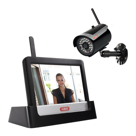
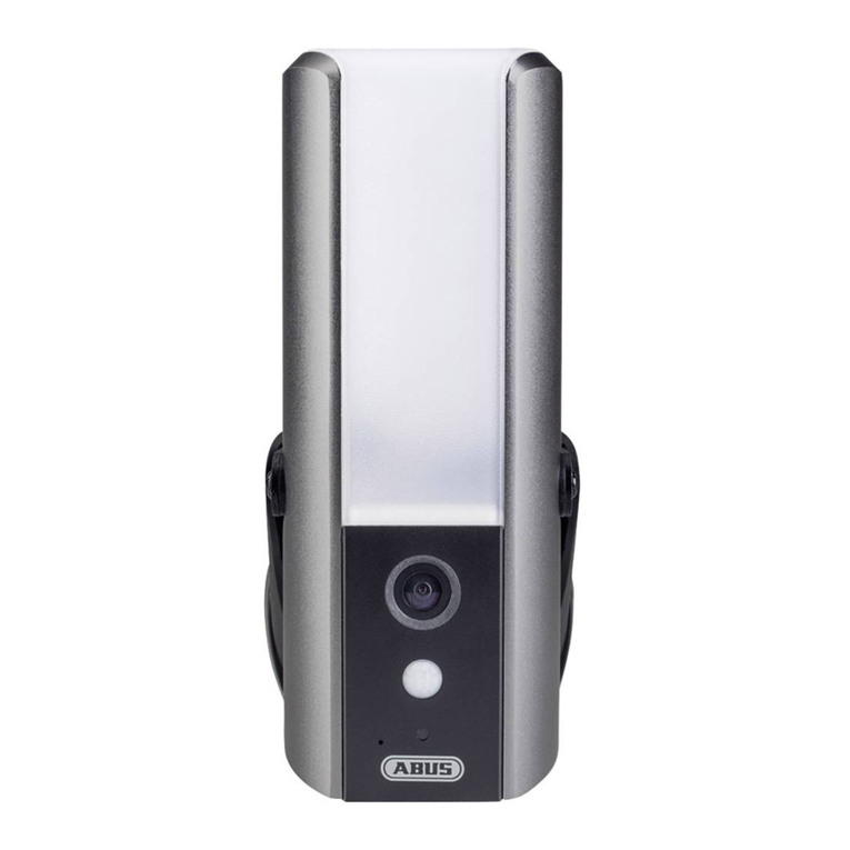
Abus PPIC46520 User manual

WLAN LICHT AUSSEN-KAMERA
W I -F I L I G H T O U T D O O R C A M E R A
QUICK GUIDE
PPIC46520 V 1.0

2
SYSTEMVORAUSSETZUNGEN
SYSTEM REQUIREMENTS
Netzwerke ohne Verschlüsselung werden nicht unterstützt.
Networks without encryption are not supported.
Aktiviere den „Standortdienst“ (z. B. „GPS“) deines Smartphones bzw. Tablets, mit dem du die Inbetrieb-
nahme durchführst. Dieser wird später benötigt, um die Netzwerke in der Umgebung anzuzeigen.
Activate the „Location service“ (e.g. „GPS“) of your smartphone or tablet with which you are
performing the startup. This will be required later to display the networks in the surrounding area.
WLAN-Netzwerk mit Passwort und Verschlüsselung.
Das WLAN-Passwort darf eine Länge von 31 Zeichen nicht überschreiten.
Wi-Fi network with password and encryption.
The Wi-Fi password must not exceed a length of 31 characters.
Der Standortdienst des mobilen Endgeräts muss aktiviert sein.
The site service of the mobile end device must be activated.
Bluetooth des mobilen Endgeräts muss aktiviert sein.
Bluetooth of the mobile end device must be activated.
Die Kamera kann nur in Verbindung mit der App2Cam Plus-App benutzt werden.
The camera can only be used in conjunction with the App App2Cam Plus.
Bei der Eingabe des WLAN-Passwortes werden folgende Sonderzeichen unterstützt.
The following special characters are possible when entering the Wi-Fi password.
Bei der Eingabe des WLAN-Passwortes sind folgende Sonderzeichen nicht möglich.
The following special characters are not possible when entering the Wi-Fi password.

3
ABUS WLAN Licht Außen-Kamera (PPIC46520)
ABUS Wi-Fi Light Outdoor Camera (PPIC46520)
LIEFERUMFANG
SCOPE OF DELIVERY
Information
Information
1
microSD-Karte
(vorinstalliert)
microSD card
(preinstalled)
Innensechskanntschlüssel
Allen key
Montagematerial
Mounting material
Kamera Fuß
Camera Base
Bohrschablone
Drilling template
Entnahmehilfe
für die microSD-Karte
Removal aid
for the microSD card
WLAN Licht Außen-Kamera
Wi-Fi Light Outdoor Camera
Antenne
Antenna
1
1
1
1
1
11
1
USB-A- auf USB-C-Kabel
USB-A to USB-C cable
1

4
KAMERA
CAMERA
Vorderseite
Front
Mikrofon
Microphone
Verschlussschraube Kamera-Fuß
Screw camera base
Objektiv
Lens
Weißlicht-LED
White light LED
Lichtsensor
Light sensor

5
Rückseite
Rear
Antennen-Anschluss (RP-SMA)
Antenna connection (RP-SMA)
Önungen für
LAN-Anschluss
Openings for
LAN connection
Önungen für
Befestigungsschrauben
Openings for
mounting screws
Önung für 230-V-Kabel
Opening for 230 V cable

6
Für Videoaufzeichnungen ist die Kamera ab Werk mit einer microSD-Karte ausgestattet. Falls du nicht die
Ringspeicher-Funktion nutzt oder mehr Speicherplatz benötigst kannst du sie gegen eine handelsübliche
microSD-Karte (max. 128 GB, mind. Klasse 10) austauschen. Für die Entnahme steht das beiliegende Ent-
nahmewerkzeug zur Verfügung. Zum Entnehmen und Einsetzen der Speicherkarte muss die Kamera vom
Strom getrennt werden. Beim Einsetzen rastet die mircoSD-Karte hörbar ein.
The camera is factory equipped with a microSD card for video recordings. If you do not use the ring
memory function or need more storage space, you can replace it with a commercially available microSD
card (max. 128 GB, min. class 10). The provided removal aid can be used to remove the card. To remove
and insert the memory card, the camera must be disconnected from the power supply. The microSD card
audibly snaps into place when fully inserted.
Unterseite (oene Abdeckung)
Bottom (open cover)
Kamera-Fuß (innen)
Camera base (inside)
microSD-Karte
microSD card
USB-C-Anschluss
USB-C Connector
Lautsprecher
Speaker
Reset-Taste
Reset button
Status-LED
Spannungsversorgung
(230V AC)
Power supply
(230V AC)
QR-Code und Erkennungsnum-
mer zur Kamera-Verizierung
QR code and identication
number for camera verication
1/2/3/6: Anschluss für
LAN-Schnittstelle
1/2/3/6: Connection for
LAN-interface
Parkposition für Kamera
während Montage
Park position for camera
during mounting
Stromkabel zur Kamera
(Anschlussblock)
Power cable to camera
(terminal block)
ACHTUNG!
IMPORTANT!

7
Falls es während der Inbetriebnahme Schwierigkeiten
gibt oder falls du die Zugangsdaten (Passwort und Si-
cherheitscode) vergessen hast, setze die Kamera
auf werkseitige Einstellungen zurück:
Öne die untere Abdeckung der Kamera mithilfe eines
Innensechskantschlüssels und drück für mindestens 5
Sekunden die Reset-Taste mithilfe eines dünnen Gegen-
stands (z. B. der Entnahmehilfe für die microSD-Karte
oder einer Büroklammer), bis die Status-LED blinkt.
If there are any diiculties during the setup or you have
forgotten the access data (password and security code),
reset the camera back to factory settings:
Open the cover on the bottom of the camera using an
allen key and press the reset button for at least
5 seconds, using a thin object (e.g. the removal
tool for the microSD card or a paper clip) until
the status LED ashes.
WERKSEINSTELLUNGEN
FACTORY RESET
Die Inbetriebnahme der Kamera per App lässt sich vor der
Montage durchführen. Vorteil: So kannst du bereits das
erste Livebild sehen und bei der folgenden Montage die
Blickrichtung der Kamera direkt feinjustieren. Verwende
während der Inbetriebnahme für die temporäre Strom-
zufuhr das beilegende USB-Kabel und verwende einen
handelsüblichen Smartphone-Ladestecker (5V, 1 A). Ver-
binde es mit dem entsprechenden Anschluss der Kamera;
dieser bendet sich an der Unterseite der Kamera hinter
der Abdeckung.
The camera can be set up using the app before installa-
tion. Advantages: You can already see the rst live image
and ne-tune the camera’s viewing direction directly dur-
ing installation. During set-up, use the included USB cable
for temporary power supply and a standard smartphone
charging plug (5V, 1 A). Connect it to the corresponding
connector of the camera; located on the bottom of the
camera behind the cover.
TEMPORÄRE STROMVERSORGUNG
TEMPORARY POWER SUPPLY

8
KAMERAMONTAGE
CAMERA INSTALLATION
Markiere mithilfe der Bohrschablone die Position der benötigten
Bohrlöcher, bohre die Löcher und setze die Dübel ein.
Using the drilling template, mark the position of the required
drill holes, drill the holes and insert the dowels.
2
Bei der Installation des Gerätes handelt es sich um eine Arbeit an der
Netzspannung. Sie muss daher von einer Fachkra nach den landesüb-
lichen Installationsvorschrien und Anschlussbedingungen durch-
geführt werden. Bei der Montage muss die anzuschließende elektrische
Leitung spannungsfrei sein. Daher als Erstes den Strom abschalten.
Unbedingt darauf achten, dass während der gesamten Montage der
Leitungsschutzschalter abgeschalten bleibt. Wenn möglich sicherstellen,
dass dieser LS-Schalter nicht zugänglich ist. Im Anschluss die Span-
nungsfreiheit mit einem geeigneten Messgerät allpolig feststellen.
Installation of the device involves work on the mains power supply.
It must therefore be carried out by a specialist in accordance with
the national installation regulations and connection requirements.
Electrical wires must be disconnected from the power supply during
installation. Therefore, switch o the power rst. Make sure that the
circuit breaker remains switched o during the entire installation
process. If possible, ensure that this circuit breaker is not accessible. Af-
terwards, determine the absence of voltage at all poles using a suitable
measuring device.
1
OFF
ACHTUNG!
IMPORTANT!
Auf der Rückseite des Kamera-Fußes sind drei kleine Önungen ange-
deutet, für die drei Adern des Stromkabels, das die Kamera regulär mit
Spannung versorgen soll. Führe die drei Adern an den entsprechenden
Punkten durch die Gummiabdichtung. Achte auf die passende Kabel-
länge für den folgenden Anschluss an die Lüsterklemme im Fuß der
Halterung. Montiere den Fuß der Halterung mithilfe der beiliegenden
Schrauben an der vorgesehenen Kamera-Position.
On the back of the camera base, three small holes are indicated for the
three wires of the power cable that is supposed to supply the camera
with regular voltage. Feed the three wires through the rubber seal at
the through the rubber seal at the corresponding points. Make sure
that the cable length is suitable for the following connection to the
screw terminal block in the base of the mount. Install the base of the
mount in the intended camera position using the supplied screws.
3

9
Nimm die per Stromkabel verbundene Kamera nun aus der Parkposition
und schraube sie an den Fuß der Halterung. Achte dabei darauf, dass
keine Kabel gequetscht werden.
Now take the camera connected by power cable out of the parking
position and screw it back onto the base of the mount. Make sure
that no cables are pinched.
7
5
Der Fuß der Halterung verfügt über eine sogenannte Parkposition
für die Kamera. Setze die Kamera für die nachfolgende Verkabelung
in die Parkposition.
The base of the mount has a so-called parking position for the camera.
Place the camera in the parking position for the following cabling.
4Verbinde den zuvor durch den Fuß geführten stromführenden Leiter,
Neutralleiter und den Schutzleiter mit der Lüsterklemme.
Tipp: Die Lüsterklemme lässt sich aus deren Halterung herausnehmen.
L = Stromführender Leiter (meistens schwarz oder braun)
N = Neutralleiter (meistens blau)
= Schutzleiter (grün-gelb)
Connect the live conductor, neutral conductor and the PE conductor that
were previously passed through the base to the screw terminal block.
Tip: The screw terminal block can be removed from its holder.
L = Live conductor (usually black or brown)
N = Neutral conductor (usually blue)
= Protective earth conductor (green-yellow)
6Wichtig! Verbinde den (grün-gelben) Schutzleiter, der ab Werk bereits
mit der Abdeckung des Fußes verbunden ist, nun noch mit der Lüster-
klemme im Kamera-Fuß. Bei Bedarf: Für die Ader die kleine Füh-
rungsschiene im Kamera-Fuß verwenden. Verbinde anschließend das
Stromkabel der Kamera über den (schwarzen) Stecker korrekt mit dem
entsprechenden Anschluss im Kamera-Fuß. Beachte: Der Stecker ist in
der korrekten Position eingerastet, um ein versehentliches Ablösen
während der weiteren Montage zu verhindern. Bei einer Demontage
entsprechenden Klemmmechanismus berücksichtigen, um die Verkabe-
lung nicht zu beschädigen.
Important! Connect the (green-yellow) protective earth conductor,
which is already connected to the cover of the foot ex factory, to the
terminal block in the camera foot. If necessary: Use the small wire rail
in the camera foot for the wire. Then connect the power cable of the
camera via the (black) plug correctly to the connector in the camera
foot.Note: The plug is locked in the correct position to prevent acciden-
tal disconnection during further installation. When disassembling, pay
attention to the appropriate clamping mechanism to avoid damaging
the cabling.
10
10
Die Kamera ist nun voll funktionsbereit. Versichere dich, dass niemand
an anderen oenen Stromleitern im Haus hantiert und schalte an-
schließend die Spannungsversorgung für die Kamera ein. Nach ca. 60
Sekunden kannst du wieder auf das Livebild zugreifen, falls du die In-
betriebnahme per App bereits zuvor durchgeführt hast. Falls noch nicht
geschehen: Starte jetzt die Erstinbetriebnahme per App.
The camera is now fully functional. Make sure that no one is handling
other open power lines in the house and then switch on the power
supply for the camera. You can access the live image again aer a prox.
60 seconds if you have already carried out set-up via the app. If not
already done: Now start the initial set-up via the app.
9
8
Befestige die Antenne am Anschluss auf der Rückseite der Kamera.
Attach the antenna to the connector on the back of the camera.
ON
Um die genaue Blickrichtung der Kamera einzustellen: Löse ein klein
wenig die drei Schrauben am Bügel, um die Kamera zu schwenken und/
oder zu neigen. Tipp: Nimm zum Feinjustieren das Livebild in der App
zur Hilfe.
To adjust the exact viewing direction of the camera: Slightly loosen the
three screws on the bracket to tilt and/or swivel the camera. Tip: Use
the live image in the app for ne-tuning.

11
INBETRIEBNAHME
INITIAL START-UP
Die folgenden Abbildungen entstammen der iOS-App.
Der Prozess mit der Android-App läu in den gleichen Schritten.
The following illustrations are from the iOS app.
The process with the Android app follows the same steps.
Bluetooth des Smartphones/Tablets muss aktiviert sein.
Bluetooth of the smartphone / tablet must be activated.
Installation App2Cam Plus und Inbetriebnahme
Installation of App2Cam Plus and start-up
Starte App2Cam Plus und wähle „Neues Gerät hinzufügen“
aus, um die Inbetriebnahme zu starten.
Launch App2Cam Plus and select
"Add new device" to start the start-up.
2
Lade App2Cam Plus auf dein Smartphone oder Tablet
Download App2Cam Plus to your smartphone or tablet
1
App
- App2Cam Plus -
iOS
Apple App Store
Android
Google Play Store

12
Für eine optimale Inbetriebnahme müssen die Kamera und das Smartphone/Tablet möglichst nahe
nebeneinander sein, maximal in 3 Meter Entfernung.
For optimal startup, the camera and the smartphone/tablet must be as close as possible next to each
other, at a maximum distance of 3 meters.
3a
4
Option 1: Scanne den QR-Code, der sich im Kamera-Fuß be ndet.
Option 1: Scan the QR code located in the camera base.
Option 2: Tippe auf die Schalt äche "Gerät manuell hinzufügen"
und wähle anschließend aus der Liste dein Kameramodell aus.
Option 2: Tap on the "Add device manually"
button and select your camera model from the list.
Wähle „Inbetriebnahme via Bluetooth“ aus.
Select "Setup via Bluetooth".
3b

13
Für eine optimale Inbetriebnahme müssen die Standortdienste in den Einstellungen aktiviert sein.
The site services must be activated in the settings fot optimal operation.
7
Falls noch nicht geschehen: Aktiviere Bluetooth in den Einstellungen deines
mobilen Endgerätes. Tippe anschließend auf „Weiter“.
If not already done: Activate Bluetooth in the settings of the mobile device.
Then tap on "Next".
Wähle deine Kamera anhand der Erkennungsnummer aus. Die Erkennungs-
nummer (DID) ndest du beigelegt in der Verpackung. Alternativ im Kamera-
Fuß, unterhalb des QR-Codes. Tippe anschließend auf "Weiter".
Select your camera by its identi cation number. The identi cation number
(DID) of your camera can be found under the QR code that is located on your
camera and in the packaging. Then tap on "Next".
5
6
Versorge die Kamera jetzt mit Strom, wenn nicht schon geschehen, und
warte 2 Minuten bis die Status-LED der Kamera (hinter unterer Abdeckung)
2x kurz und 1x lang blinkt. Tippe anschließend auf "Weiter".
Now supply the camera with power, if not already done, and wait 2 minutes
until the status LED of the camera (behind bottom cover)
ashes 2x short and 1x long. Then tap on "Next".

14
Network 1
Siehe Systemvoraussetzungen „WLAN-Netzwerk“ und „Sonderzeichen“.
See system requirements „Wi-Fi network“ and „special characters“.
Das Admin-Passwort kann nach der Installation in den Einstellungen der Kamera geändert werden.
The admin password can be changed in the camera settings a er installation.
9
Network 1
Wähle dein Heimnetzwerk/WLAN aus,
indem du die Kamera dauerha betreiben willst.
Tippe anschließend auf "Weiter".
Select your home network/Wi-Fi,
where you want to operate the camera permanently.
Then tap on "Next".
Gib das Passwort deines Netzwerkes ein.
Tippe anschließend auf "Weiter".
Enter the password of your network.
Then tap on "Next".
Vergib nun einen Sicherheitscode und ein Admin-Passwort.
Diese müssen bei der Einrichtung per Bluetooth identisch sein.
Tippe anschließend auf "Weiter".
Now assign a security code and an admin password.
These must be identical during Bluetooth setup.
Then tap on "Next".
8
10

15
Lichtkamera [PPIC46520]
Eingangsbereich
11
Schritte für eine alternative Inbetriebnahme findest du in der Bedienungsanleitung.
You can nd additional steps for the „Alternative installation“ in the operating instructions.
Die Kamera startet nun neu. Dies kann bis zu 60 Sekunden dauern.
The camera will now restart. This can take up to 60 seconds.
Für das bestmögliche Kamera-Erlebnis empfehlen wir,
die Kamera immer mit der neuesten Firmware zu betreiben.
For the best possible camera experience, we recommend to
operate the camera always with the latest rmware.
Die Inbetriebnahme per App ist nun abgeschlossen. Die App zeigt
nun die Kamera-Übersicht mit einem ersten Vorschaubild der
Sicherheitskamera. Tippe im Vorschaubild auf das Play-Symbol,
um das erste Livebild anzuzeigen. In seltenen Fällen, z. B. bei
zu schlechtem Empfang, zeigt die App das Symbol "fehlende Ver-
bindung". Tippe darauf, um die Liveansicht zu ö nen.
The setup via app is now completed. The app now shows the ca-
mera overview with a rst preview image of the security camera.
Tap the play icon in the preview image to display the rst live
image. In rare cases, e.g. if the network connection is too poor,
the app displays the "missing connection" icon. Tap on it to
open the live view.
13
Lichtkamera [PPIC46520]
Eingangsbereich
Lichtkamera [PPIC46520]
Eingangsbereich
12

16
Lichtkamera [PPIC46520]
Eingangsbereich
Tippe in der Kamera-Übersicht auf das Zahnrad-Symbol,
um Einstellungen vorzunehmen, die die App betreen.
Tap the gear icon in the camera overview,
to make settings that aect the app.
14
Den aktuellen Firmware-Stand deiner Kamera und bereitstehende Updates findest du unter "Kamera-
Übersicht" -> "Liveansicht" -> "Kameraeinstellungen" -> "Geräte" -> "Firmware-Update suchen".
The current firmware version of your camera and available updates can be found under "Camera
Overview" -> "Live View" -> "Camera Settings" -> "Devices" -> "Search Firmware Update".
Alle gezeigten Screenshots entstammen der iOS-App. Die Android-App enthält eine leicht
abweichende Anordnung, Beschriung und Funktionalität.
All screenshots and icons shown here are from the iOS app.
There may be some deviations in the labels, design or functionality when using Android devices.
Lichtkamera [PPIC46520]
Eingangsbereich
Tippe in der Kamera-Übersicht auf das Symbol
für Aufzeichnungen, um den Speicher aufzurufen.
Tap the recordings icon in the camera
overview to access the storage.
15

17
Die Liveansicht in App2Cam Plus
The live view in App2Cam Plus
APP2CAM PLUS
APP2CAM PLUS
Lichtkamera [PPIC46520]
Einstellungen für diese Kamera vornehmen
Settings for this camera
Gegensprechfunktion
Zum Aktivieren des Mikrofons deines End-
gerätes und des Lautsprechers an deiner
Kamera drücke dauerha auf das Mikrofon-
Symbol. Die Verbindung zur Kamera bleibt
oen, solange du das Symbol gedrückt
hältst.
Intercom function
You can use the microphone of the mobile
end device to communicate through the
camera intercom. Press and hold the
symbol in order to activate the intercom
function. The transmission is deactivated
as soon as you release the symbol.
Schnappschuss erstellen
Create a snapshot
Audio aktivieren/deaktivieren
(für Aufzeichnungen mit/ohne Ton,
siehe Kameraeinstellungen)
Enable/disable audio (for recordings
with/without audio, see camera settings)
Sirene aktivieren/deaktivieren
Activate/deactivate siren
Manuelle Aufnahme starten
Start manual recording
Menü Licht-Steuerung önen
Open Light Control menu
Alarm ist aktiv
Die Kamera zeichnet bei erkannten Bewegungen
auf und versendet Nachrichten (Push oder E-Mail),
wenn in den Kameraeinstellungen die Funktionen
grundsätzlich aktiviert sind.
Alarm is active
The camera records when motion is detected and
sends notications (push or e-mail), if the functions
are basically activated in the camera settings.
Alarm ist deaktiviert
Die Kamera zeigt ein Livebild, führt aber keine weite-
ren Aktionen bei erkannten Bewegungen durch.
Alarm is deactivated
The camera displays a live view but does not carry
out any other actions when motion is detected.

ABUS | Security Center GmbH & Co. KG
abus.com
Linker Kreuthweg 5
86444 Ang
Germany
Tel: +49 8207 959 90-0
Fax: +49 8207 959 90-100
sales@abus-sc.com
abus.com/products/
PPIC46520
Die komplette Bedienungsanleitung sowie weitere Informationen stehen dir auf der Website von
ABUS zur Verfügung: Einfach den QR-Code scannen oder die Web-Adresse eingeben, schon önet
sich die Produktseite mit dem Bereich Downloads.
The complete operating instructions and further information are available on the ABUS website:
Simply scan the QR code or enter the web address to open the product page with the Downloads
section.
Le mode d'emploi complet ainsi que d'autres informations sont à votre disposition sur le site
Internet d'ABUS : Il sut de scanner le code QR ou d'entrer l'adresse web pour que la page du
produit s'ouvre avec la section Téléchargements.
De volledige gebruiksaanwijzing en verdere informatie zijn beschikbaar op de website van ABUS:
Scan gewoon de QR-code of voer het webadres in om de productpagina met de sectie Downloads
te openen.
Den komplette brugsanvisning og yderligere oplysninger ndes på ABUS' hjemmeside: Du skal blot
scanne QR-koden eller indtaste web-adressen for at åbne produktsiden med området Downloads.
El manual de instrucciones completo y más información están disponibles en el sitio web de ABUS:
Basta con escanear el código QR o introducir la dirección web para abrir la página del producto con
la sección de descargas.
Den fullständiga bruksanvisningen och ytterligare information nns på ABUS webbplats: Skanna QR-
koden eller skriv in webbadressen för att öppna produktsidan och delen Downloads.
Le istruzioni per l'uso complete e ulteriori informazioni sono disponibili sul sito web di ABUS: È
suciente scansionare il codice QR o inserire l'indirizzo web per aprire la pagina del prodotto
con la sezione Downloads.
Kompletna instrukcja obsługi oraz dalsze informacje dostępne są na stronie internetowej rmy ABUS:
Wystarczy zeskanować kod QR lub wpisać adres internetowy, aby otworzyć stronę produktu z sekcją
Downloads.
Other manuals for PPIC46520
3
Table of contents
Other Abus Security Camera manuals

Abus
Abus IPCB74521 User manual

Abus
Abus TVCC12020 User manual

Abus
Abus IPCS28581A User manual

Abus
Abus IPCS84510 User manual

Abus
Abus TVCC12010 User manual

Abus
Abus IPCS84551 User manual

Abus
Abus IPCB42501 User manual

Abus
Abus HDCC68550 User manual

Abus
Abus IPCS58571A User manual

Abus
Abus IPCS84530 User manual

Abus
Abus TVCC34020 User manual

Abus
Abus HDCC62551 User manual

Abus
Abus eyseo TV7144 User manual

Abus
Abus IPCB62515A User manual

Abus
Abus TVCC34000 User manual

Abus
Abus TVCC80000 User manual

Abus
Abus TVAC16010A User manual

Abus
Abus TVAC19000C User manual

Abus
Abus HDCC32500 User manual

Abus
Abus Eyseo TV7220 User manual