Abus TV7230 User manual

Pan/Tilt network camera
Installation instructions
TV7230
TV7240

2
Preface
Dear Customer,
Thank you for purchasing this Pan/Tilt Network Camera of the DIGI-LAN series from Security-Center. You
made the right decision in choosing this state-of-the-art technology,
which complies with the current standards of domestic and European regulations. The CE has been proven
and all related certifications are available from the manufacturer upon request.
To maintain this status and to guarantee safe operation, it is your obligation to observe these operating
instructions! In the event of questions, please contact your local specialist dealer.
This PAN/TILT network camera is used for object surveillance. The recorded video signals are transmitted to
a computer digitally via the connected network. The computer software permits simultaneous recording of up
to 16 connected video signals. Data storage is subject to local national data-protection guidelines. Via the
Internet Explorer, you have worldwide access to installed cameras (password-protected).
Precautions
The PAN/TILT network camera and connected components must be kept free of moisture (cellars and similar
surroundings are to be strictly avoided). Use of this product for other than the described purpose may lead to
damage of the product. Other hazards such as short-circuiting, fire, electric shock, etc., are also possible.
The equipment is designed for operation using a Class 2 5V DC transformer. No part of the product may be
changed or modified in any way. Connection to the public power network is subject to country-specific
regulations. Please be aware of applicable regulations in advance.
To avoid fire and injury, please observe the
following:
Securely fasten the device at a dry location in
the building.
Ensure sufficient air circulation.
Do not expose the device to temperatures less
than 0°C or more than 35°C.
The device is designed for indoor use only.
Humidity must not exceed 90% (non-
condensed).
Ensure that the voltage is disconnected when
performing work on the device.
Please observe the following regulations to
ensure trouble-free operation of your
device.
The PAN/TILT network camera is supplied by a
12VDC transformer.
The transformer should be connected to the
230VAC building mains by means of a
separate, electrically protected line.
Connection work to the building mains is
subject to country-specific regulations
General:
Improper or careless installation work may lead to faults and poor image quality. Therefore please read the
instructions very carefully and follow the installation instructions for lines and components precisely.
The manufacturer reserves the right to make technical modifications at any time.

3
Before using this product
The use of surveillance equipment may be forbidden by law in some countries. This PAN/TILT network
camera is not only high-quality web camera but can also be used as part of a flexible surveillance
system. Before using this equipment, make sure that all your surveillance activities are completely
legal.
Before installation, check the product for completeness (page 5: Scope of delivery). Read the
installation instructions before installing the PAN/TILT network camera. Read the “Hardware
Installation” chapter carefully and follow the instructions contained in it to avoid damage caused by
faulty assembly or incorrect installation. This will ensure that the equipment goes into operation
correctly for the intended purpose.
Appendixes A and B contain possible solutions to problems occurring during installation and
configuration.
The installation instructions describe different usage scenarios of the PAN/TILT network camera.
Sections marked with contain special hints and advice for the user. Ignoring this advice can
result in damage to the equipment or injury.

4
Contents
Preface2
Precautions........................................................................................................................... 2
Before using this product ........................................................................................................ 3
Contents............................................................................................................................... 4
Scope of delivery ................................................................................................................... 5
Hardware installation .............................................................................................................. 6
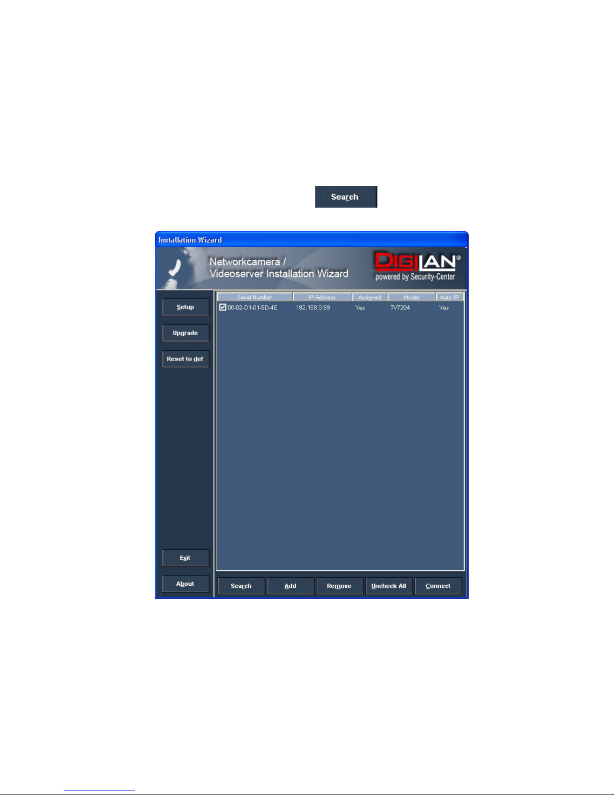
First access to PAN/TILT network camera.................................................................................. 7
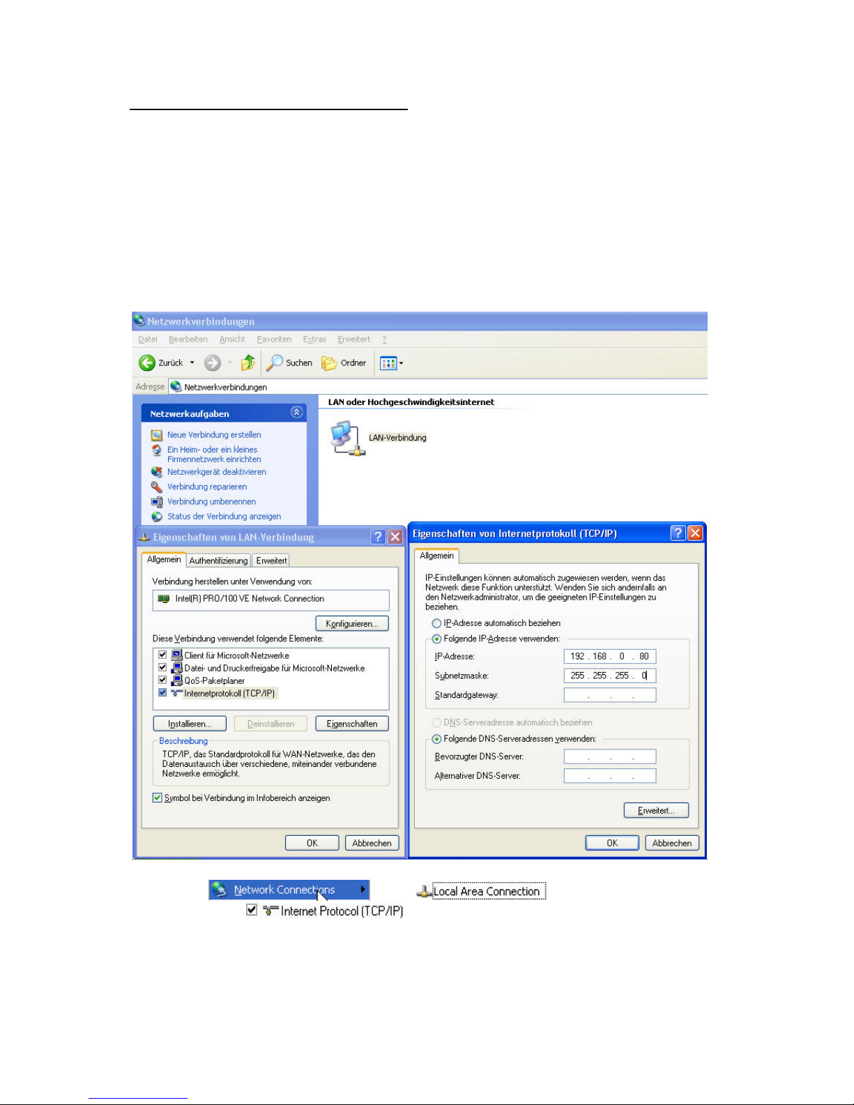
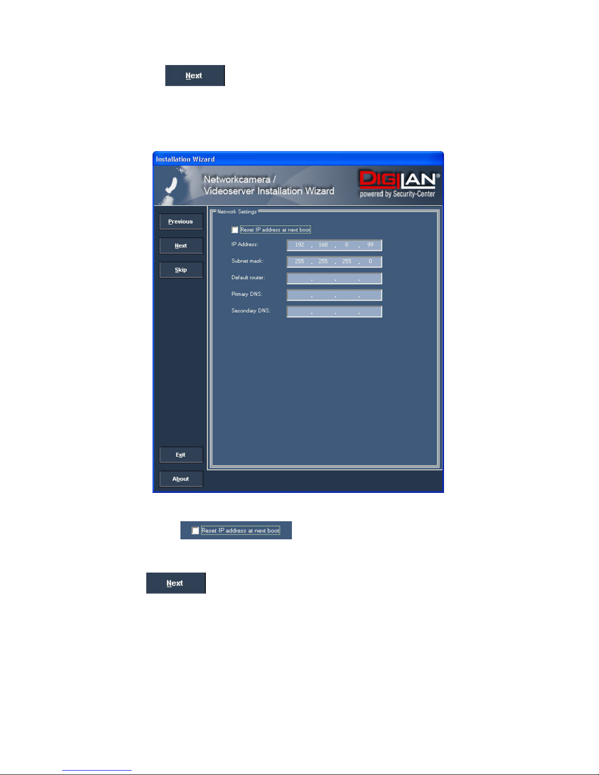
Setting the IP address....................................................................................................................7
Note: ...............................................................................................................................................9
Access to the network camera via the Internet Explorer............................................................. 12
Defining a password to prevent unauthorised access ............................................................... 12
Changing the administrator password........................................................................................ 13
Installing the plug-in .................................................................................................................... 14
Basic user functions ............................................................................................................. 15
Main window and camera view................................................................................................... 15
Digital Zoom and Snapshot ........................................................................................................ 16
Client Settings ............................................................................................................................. 18
Administrator settings ........................................................................................................... 20
Configuration / video ................................................................................................................... 20
Protecting the PAN/TILT network camera with a password ...................................................... 21
Setting up a surveillance application .......................................................................................... 22
Updating the software version .................................................................................................... 22
System configuration............................................................................................................ 23
System......................................................................................................................................... 24
Security........................................................................................................................................ 24
Network........................................................................................................................................ 25
WLAN configuration .................................................................................................................... 27
Enable the DDNS function.......................................................................................................... 29
Access list.................................................................................................................................... 30
Video and audio .......................................................................................................................... 31
Email and FTP............................................................................................................................. 34
Motion sensor.............................................................................................................................. 35
Application ................................................................................................................................... 36
Viewing the log file ...................................................................................................................... 38
Viewing parameters .................................................................................................................... 38
Maintenance................................................................................................................................38
Appendix ............................................................................................................................ 39
A. Troubleshooting ...................................................................................................................... 39
B. Frequently asked questions (FAQ) ........................................................................................ 40
C. URL commands of the network camera ................................................................................ 42
D. Technical data ........................................................................................................................ 55
E. Licence information ................................................................................................................ 56

5
Scope of delivery
PAN/TILT network camera
TV7230 / 7240
Antenna (only TV7230)
Transformer
Wall / Ceilling mount bracket
Software CD
Installation instructions (on CD)

6
Hardware installation
When you switch on, the red LED on the front lights up and the start procedure begins. During the
start procedure, the blue, red and green LED are all active. This state continues until an IP address is
defined. After you define the IP address, the green LED flashes once a second. For troubleshooting
hints, see Appendix.
The PAN/TILT network camera first tries to address the wired Ethernet. If it cannot reach this, the
camera tries to reach the wireless network (WLAN). During the search and connection process to the
wireless access point, the red LED on the network camera flashes once a second. The red LED
remains in this state until the connection to an access point is established. During operation in the
WLAN or wired mode, the green LED flashes constantly once a second to show this activity.
Installation in the Ethernet
Make sure that the camera is directly connected to a PC (cross-link cable) or via a switch/hub to the
network. Now connect the network adapter of the camera to the mains network. When the camera is
correctly connected to the network, the blue LED on the front lights constantly. If no network is
available, the camera switches to WLAN mode.
Installation in the WLAN
If the camera is supplied with electricity and no Ethernet is available, the camera switches to WLAN
mode and searches for an access point with the name “default”. This name is known as the SSID
(Service Set Identifier). If an access point with the SSID “default” is found, the LED on the front lights
blue.
If connection with the basic settings (SSID: default) is not successful, connect the camera via a cable
to the wired network and configure it.
Make sure that all accessories and articles
listed above are present in the scope of
delivery. Depending on application, an Ethernet
cable may be required. This Ethernet cable
must meet the specifications of UTP Category
5 (CAT 5) and must not be longer than 100
meters.
To prevent the risk of electric shock, first connect the socket of the transformer to the
PAN/TILT-network camera before inserting the transformer into the mains socket.
Consult your dealer for the correct installation of peripheral devices.

7
First access to PAN/TILT network camera
Setting the IP address
To set the IP address of the camera:
Use a network cable to connect the PAN/TILT network camera to your computer network.
(The simplest way is to connect the PAN/TILT network camera direct to your PC using a cross-link
cable.)
If your PC is not yet integrated into a network, you first have to configure it for the network application.
Do this by opening the Properties page for your network.
(This also applies if the camera is connected to the PC via a hub or switch.)
1. Click , select and open the Properties
page of the .
2. Enter a fixed IP address and subnet mask
(e.g.: 192.168.0.95 and as subnet mask 255.255.255.0).

8
The network connection of your PC is now configured.
3. Now start the Installation Wizard from the software CD supplied.
4. Follow the installation instructions of the Installation Wizard.
5. If installation is successful, start the program under Programs/Installation Wizard.
6. Following the program start, the Installation Wizard automatically searches for a connected
network camera.
7. If no camera is found in the first search, click for a new search.
Note: If no camera is found via the manual search, change the network settings of your PC as
described in the instructions.

9
8. Select one of the camera models found.
9. Click to enter camera setup mode. If you have to enter a password, use the
device serial number (no spaces, uppercase letters only). You can change the hostname, the
administrator password and the date/time settings of the camera. If you cannot access the
settings, check the IP addresses of your network adapter and your network camera. The IP
addresses must be in the same subnet area. If necessary, change the IP address of the
network adapter (page 7).
Note:
The IP addresses shown in the “Current IP Address” field reflect those on the local network. They may
be from the DHCP server. If there is no DHCP server, the camera will try to find a free IP address (this
takes from 15 seconds to 3 minutes, depending on the LAN status). The method of finding an IP
address is seeking from 192.168.0.99, to 192.168.0.254. If any of the address inside this range is free,
the network camera will be assigned to this IP address, and its subnet mask would be 255.255.255.0.
If none of the addresses is free, the network camera will try the range from 192.168.0.2 to
192.168.0.98. After an IP address is assigned to the camera, the green status LED blinks (1/s).
Note: If no camera is found via the manual search, change the network settings of your PC as
described in the instructions.

10
10. Now click to change the IP address of your network camera.
If you use a router in your network, enter this IP address (gateway) in the Default Router
field. For a Cross link connection from the camera to the PC you have to type in an IP address
in the same subnet (e.g. 192.168.0.1).
11. If you disable , you do not have to reassign the IP address of this
camera following a power failure. Otherwise, you have to reassign the IP address after every
camera restart.
12. Click .

11
Press “Skip” to leave the “Wireless setting” unchanged this time. For further information please read
chapter “WLAN configuration”.
13. Follow the instructions on the screen to save or change your settings.
14. Click to add a network camera direct via the IP address or its domain name.
You need this only if the camera was not found by the automatic search.
15. Click or to remove one or all network cameras from the menu.
16. Click to set up a link to the selected network camera via the Internet Explorer.
The Installation Wizard is finished. Click to change your settings. Click
to save your input and transfer it to the selected device.

12
Access to the network camera via the Internet Explorer
Defining a password to prevent unauthorised access
When delivered, no administrator password is defined for the PAN/TILT network camera.
The PAN/TILT network camera asks for this number at the start of operation. For security reasons, the
administrator should define a new password immediately. After the new administrator password is
stored, the PAN/TILT network camera asks for the user name and password every time it is accessed.
The administrator can define up to twenty (20) user accounts. Every user has access to the PAN/TILT
network camera, but not to the system configuration. Some system-critical functions are reserved for
the administrator, such as system configuration, user administration and upgrading software
programs. The administrator’s user name is always root and cannot be changed. Following a
password change, the browser displays an authentication window and asks for the new password.
After changing the password, you cannot restore the original administrator password. Your only option
is to reset all default factory settings/parameters.
To enter a password:
Open the Internet Explorer and enter the IP address of the camera (e.g.: <http://192.168.0.99>).
You are prompted for authentication:
ÎYou are now connected with the PAN/TILT network camera and can see a video stream.
Note: It may happen that your PC’s security settings prevent a video stream. You can change
the security settings to a lower level under “Tools/Internet Options/Security”. Make sure you enable
Active X Control Elements and Downloads.

13
Changing the administrator password
Click “Configuration” and then “Security”.
Under “Root password”, enter the administrator password and confirm it under Confirm password.
Click .
The new administrator password is saved.
Click “HOME” in the column on the left to exit configuration.

14
Installing the plug-in
When you first access the PAN/TILT network camera under Windows, the web browser may ask for
the installation of a new plug-in for the PAN/TILT network camera. This query depends on the Internet
security settings of your PC. If the highest security level is set, the PC will refuse any installation and
any attempt at execution. This plug-in is used for video display in the browser. To continue, click
. If the web browser prevents continuation of the installation, open the Internet security
settings and reduce the security level or consult the IT administrator or network administrator.

15
Basic user functions
Main window and camera view
The view of the main page consists of three parts:
Configuration: You can configure the camera with these steps.
Camera view:Camera video stream
Pan/Tilt control buttons: These buttons provide the commands to control the viewing angle of the
network camera.
Click the configuration link on the left of the picture to open the configuration page.

16
Digital Zoom and Snapshot
Click the magnifying glass under camera view. The control field for digital zooming appears. Disable
the Disable Digital Zoom box and change the zoom factor with the slider.
Click “Snapshot”. The web browser displays a new window containing the snapshot. To save the
snapshot, either left-click it and then click the diskette icon or right-click it and select Save from the
context menu.
Playback options
“Play” The option will connect to the network camera. The button is the same one as “Pause”
“Pause” The option will pause the video, but the connection remains.
“Stop” The option will disconnect the network camera connection.
“Play volume” Click on this button then a slider appears to adjust the audio volume.
“Mute” To disable audio at the client side.

17
The pan/tilt control buttons
The direction buttons are for Left, Right, Up, Down and Home functions. The Home function moves the
camera head to a defined “Home” position.
Another way to change the viewing angle of the camera is by using the mouse pointer and click
directly on a position on the video picture.
“Go to” Once the Administrator has determined the preset positions, the user can aim the camera
using this control.
“Pan Speed” The selection sets the moving speed of the “Left” and “Right” commands.
“Tilt speed” The selection sets the moving speed of the “Up” and “Down” commands.
“Pan” This button commands the camera to pan from the current position to the left-most and then to
the right-most position. After panning the camera returns to the original position.
“Patrol” This button commands the camera to patrol between the preset positions on the Patrol list,
which can be modified on the “Camera control page”. After one patrol cycle the camera returns to the
original position.
“Stop” This will stop the “Auto Pan” command or “Auto Patrol” command.

18
Client Settings
When you first access the Connection Type page under Windows, the web browser asks for the
installation of a new plug-in. This plug-in was registered at certification and can be used to change
parameters on the Client settings page. To install the plug-in, click . If the web browser
prevents continuation of the installation, open the Internet security settings and reduce the security
level or consult the IT administrator or network administrator.
Two settings are available on the Client-Settings page. Under “Media Options”, you can disable the
audio- or video function. Under “Protokoll Options”, you can select a transmission protocol for data
transfer between the client and the server. Two protocol options are available for optimising the
application: UDP and TCP.
The UDP protocol gives you a larger number of realtime audio and video streams. However, some
data packets can be lost due to the large data volume in the network. Pictures can be unclear. The
UDP protocol is recommended if you have no special requirements.
With the TCP protocol, fewer data packets are lost and the video display is more accurate. The
disadvantage of this protocol is that the realtime stream is worse than with the UDP protocol.

19
The selection of the client is normally recommended in the following order: UDP – TCP. When the
PAN/TILT network camera has been successfully connected, the “Protocol Options” box shows the
selected protocol. The selected protocol is registered in your PC and used for the next connection.
After changing the network environment or if you want to search again for the PAN/TILT network
camera using the web browser, select the UDP protocol manually, save it and then return to “HOME”
to set up the connection again.
<url> http://<network camera IP>/client.html
Network Camera is the original IP address or the hostname of the PAN/TILT network camera.

20
Administrator settings
Configuration / video
Best performance is produced by
the maximum frame rate with best
video quality and minimum
network bandwidth. The three
factors “Max frame rate”, “Constant
bit rate” and “Fixed quality” on the
video configuration page are
interrelated.
Mobile access to the PAN/TILT network camera
Many modern mobile telephones support access to MPEG4 videostream and GSM-AMR audio data.
Due to restricted bandwidth, only a maximum resolution of 176x144 pixels is supported. You should
therefore select “Configuration for mobile access”, and all necessary parameters are adjusted
accordingly. The player to play the RTSP-stream must support MPEG4-Simple Profile (e.g. Packet
Video Player).
For high frame rates
To obtain a good visual realtime effect (more than 20 frames/s), the network bandwidth must be
sufficiently large. If the network bandwidth is higher than 1 Mbps, the value for the “Constant bit rate”
must be set to 1000Kbps or 1200Kbps and the “Fixed quality” to the highest quality. In the PAL
system, the maximum frame rate is 25, and in the NTSC system, 30 frames per second. If your
network bandwidth is more than 384Kbps, you can fix the bit rate according to your bandwidth and the
maximum frame rate to 25 or 30 fps (frames per second). If the pictures in your environment are
changed drastically, you can reduce the maximum frame rate to 20 frames per second to set the data
transmission rate lower. This gives you a better video quality, and the human eye cannot distinguish
between 20, 25 and 30 frames per second. If the network bandwidth is less than 384 Kbps, adjust the
“Constant bit rate” according to the bandwidth and try to get the best performance by fine-tuning the
“Max frame rate”. In a “slow” network, a high frame rate results in unclear, distorted images. Another
way to improve quality is to select “160x120” in the “Size” option, or “320x240” for a larger view of the
pictures. Video quality also depends on the number of users in the network. Performance can also be
affected by a bad connection and by a restriction of the network burst.
Other manuals for TV7230
1
This manual suits for next models
3
Table of contents
Other Abus Security Camera manuals

Abus
Abus TVIP42562 User manual

Abus
Abus TVIP51500 User manual

Abus
Abus HDCC68550 User manual

Abus
Abus TVAC19000C User manual

Abus
Abus PPIC90000 User manual

Abus
Abus TVIP11560 User manual

Abus
Abus TVIP70000 User manual

Abus
Abus TVAC19000C User manual

Abus
Abus IPCB42501 User manual

Abus
Abus TVHD75500 User manual

Abus
Abus TVAC19100B User manual

Abus
Abus TVIP10005B User manual

Abus
Abus HDCC71510 User manual

Abus
Abus Ecoline TV7100 User manual

Abus
Abus IPCB54511A User manual

Abus
Abus TVIP61550 User manual

Abus
Abus IPCB71500 User manual

Abus
Abus TVIP20000 User manual

Abus
Abus TVIP82900 User manual

Abus
Abus TVAC16010A User manual