Accelleron A136-H radial User manual

Purpose
The ssembly instructions explin how
the turbochrger is fited to the engine
correctly nd without ny helth nd
sfety risks.
Target group
The ssembly instructions re intended
for engineers nd mechnics responsi-
ble for fiting the turbochrger
on the engine.
Assembly Instructions
Turbocharger /
A136-H radial
Original assembly instructions – English
This document is valid for:
A136-H


Assembly Instructions / A136-H
Table of contents
© Copyright 2022 Accelleron Industries. All rights reserved. HZTL455311P0038_EN Rev. C May 2022
Assembly Instructions / A136-H
1 Introduction ................................................................................... 2
1.1 Purpose of the assembly instructions .................................................................... 2
1.2 Definition of target group ...................................................................................... 2
1.3 Symbols, definitions .............................................................................................. 2
1.4 Definition of warning, caution, note ....................................................................... 3
1.5 Definition of mandatory signs ................................................................................ 4
1.6 Definition of pictograms ........................................................................................ 4
2 Safety............................................................................................ 5
2.1 Introduction.......................................................................................................... 5
2.2 Lifting of loads...................................................................................................... 6
2.3 Occupational safety.............................................................................................. 7
3 Turbocharger weight and transportation.......................................... 9
4 Installing the turbocharger ............................................................ 10
4.1 Inserting gaskets into the bracket......................................................................... 10
4.2 Fitting threaded rods............................................................................................. 11
4.3 Placing the turbocharger on the bracket............................................................... 12
4.4 Fastening the turbocharger with a standard nut .................................................... 13
4.5 Connecting the turbocharger................................................................................ 13
5 Storage of new turbochargers and spare parts ............................... 14
6 Further information........................................................................ 17

Assembly Instructions / A136-H
1 Introduction / 1.1 Purpose of the assembly instructions
© Copyright 2022 Accelleron Industries. All rights reserved. HZTL455311P0038_EN Rev. C May 2022
1 Introduction
1.1 Purpose of the assembly instructions
The assembly instructions explain how the Accelleron turbocharger is fitted to the engine correctly
and without any health and safety risks. This element of the documentation is supplied with the
product, as is required for partly completed machinery in accordance with Machinery Directive
2006/42/EC.
The assembly instructions are a complement to and expansion of existing national regulations for oc-
cupational safety, accident prevention and environmental protection.
1.2 Definition of target group
The assembly instructions are intended for engineers and mechanics responsible for fitting the tur-
bocharger on the engine. Basic mechanical training is a prerequisite.
All persons who are involved in the transportation and installation of the turbocharger have read and
understood the assembly instructions.
1.3 Symbols, definitions
Symbols
The following symbols are used in this document:
uIndicates an action step.
1. Indicates a numbered action step.
¡Indicates a list.
[→ ] Refers to a page number
The trademarks of outside companies are used in this document. These are marked with the ® sym-
bol.
Design variants
This document is valid for different design variants of turbochargers. There may be sections and de-
scriptions of components that are not relevant for a specific turbocharger variant.
Accelleron service stations will be happy to provide information about questions regarding a design
variant (see "Contact Information" on the website www.accelleron-industries.com).
Accuracy of illustrations
The illustrations in this document are general in nature and intended for ease of understanding. Dif-
ferences in detail are therefore possible.
Page 2 / 17

Assembly Instructions / A136-H
1 Introduction / 1.4 Definition of warning, caution, note
© Copyright 2022 Accelleron Industries. All rights reserved. HZTL455311P0038_EN Rev. C May 2022
Accelleron
Accelleron Industries Ltd is referred to in this document as Accelleron.
Official Accelleron service stations
Accelleron service stations are regularly audited and certified by Accelleron Industries Ltd (see "Con-
tact Information" on the website www.accelleron-industries.com).
1.4 Definition of warning, caution, note
WARNING
Definition of Warning
Non-compliance or inaccurate compliance with working or operating instructions in-
dicated by this symbol and the word WARNING can lead to serious injuries to per-
sonnel and even to fatal accidents.
uWarning signs must always be observed.
CAUTION
Definition of Caution
Non-compliance or inaccurate compliance with working or operating instructions in-
dicated by this symbol and the word CAUTION can lead to serious damage to en-
gine or property with grave consequences.
uCaution signs must always be observed.
NOTICE
Note
The note provides advice which facilitates the work.
Page 3 / 17

Assembly Instructions / A136-H
1 Introduction / 1.5 Definition of mandatory signs
© Copyright 2022 Accelleron Industries. All rights reserved. HZTL455311P0038_EN Rev. C May 2022
1.5 Definition of mandatory signs
To be worn at all times
Protective clothing Safety footwear to protect against
mechanical hazard and risk of fall-
ing
Table1: Personal protective equipment to be worn at all times
To be worn specific to the respective task
Safety glasses Safety goggles
Safety gloves to protect
against
- Mechanical hazard
- Chemical hazard
- Thermal hazard
Respiratory mask to protect
against
- Dusts
- Gases
Safety helmet Ear protection
Table2: Personal protective equipment to be worn specific to the respective task
1.6 Definition of pictograms
Definition of pictograms
The following pictograms can occur in this document. These point out actions that must be taken in
accordance with the meaning of the relevant pictogram.
Pictogram Meaning Pictogram Meaning
Tighten with specified torque Affix
Tighten over specified tighten-
ing angle
Measure
Hand-tight, tighten without tools Note
Oil Visually inspect
Apply screw locking paste (e.g.
Loctite)
Please note text for numbered
work step.
Apply high-temperature grease See document
Apply other paste in accordance
with specifications
Dispose of in an environmentally
compatible, professional way and
in compliance with locally applic-
able regulations.
Oil free, grease free and dry
Table3: Definition of pictograms
Page 4 / 17

Assembly Instructions / A136-H
2 Safety / 2.1 Introduction
© Copyright 2022 Accelleron Industries. All rights reserved. HZTL455311P0038_EN Rev. C May 2022
2 Safety
2.1 Introduction
State of the art
Turbochargers manufactured by Accelleron are state of the art and comply with the respective
health and safety standards in effect at the time the turbocharger was built. This ensures safe opera-
tion of the turbocharger.
CE conformity information
Accelleron turbochargers comply with Machinery Directive 2006/42/EC and are partly completed ma-
chinery as defined by Article2g.
Residual risks
Nevertheless, there may be some residual risks during operation of and work on the turbocharger
which:
¡are caused by the turbocharger itself or its accessories.
¡are caused by the operating equipment used or supplies and materials.
¡are a consequence of insufficient compliance with safety instructions.
All of the instructions contained within this chapter must be followed when working on the turbochar-
ger.
Responsibility of the operating company
In awareness of its responsibility, the operating company must ensure that only authorised personnel
work on the turbocharger, who:
¡Correspond to the target group (see Definition of target group →2).
¡Are versed in the general and locally applicable regulations for occupational safety and accident
prevention
¡Are equipped with the prescribed personal protective equipment
¡Have been instructed in the use of the turbocharger.
The safety-conscious work of the personnel and adherence to the assembly instructions must be
checked periodically.
Suitable working materials and personal protective equipment must be kept in a perfect condition.
Page 5 / 17

Assembly Instructions / A136-H
2 Safety / 2.2 Lifting of loads
© Copyright 2022 Accelleron Industries. All rights reserved. HZTL455311P0038_EN Rev. C May 2022
2.2 Lifting of loads
WARNING
Suspended loads
Loads that are not attached according to regulations can cause injury to personnel
or fatal accidents.
uLoads must always be fastened to properly functional lifting gear with a suffi-
cient load limit.
uPay attention to the correct attachment of loads on the crane hook.
uPeople must not stand beneath suspended loads.
Wear safety gloves to protect against mechanical hazards.
Wear safety helmet.
Fig.1: Attachment of loads on the crane hook
Fig.2: Attachment angle
If there are two or more suspension points, the attachment angle of 45° must not be exceeded. This
prevents excessive loading due to diagonal pull.
uUse a suitable edge guard if there are sharp edges.
uThe assembly devices must be completely screwed in and must not unscrew during use.
uUse assembly devices only for the described applications.
Page 6 / 17

Assembly Instructions / A136-H
2 Safety / 2.3 Occupational safety
© Copyright 2022 Accelleron Industries. All rights reserved. HZTL455311P0038_EN Rev. C May 2022
2.3 Occupational safety
General
WARNING
Injuries to persons
Severe injuries to personnel or fatal accidents can be caused by mechanical influ-
ences as a consequence of hazardous and inadequate operational procedures or
non-compliance with safety and health standards.
uWhen working on the turbocharger always wear safety footwear and protective
clothing to protect against mechanical hazards.
uKeep personal protective equipment in perfect condition.
uObey mandatory signs.
uObserve the general rules for occupational safety and prevention of accidents.
uOnly perform operations that are described in this document.
uOnly perform operations for which you have received instruction or training.
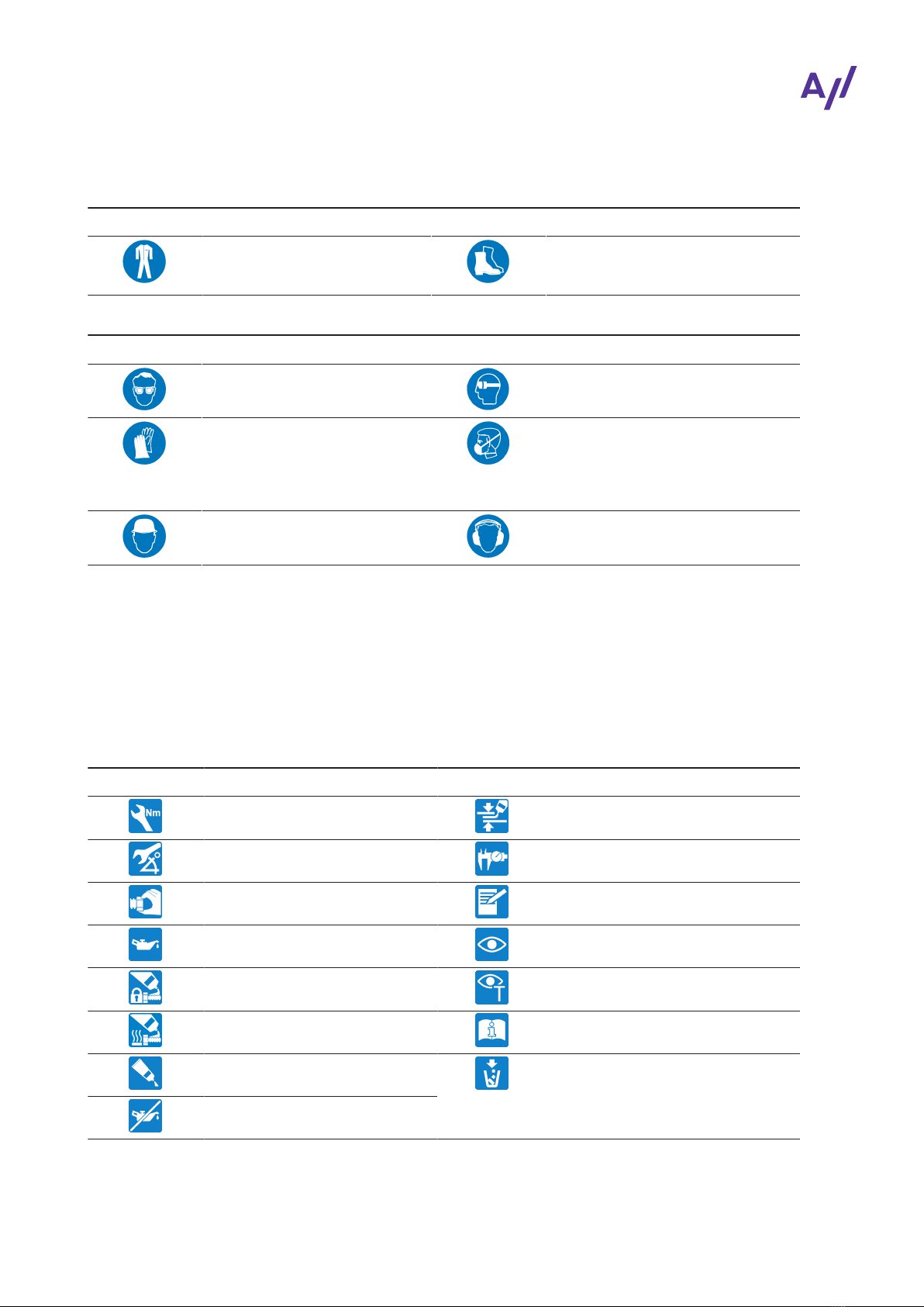
Wear safety footwear to protect against mechanical hazard and risk of falling.
Wear protective clothing.
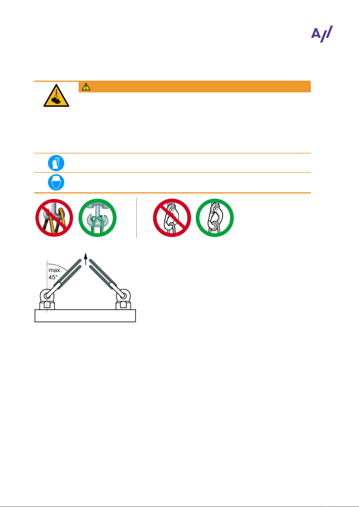
WARNING
Risk of falling
When working on the turbocharger, there is a risk of falling.
uDo not climb onto the turbocharger or onto attached parts and do not use them
as climbing aids.
uUse suitable climbing aids and working platforms for work above body height.
uOnly perform work on the turbocharger when you are in a physically and psychologically stable
condition.
uOnly work with suitable tools, equipment and appliances that function properly.
uKeep the workplace clean; clear away any loose objects and obstacles on the floor.
uKeep the floor, equipment, and turbocharger clean.
uHave oil binding agents ready and provide or keep oil pans at hand.
Welding work in the vicinity of the turbocharger
uWhen performing welding work in the vicinity of the turbocharger, always cover the filter silencer
to prevent the filter mat from being damaged.
uKeep flammable objects and substances out of the vicinity of flying sparks.
uCover all connections on the turbocharger so that no foreign objects can enter the turbocharger.
uWear personal protective equipment (PPE) for welding operations.
Page 7 / 17

Assembly Instructions / A136-H
2 Safety / 2.3 Occupational safety
© Copyright 2022 Accelleron Industries. All rights reserved. HZTL455311P0038_EN Rev. C May 2022
Mechanical hazards when working on the turbocharger
WARNING
Mechanical hazard
Severe injuries to personnel or fatal accidents can be caused by mechanical influ-
ences as a consequence of hazardous and inadequate operational procedures.
uObserve the general rules for occupational safety and prevention of accidents.
uEnsure workplace safety.
uOnly perform operations that are described in this chapter.
uOnly perform operations for which you have previously received instruction or
training.
Hazards due to operating materials and supplies
Operating materials and supplies can include: Oils, greases, coolants, cleaning agents and solvents,
acids or similar substances.
WARNING
Handling operating materials and supplies
Swallowing or inhaling vapours of operating materials and supplies or contact with
them may be harmful to health. Flammable and combustible operating materials
and supplies can catch fire or resulting vapours can lead to an explosion.
uDo not breathe in these substances and avoid contact with the skin.
uEnsure proper ventilation.
uObserve the information in the material safety data sheet for the operating ma-
terials and supplies.
uComply with local legislation.
Wear safety goggles.
Wear safety gloves to protect against mechanical hazards.
Wear a respiratory mask to protect against gases.
Page 8 / 17

Assembly Instructions / A136-H
3 Turbocharger weight and transportation /
© Copyright 2022 Accelleron Industries. All rights reserved. HZTL455311P0038_EN Rev. C May 2022
3 Turbocharger weight and
transportation
Lifting gear with a sufficient load limit must be used for removing, installing and transporting the tur-
bocharger. The weight specified below applies to the heaviest variant possible. Depending on the
specification, the weight specified on the rating plate may be lower than the standard value specified
here.
Swivel lifting eyes to be used
Two swivel lifting eyes are required for the safe lifting of loads, which are not supplied by
ABB Turbocharging.
Fig.3: Swivel lifting eyes
Product Thread M Length L
[mm]
Minimum load limit
[kg]
Quantity
A136-H M10 17 mm 450 kg 2
Table4: Swivel lifting eyes
Fig.4: Suspension of complete turbocharger unit
Product Weights [kg]
A136-H 340
Table5: Weight of turbocharger A136-H
Page 9 / 17

Assembly Instructions / A136-H
4 Installing the turbocharger / 4.1 Inserting gaskets into the bracket
© Copyright 2022 Accelleron Industries. All rights reserved. HZTL455311P0038_EN Rev. C May 2022
4 Installing the turbocharger
4.1 Inserting gaskets into the bracket
CAUTION
Inserting the gaskets
Gaskets that are forgotten, damaged or improperly inserted will lead to oil leaks.
uAlways use new gaskets and insert them carefully into the slot.
The oil is supplied(02) and drained(03) through the bracket (01).
The necessary sealing is provided by O-rings. The O-rings are not included in the Turbo Systems
scope of delivery.
Fig.5: Inserting gaskets into the bracket
01 Bracket 04 Slot for O-ring
02 Oil supply 05 O-rings
03 Oil drain 06 Pin (optional)
Pin(06) as installation safety device
Turbochargers can have an oil inlet either on their right or left side; the oil inlet position can be differ-
ent for the turbocharger fitted on the left and on the right engine bank.
A pin can be installed in every support as an installation safety device to prevent inadvertent incor-
rect fitting. This pin fits into the respective slot on the foot of the bearing casing. Instructions of the
enginebuilder must be observed.
Page 10 / 17

Assembly Instructions / A136-H
4 Installing the turbocharger / 4.2 Fitting threaded rods
© Copyright 2022 Accelleron Industries. All rights reserved. HZTL455311P0038_EN Rev. C May 2022
4.2 Fitting threaded rods
Fastening material, scope of delivery
The threaded rods and nuts required for attaching the turbocharger to the bracket are not included in
the ABB scope of delivery.
Requirements for the threaded rods
Fig.6: Requirements for threaded rods
Product Diameter
Threaded rod
[mm]
Material
DIN / ISO 898
(Part 1)
Thread length
L1[mm]
Free length over
bracket
L2 [mm]
A136-H Ø 20 / M20 10.9 / 12.9 ≥ 30 225
Table6: Requirements for threaded rods
Fig.7: Fitting threaded rods onto the bracket
1. Lightly oil the surfaces of the threaded rods(02) to be screwed in.
2. Screw the threaded rods into the bracket with the aid of locknuts(01).
3. Remove nuts(01) again.
Page 11 / 17

Assembly Instructions / A136-H
4 Installing the turbocharger / 4.3 Placing the turbocharger on the bracket
© Copyright 2022 Accelleron Industries. All rights reserved. HZTL455311P0038_EN Rev. C May 2022
4.3 Placing the turbocharger on the bracket
Fig.8: Placing the turbocharger on the bracket
A Standard nut
uMake sure that covers of the oil and water connections are removed.
1. Make sure that the O-rings(03) are undamaged and positioned correctly in the slots.
2. Attach the lifting gear to the swivel lifting eyes(S) and loop around the gas outlet casing.
3. Position the turbocharger on the bracket(04) and align it. If present, pay attention to the posi-
tioning pin(05) in the bracket.
Safeguard against wrong fitting (only for water-cooled bearing casings)
Depending on the bracket version(04), two positioning pins(05) can be used for positioning and
safeguarding against wrong fitting of the turbocharger. Therefore the turbocharger must always be
removed from and installed on the bracket vertically.
Page 12 / 17

Assembly Instructions / A136-H
4 Installing the turbocharger / 4.4 Fastening the turbocharger with a standard nut
© Copyright 2022 Accelleron Industries. All rights reserved. HZTL455311P0038_EN Rev. C May 2022
4.4 Fastening the turbocharger with a standard nut
uFit the nuts and tighten them according to variant 1 or 2 in the table below.
Product Through hole in
bearing casing [mm]
Fixing screws [mm] Variant 1: Tightening
torques [Nm] **)
Variant 2: Hydraulic
pre-tensioning
forces [kN]
A136-H Ø 21 M20 560 175
Table7: Tightening torque for standard nuts
**) When the turbocharger is mounted on the engine support, the bolt threads and screw heads must
be lightly oiled (assumed friction coefficient µ = 0.12 for tightening torque)
uRemove the lifting gear.
4.5 Connecting the turbocharger
uConnect the cable to the speed sensor(86515).
uConnect all exhaust gas, water, blow-by and air lines according to the instructions of the engineb-
uilder.
Version with compressor wheel cooling
CAUTION
Failure of compressor wheel cooling
Any prolonged failure of the compressor wheel cooling will shorten the replacement
interval of the compressor wheel.
uMake sure there is an uninterrupted supply of cooling air during operation.
Fig.9: Connecting the compressor cooling air intake
uRemove the lock from the connection for the compressor wheel cooling (01) and fit the cooling air
line.
Page 13 / 17

Assembly Instructions / A136-H
5 Storage of new turbochargers and spare parts /
© Copyright 2022 Accelleron Industries. All rights reserved. HZTL455311P0038_EN Rev. C May 2022
5 Storage of new turbochargers and
spare parts
Storage of new turbochargers and spare parts for up to 6 months
New turbochargers and spare parts can be stored in their closed packages for 6months from the
date of delivery without additional mothballing measures.
Only dry rooms in which the relative humidity is between 40…70% and no condensation can form are
suitable for storage.
Storage of new turbochargers and spare parts for more than 6 months
As the contents of the package are adapted as required, turbochargers may also be delivered
without a VCI label.
For parts with a VCI label on the package, the following instructions must be observed.
Fig.10: Volatile Corrosion Inhibitor (VCI)
WARNING
Health protection when handling VCI
VCI products are not hazardous in terms of the Ordinance on Hazardous Sub-
stances. Nevertheless, the following points must be observed when handling VCI:
uObserve information in material safety data sheet
uEnsure proper space ventilation.
uDo not eat, drink or store food at the workplace while working with VCI.
uClean hands and face after working with VCI.
uFor more information, see www.branopac.com.
Wear safety gloves to protect against mechanical hazards.
Every 6months, the following mothballing measures are required:
uOpen package.
uRemove VCI corrosion protection emitter from package and replace with a new VCI corrosion pro-
tection emitter of the same kind. New VCI corrosion protection emitters can be obtained from
www.branopac.com.
uOld VCI corrosion protection emitters must be disposed of in an environmentally compatible, pro-
fessional way and in compliance with locally applicable regulations.
uSeal the package. The more tightly the package is sealed, the longer the protection will last.
Page 14 / 17

Assembly Instructions / A136-H
5 Storage of new turbochargers and spare parts /
© Copyright 2022 Accelleron Industries. All rights reserved. HZTL455311P0038_EN Rev. C May 2022
Long-term storage of turbochargers
The turbochargers will be prepared for long-term storage if requested in the purchase order. The
package is equipped with a hygrometer (see illustration).
Fig.11: Package with hygrometer
Every 6months, the following measures are required:
uCheck the hygrometer(02) in the sight-glass. There is an opening(01) in the wooden crate which
allows this check to be carried out. When the display field has changed colour at the 70% level,
the maximum permissible humidity has been exceeded. In this case, the turbocharger must be in-
spected by a Accelleron service station and repacked.
uInspect the package for damage. If the package is damaged, the turbocharger must be inspected
by a Accelleron service station and repacked.
After every 3 years the following work steps must be performed by a Accelleron service station:
¡Inspect the component
¡Replace the desiccant agent
¡Repackage the component.
NOTICE
70% field of the hygrometer has not changed colour
If the 70% field of the hygrometer(02) has not changed colour and the package is
undamaged, the turbocharger can be put into operation without any prior inspec-
tion by a Accelleron service station.
Unpacking the turbochargers
The corrosion protection effect ends after the material is unpacked from the VCI package.
To avoid the formation of condensation, the surroundings and the content of the package must have
the same temperature during unpacking.
Page 15 / 17

Assembly Instructions / A136-H
5 Storage of new turbochargers and spare parts /
© Copyright 2022 Accelleron Industries. All rights reserved. HZTL455311P0038_EN Rev. C May 2022
Page 16 / 17

Assembly Instructions / A136-H
6 Further information /
© Copyright 2022 Accelleron Industries. All rights reserved. HZTL455311P0038_EN Rev. C May 2022
6 Further information
The Operation Manual must be observed with regard to commissioning, operation, maintenance and
ordering spare parts.
NOTICE
Operation Manual
The Operation Manual for the turbocharger with the relevant serial number is avail-
able online on our website www.accelleron-industries.com.
Fig.12: Serial number of the turbocharger on the rating plate
One rating plate (01) each is attached on the left and the right side of the turbocharger bearing cas-
ing.
1. Read the serial number(02) on the rating plate(01) of the turbocharger.
uThe Operation Manual can be found online in accordance with the details on the following page.
Page 17 / 17

Contact information
Further information
Find your nearest Service Station on the website.
Find and download the Operation Manual of your product on the website
(see “Operation Manuals“).
Accelleron Industries Ltd
Bruggerstrasse 71a
5400 Baden, Switzerland
+41 58 585 7777
accelleron-industries.com
Visit our website by scanning the QR code.
© Copyright 2022 Accelleron Industries. All rights reserved.
Table of contents
Other Accelleron Batteries Charger manuals
Popular Batteries Charger manuals by other brands

Universal Power Group
Universal Power Group XPAL Ivy II Specifications

Solar Electronics
Solar Electronics Fronius Symo Installation

RCA
RCA WP4UAR Guía del usuario

Associated Equipment
Associated Equipment ESS6011 Operator's manual

Defort
Defort DBC-6D user manual

efacec
efacec EFAPOWER EV-QC45 Installation and user manual