ACCO Brands GBC Sharp SmartPunch Pro User manual

Sharp SmartPunch Pro Installation Manual 1
Sharp SmartPunch™Pro
Installation Manual
ACCO Brands, Inc.
Four Corporate Drive
Lake Zurich, IL 60047
www.acco.com

Sharp SmartPunch Pro Installation Manual 2
Contents Page
1. Recommendations and Pre-requisites 3
2. Unpacking 3
3. Cable Connections 3
4. Installing the Sound Deadening Foam 6
5. Docking Bracket Installation 8
6. Leveling & Height Adjustment 9
7. Final Steps 10

Sharp SmartPunch Pro Installation Manual 3
1 Recommendations and Pre-requisites
•You will need the installation kit provided with the SmartPunch Pro unit, which can be found in the
main carton.
2 Unpacking
•Inspect the outside of the package for shipping damage. If there is evidence of shipping damage,
contact the shipping carrier immediately.
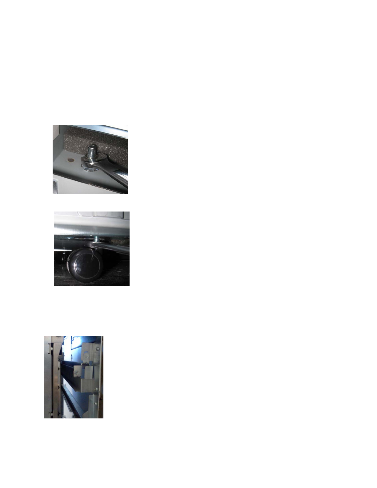
•Remove the punch from its shipping carton. Three people are recommended, one lifting at the
casters while two lift at the top cover. DO NOT lift using the front door panel.
•Retain the smaller accessory box; it contains parts required for correct installation of the
SmartPunch Pro. See below for content details.
•Inspect for any concealed damage to the unit. If there is evidence of concealed shipping damage,
contact the shipping carrier immediately.
•Remove all shipping tape from doors and levers.
Installation Kit Contents
Item Description Qty
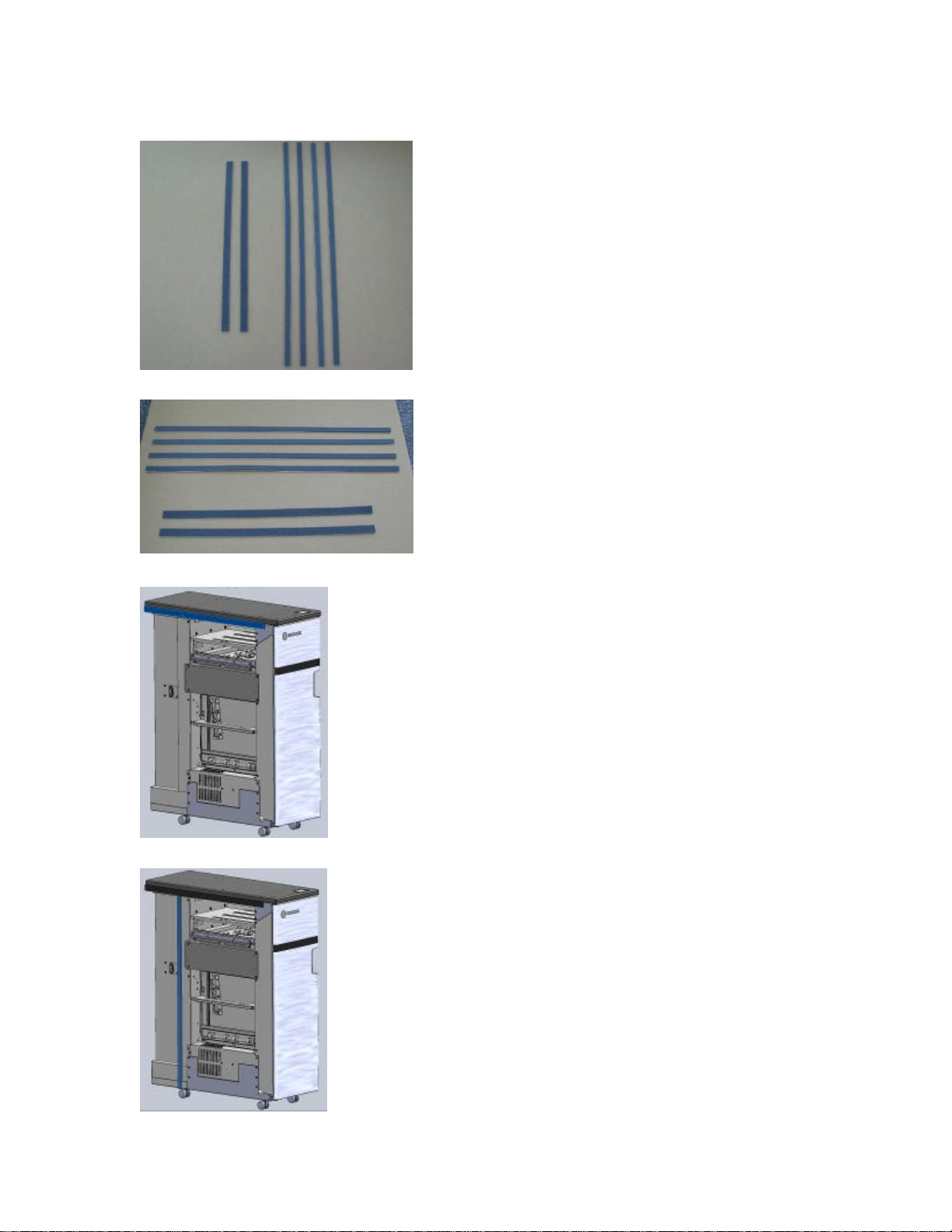
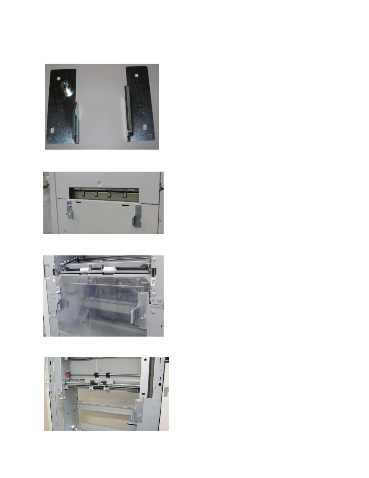
1 Long Entrance Guide 1
2 Short Entrance guide 1
3 Communication Cable Assembly 1
4 Installation Manual 1
5 Soundfoam Gasket Type 1 2
6 Soundfoam Gasket Type 2 4
7 Cable tie15
8 Power Cord21
9 User Manual 1
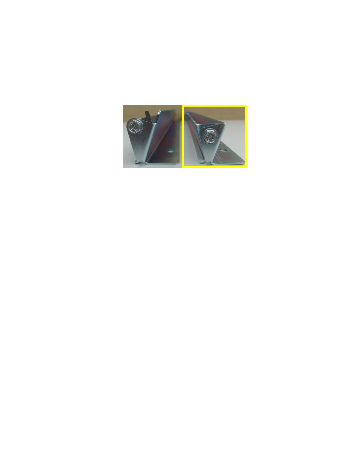
10 Left Docking Bracket 1
11 Right Docking Bracket 1
12 M4x10mm Long Thread Forming Screw 4
13 Hex Head #8-32 Machine Screw 4
1Item image not shown
2Item may differ from image shown for other countries
12
34
6
5
9
8
10 11 12 13
Includes 2 x M4x6 long screws for assembly

Sharp SmartPunch Pro Installation Manual 4
3 Cable Connections and Paper guides
Review the table below to identify which section of the guide to refer to install the SmartPunch Pro
Section Device upstream to SmartPunch Pro
3.1 MX-CF11 Inserter (or) MX-ST10 High Capacity Stacker
3.2 MX-RB18 Curl correction unit
3.1 Cable connections
a) i) Remove the finisher rear cover and plug the 7 pin communication cable to CN145 on the
finisher board. The communication cable, Item 3, is provided in the Installation kit of SmartPunch
Pro. (Finisher to SmartPunch Pro cable P/N OPT7712585)
a)ii) Attach the bracket tied to the communication cable with the 2 M4x6mm long screws provided
with the communication assembly.

Sharp SmartPunch Pro Installation Manual 5
a)iii) Plug the free end of the cable from step a) into the right side of the SmartPunch Pro.
b) Plug the appropriate power cord into the side of the machine next to the communication
connector. The exact location can be seen in the above picture. Insert the plug into the power supply
socket.
c)i) There are two entrance paper guides provided with the SmartPunch Pro. Use the longer paper
guide measuring about 31mm (in paper flow direction) when used in conjunction with Inserter MX-
CF11 or High Capacity Stacker MX-ST10. When connecting to the MX-CF11 follow the procedure in
d) below before installing the paper guide. Otherwise, install the paper guide, using the size #8
screws provided, to the lower entrance guide of the SmartPunch Pro.
Long guide Short guide
Go to Section 4 to complete the installation.
d)i) Remove the screws from both ends.
d)ii) Attach the black Mylar from the MX-CF11 parts kit to the lower bracket at the reference edge
shown in the image. Once complete re-assembly the bracket for installation.
Before
After

Sharp SmartPunch Pro Installation Manual 6
Go to Section 4 to complete the installation.
3.2 Cable connections
Follow the same steps as in 3.1 a, b.
c) There are two entrance paper guides provided with the SmartPunch Pro. Use the shorter paper
guide measuring about 24mm (in paper flow direction) when used in conjunction with Curl correction
unit MX-RB18. Install the paper guide, using the size #8 screws provided, to the lower entrance guide
of the SmartPunch Pro.
Long guide Short guide
Go to Section 4 to complete the installation.

Sharp SmartPunch Pro Installation Manual 7
4. Installing the Sound Deadening Foam
Supplied with the SmartPunch Pro, you will find six
strips of sound deadening foam that are shipped
loose for field installation. These are not attached
at the factory to avoid compression and/or damage
during shipping.
To install, simply peal the back off to reveal the
adhesive using the following steps as a reference.
4.1 Paper Exit Side (Finisher Side)
Apply one of the two shorter strips to the Top
cover. Align it so that
a. the short edge of the foam lines up
with the rear edge of the Top cover
and
b. the long edge of the foam lines up
with the bottom edge of the Top
cover.
Apply one of the four longer strips to the side
of the rear cover. Align it so that:
a. the long edge of the foam lines up
with the edge of the rear cover and
b. the short edge of the foam touches
the horizontal sound foam in the top.

Sharp SmartPunch Pro Installation Manual 8
Apply another longer strip to the side cover.
Align it so that the long edge of the foam is in
line with the end of the horizontal foam.
Exit side complete
4.2 Paper Entrance Side (Main Unit Side)
Apply the remaining short strip to the Top cover.
Align it so that
a. the short edge of the foam lines up with
the rear edge of the Top cover and b.
b. the long edge of the foam lines up with
the bottom edge of the Top cover.
Apply one of the two remaining long strips to the
side of the rear cover. Align it so that:
a. the long edge of the foam lines up with
the edge of the rear cover and
b. the short edge of the foam touches the
horizontal sound foam in the top.
Apply the last remaining long strip to the left side
of the main unit side of the SmartPunch Pro along
the flange of the front frame touching the
horizontal foam on the top.

Sharp SmartPunch Pro Installation Manual 9
5. Docking Bracket Installation
MX-ST10 High Capacity Stacker
The docking brackets are shipped in a
separate bag along with size M4x10
mounting screws (not shown).
MX-RB18 Curl Correction Unit
MX-CF11 Inserter
Install as shown with the bracket
marked “R” on the right side facing
you as you look at the exit side of the
upstream device (pictures shown).
Install the bracket marked “L” on the
left side facing you. Both brackets
should be oriented with the arrow
facing up.
The docking bracket(s) provided with the
finisher should be attached to the
downstream side of the SmartPunch Pro
with (4) M4x10 size screws.

Sharp SmartPunch Pro Installation Manual 10
6. Leveling & Height Adjustment
6.1 Height Setting
No height adjustment of the SmartPunch Pro is required, for an installation site with a level floor. If the
floor is uneven then it is recommended to set the level of the SmartPunch Pro using the upstream device
as a reference.
6.2 Adjusting the Casters
a)
Using a 9/16” (15mm) open ended wrench, loosen
the jam nut(s) situated on the caster stud inside of
the machine.
b)
Using the 9/16” (15mm) wrench, rotate the caster
stems to change the height.
Re-tighten the jam nuts once the correct height is
achieved.
6.3 Fixing the Lock Lever
Once the SmartPunch Pro has been leveled and the correct height set, push it so the front and rear
frames are outside the docking brackets. Push the lock lever in and use an #8-32 to secure in place.

Sharp SmartPunch Pro Installation Manual 11
7. Final Steps
7.1 Main Unit & Finisher Firmware
Confirm that the main unit and finisher have the latest firmware installed. Firmware can be obtained by
contacting Sharp service.
7.2 Setting the Dip Switch
SmartPunch Pro unit is fitted with a dip-switch and the setting should be changed depending on the main
unit it is attached to. The dip-switch is located next to the firmware upload connector on the rear cover.
Set the dip-switch per the table below.
Dip Switch Setting
Main Unit 1
2
3
45678
MX-M904, MX-M1054, MX-M1204 OFF OFF OFF OFF ON ON ON ON
MX-7500N, MX-6500N ON ON ON ON OFF OFF OFF OFF
7.3 Enabling the Punch Icon
The power switch for the SmartPunch Pro can be found on the front frame on the
lower left corner (shown left). Turn the SmartPunch Pro on before the main unit.
The Punch icon (shown right) will appear automatically if
the connections are made correctly and the power is
cycled.
7.4 Functional Test
Functional test the SmartPunch Pro system
a) Check to ensure that the paper chip tray is securely in place.
b) Check to ensure that a die set is installed properly and that any extra die sets are securely stored in
the die storage area. The die is inserted as shown and should be pushed smoothly and firmly until it clicks
into place.
Inserting the die Die storage area
c) Run a small test job in “Bypass” mode. Check to ensure that the job is not punched and bypasses
properly.
d) Run a small job with punch enabled. Check the punched holes of the job.
e) Run each die set to punch 100 sheets or until there is no oil residue around the holes.
Table of contents
Other ACCO Brands Office Equipment manuals