Salda VEKA 350 EC Guide

VEKA 350 EC
EN MOUNTING AND INSTALLATION INSTRUCTION

2 | EN VEKA 350 EC v2019.06
CONTENT
2.SYMBOLS AND MARKING 3
3.SAFETY INSTRUCTIONS AND PRECAUTIONS 3
4. DIMENSIONS 4
5.ELECTRICAL DATA 4
6.TRANSPORTATION 5
7. DESCRIPTION 5
8.SAFETY PRECAUTIONS 6
9. MOUNTING 6
10.CONNECTION OF THE AIR DUCT 7
11.CONNECTION DIAGRAM 7
12.CONNECTION OF THE UNIT TO ELECTRIC NETWORK 7
12.1. SYSTEM PROTECTION 8
12.2.RECOMMENDATIONS BEFORE THE START OF THE UNIT (BEFORE THE FINAL USER) 8
12.3.POSSIBLE FAULTS AND TROUBLESHOOTING 8
13.MAINTENANCE 8
13.1. FILTERS 8
13.2. FAN 9
13.3. ELECTRICAL HEATER 9
14.ELECTRICAL CONNECTION DIAGRAM 10
15.ECODESIGN DATA TABLE 12
16.DECLARATION OF CONFIMITY 13
17. WARRANTY 14
17.1. LIMITED WARRANTY COUPON 14

EN | 3VEKA 350 EC v2019.06
2. SYMBOLS AND MARKING
LN: XX000000
2019.01.01
Figure. 2.1. Technical label
1 - Logo; 2 - Product code (SKU); 3 - Product name; 4 - Technical data; 5 - Production place; 6 - Lot number and production date; 7 - Serial
number.
SERIAL
2514523357
XXXGAMINIOPAVADINIMAS
Nominalvoltagefrequency
Max.current
Max.powerconsumption
Protectionclass
Weight
/ xxx/xxVAC/Hz
x.xxA
x.xxkW
IPxx
xxkg
MadeinŠiauliai, Lithuania
AHU000000
BN:xxxxxx
2019/01/01
SERIAL
2514523357
XXXGAMINIOPAVADINIMAS
Nominalvoltagefrequency
Max.current
Max.powerconsumption
Protectionclass
Weight
/xxx/xxVAC/Hz
x.xxA
x.xxkW
IPxx
xxkg
MadeinŠiauliai, Lithuania
AHU000000
BN:xxxxxx
2019/01/01
SERIAL
2514523357
XXXGAMINIOPAVADINIMAS
Nominalvoltagefrequency
Max.current
Max.powerconsumption
Protectionclass
Weight
/ xxx/xxVAC/Hz
x.xxA
x.xxkW
IPxx
xxkg
MadeinŠiauliai, Lithuania
AHU000000
BN:xxxxxx
2019/01/01
SERIAL
2514523357
XXXGAMINIOPAVA DINIMAS
Nominalvoltagefrequency
Max.current
Max.powerconsumption
Protectionclass
Weight
/ xxx/xxVAC/Hz
x.xxA
x.xxkW
IPxx
xxkg
MadeinŠiauliai, Lithuania
AHU000000
BN:xxxxxx
2019/01/01
SERIAL
2514523357
XXX GAMINIO PAVADINIMAS
Nominal voltage frequency
Max.current
Max.power consumption
Protection class
Weight
/ xxx/xx VAC/Hz
x.xx A
x.xx kW
IP xx
xx kg
Made in Šiauliai, Lithuania
AHU000000
BN:xxxxxx
2019/01/01
SERIAL
2514523357
XXX GAMINIO PAVADINIMAS
Nominal voltage frequency
Max.current
Max.power consumption
Protection class
Weight
/ xxx/xx VAC/Hz
x.xx A
x.xx kW
IP xx
xx kg
Made in Šiauliai, Lithuania
AHU000000
BN:xxxxxx
2019/01/01
SERIAL
2514523357
XXX GAMINIO PAVADINIMAS
Nominal voltage frequency
Max.current
Max.power consumption
Protection class
Weight
/ xxx/xx VAC/Hz
x.xx A
x.xx kW
IP xx
xx kg
Made in Šiauliai, Lithuania
AHU000000
BN:xxxxxx
2019/01/01
SERIAL
2514523357
XXX GAMINIO PAVADINIMAS
Nominal voltage frequency
Max.current
Max.power consumption
Protection class
Weight
/ xxx/xx VAC/Hz
x.xx A
x.xx kW
IP xx
xx kg
Made in Šiauliai, Lithuania
AHU000000
BN:xxxxxx
2019/01/01
Figure. 2.2. Technical label place
Figure. 2.3. Indication for duct connection.
ODA - outdoor air; SUP - supply air.
3. SAFETY INSTRUCTIONS AND PRECAUTIONS
Read this instruction very carefully before installing and using this equipment. Installation, connection and maintenance should be carried out by
a qualifed technician and in accordance with the local rules and legal acts.
The company shall take no responsibility for the injuries suered by the people or for the damaged property, if the safety requirements are not
followed or the device is modifed without the permission of the manufacturer.
Warning – pay attention Additional information
Main safety rules
Danger
• Before performing any electricity or maintenance tasks make sure, that the device is disconnected from the mains, that all moving parts
of the device have stopped.
• Make sure that the fans can not be entered through air ducts or branch openings.
• If you notice liquids on electric parts or connections that bear voltage, stop the operation of the appliance.
• Do not plug the device into the mains, that diers from the one indicated on the label or on the housing.
• Voltage of the mains should comply with the electrotechnical parameters indicated on the label.
• The device should be earthed in accordance with the rules of installation of electric appliances. It is forbidden to turn on and use un-
earthed device. Follow the requirements of the device’s labels that indicate Danger.

4 | EN VEKA 350 EC v2019.06
Warnings
• Connection of electricity and maintenance of the device should be performed only by a qualied personnel, in accordance with the
manufacturer’s instructions and valid safety requirements.
• In order to reduce the risk during installation and maintenance, suitable protective clothes should be worn.
• Beware of sharp angles while performing installation and maintenance tasks.
• Do not touch heating elements until they haven’t cooled down.
• Some devices are heavy, thus one should be very careful while transporting and installing. Use suitable lifting equipment.
• While connecting electricity to the mains a circuit breaker of suitable size is necessary.
Warning!
• If the device is installed in a cold environment, make sure that all connections and tubes are properly isolated. Intake and discharge air
ducts should be isolated in all cases.
• Openings of the ducts should be covered during transportation and installation.
• Make sure not to damage the heater when connecting the piping of the water heater. For tightening up, use a wrench/spanner.
Before starting the equipment
• make sure, that there are no strange objects inside;
• manually check whether fans are not stuck or blocked;
• if rotary heat exchanger is installed in the device, make sure that it is not stuck or blocked;
• check the grounding;
• make sure that all components and accessories are connected in accordance with the project or provided instructions.
Danger: Fumes
Salda Antifrost system uses dis-balancing of the air ow and it may cause negative pressure in premises. Great care should be taken
when using at the same time in premises as another heating appliance what depend on the air in premises. Such appliances include
gas, oil, wood or coal-red boilers and heaters, replaces, continuous ow or other water heaters, gas hobs, cookers or ovens which
draw air in from the room and duct exhaust gases out through a chimney or extraction ducting. The heating appliance can be starved
of oxygen, impairing combustion. In exceptional cases harmful gases could be drawn out of the chimney or extraction ducting back
into the room. In this case we strictly recommend to turn o Salda Antifrost and use an external preheater for heat exchanger anti-frost
protection (see Salda Antifrost function on the Remote controller manual).
4. DIMENSIONS
850
790
125
200
206
650
330
302
260
D
E
F
C
1
2
3
4
B
A
3
2
1
5
C
D
4
6
7
8
A
B
A3
Lapas 6 is 8
Mastelis:1:5
Detallės/mazgo kodas
Detalės/mazgo pavadinimas
Revizija
Nekeisti brėžinio mastelio
Medžiaga:
Data
Parašas
V.Pavardė
TE
VK
Braižė
N. Kisielis
2014-06-19
Gaminio pavadinimas
Svoris:
Tolerancijos pagal ISO 2768-m
Ilgio(mm)
0,5-3
3-6
6-30
30-120
120-400 400-1000
1000-
2000
2000-
4000
±0,1 ±0,1 ±0,2 ±0,3 ±0,8 ±1,2
±2
±0,5
g
VEKA 350 EC
G.Taujenis
S= mm
Lenkimo r=mm
Plotas S= m2
BraižėBraižė
Įteisinimas
5. ELECTRICAL DATA
VEKA EC 2.2/3.2 1f VEKA EC 3.0/4.5 2f
Heizregister
- phase/voltage [50 Hz/VAC] ~1, 230 ~2, 400
- power/current [kW/A] 2,2 / 9,56 3,2 / 13,91 3,0 / 7,54 4,5 / 11,3
- min. airspeed [m/s] 1,5
Cross-section of the power supply cable [mm²] 3x1,5 3x2,5 4x1,5
Circuit breaker Poles 1 2
I [A] B16 B16 B10 B16

EN | 5VEKA 350 EC v2019.06
Fan
- phase/voltage [50 Hz/VAC] ~1, 230
- power/current [kW/A] 0,056 / 0,46
- speed [min-1] 4385
- protection class IP-44
Cross-section of the power supply cable [mm²] 3x1,0
Circuit breaker Poles 1
I [A] B2
min. ambient temperature [ °C ] -25
max. ambient temperature [ °C ] 60
6. TRANSPORTATION
Units are packed in the factory to comply needs of normal transportation handling. Use suitable lifting and moving equipment when handling units
in order to prevent damages and injuries. Do not use cables, terminal boxes, and inlet-exhaust anges for lifting and moving units. Avoid hits and
shock loads. Units should be stored in dry rooms where relative humidity max. 70% (at +20°C), ambient temperature is within the range of +5°C
to +40°C. Units should be protected from dust, dirt and water.
Avoid long term storaging. Longer than 1 year is not recommended.
Figure. 6.1. Lifting with forklift.
Only a product placed on a pallet may be lifted in order to prevent damage to the casing.
7. DESCRIPTION
Highly eective super-compact air supply unit for ventilating and heating rooms. It is a perfect solution for low height installations – bars, restau-
rants, oces, shops, apartments and sports facilities.
Super-compact size h/w/l 200x260x790
Max airow 350m3/h
Motor power consumption less than 55W
Powder painted white color RAL 9016
Housing insulation, mineral wool 20mm
You can choose 2 types of electric heaters.
Each heater‘s power can be switched depending on the heater model.
G4 panel lter
Easy and quick installation
Simple maintenance
Optional electrical heater Air supply unit VEKA 350 EC has an option for 2 types electrical heaters:
VEKA 2.2/3,2-1single-phase\VEKA 350 – one phase heater, with an option to set power 2,2kW or 3,2kW.

6 | EN VEKA 350 EC v2019.06
VEKA 3.0/4,5-2two-phase\VEKA 350 – two phase heater, with an option to set power 3,0 kW or 4,5kW.
Standard package consists of:
Air supply unit VEKA 350 EC
Electric heater*
Mounting parts
Legs - 4 pieces .
Screws - 10 pieces .
* - ordered, supplied separately. Client is responsible for installation and connection.
8. SAFETY PRECAUTIONS
- Do not use the unit for purposes other than its’ intended use.
- Do not disassemble or modify the unit in any way. Doing so may lead to mechanical failure or injury.
- Use special clothing and be careful while performing maintenance, and repair jobs - edges of the components’ casings may be sharp and cutting.
- Do not wear loose clothing that could be pulled in to operating unit.
- Do not place ngers or other foreign objects through inlet or exhaust guards or into connected duct. Should a foreign object enter the unit,
immediatelly disconnect power source. Be certain all mechanical motion has stopped, the heater cooled down, and make sure that restart is not
possible before removing foreign object.
- Do not connect to any other power voltage source than indicated on the product label.
- Use external motor protection-switcher only corresponding to the nominal current specication on the model label.
- - Inlet power cable must be selected according to the overall capacity of the unit and operation conditions.
- Never use the cable if the insulation is damaged and if there are any visual defects.
- Do not use power cable with frayed, cut, or brittle insulation.
- Never handle energized power cable with wet hands.
- Never let power cables or plug connections lay in water.
- Do not place or operate unit on unsteady surfaces and mounting frames.
- Mount the unit rmly to ensure safe operating.
- Never use this unit in any explosive or aggressive elements containing environment.
9. MOUNTING
- Installing should only be performed by qualied and trained sta.
It is recommended to x the AHU using auxiliary proles.
- Mount the unit on safe and rm base.
- Connecting the duct system refer to air ow labels.
Notice: Mounting parts are included into standard package:
1. Screw M5x16 DIN 7985;
2. Spring washer 5 DIN 127;
3. Washer 5 DIN 440R;
4. Anti-vibration tread;
5. Hanging bracket.
180o
Figure. 9.1. Mounting positions

EN | 7VEKA 350 EC v2019.06
Figure. 9.2. under the ceiling installation
10.CONNECTION OF THE AIR DUCT
Figure. 10.1. Circular air duct conection
D2 dimensions depend on unit.
11.CONNECTION DIAGRAM
Figure. 11.1. Indication for duct connection.
ODA - outdoor air; SUP - supply air.
PV - supply air fan
KE - electrical heater
PF - lter for supply air
* Additional purge function
12.CONNECTION OF THE UNIT TO ELECTRIC NETWORK
• Supply voltage to the unit must be connected by a qualied specialist following the manufacturer’s instructions and eective safety instructions.
• The unit’s power network voltage must correspond to electrotechnical parameters of the unit indicated in the technical decal.
• The unit’s voltage, power and other technical parameters are provided in the unit’s technical decal (on the unit casing). The unit must be connect-
ed to the voltage plug socket of the grounded power network in compliance with the eective requirements.
• The unit must be earthed according to the rules on installing electrical equipment.
• It is prohibited to use extension wires (cables) and power network plug socket distribution devices.
• Prior to carrying out any ventilation unit installation and connection activities (until its hand-over to the customer), the unit must be disconnected
from the power network.
• After installation of the ventilation unit, the power network plug socket must be accessible at any time and disconnection from the power network
is performed through the two-pole circuit breaker (by disconnecting phase pole and neutral).
• The unit must be thoroughly checked against damages (execution, control, measurement nodes) during transportation before it is connected to
the power network.
• The power cable can be replaced only by a qualied specialist upon the evaluation of the rated power and current.
The manufacturer does not assume any liability for personal injuries and property damage due to nonconformance with the
provided instructions.

8 | EN VEKA 350 EC v2019.06
12.1. SYSTEM PROTECTION
Do not use this unit for purposes other than those provided in its design.
Do not dismantle and modify the unit. Such actions can cause mechanical fault or even injury.
Use special working clothes when installing and maintaining the unit. Be careful – angles and edges of the unit and its components can be sharp
and cause injuries.
Being near the unit, do not wear free streaming clothes that could be sucked into the operating fan.
All products packed in the factory are not prepared for eventual operation. The units can be used only by connecting them to air ducts or by install-
ing protection grating in air intake and discharge openings.
Do not put ngers or any other objects into protection grating of air intake and discharge or into connected air duct. In case any foreign body get
into the unit, disconnect the power supply source immediately. Before removal of foreign body, make sure that any mechanical movement in the
unit has stopped. In addition, make sure that the accidental switching-on of the unit is impossible.
Avoid direct contact with the ow of supplied and extracted air.
Do not connect the unit to the mains other than indicated in the manufacturer’s label on the casing of the unit.
Never use a damaged power supply cable.
Never touch with wet hands the power supply cables connected to the mains.
Never dip extension cords and plugs in water.
Do not install and use the unit on uneven surfaces or other unstable planes.
Never use this unit in the environment conducive to explosion and containing any aggressive materials.
12.2. RECOMMENDATIONS BEFORE THE START OF THE UNIT (BEFORE THE FINAL USER)
Prior to start-up the system must be thoroughly cleaned. Check whether:
• operation systems and unit elements as well as automation and automation devices were not damaged during installation,
• all electrical devices are connected to power supply and t for service,
• all necessary automation elements are installed and connected to power supply and terminal blocks,
• cable connection to terminal blocks comply with the existing power connection diagrams,
• all electrical equipment protection elements are properly connected (if they are additionally used),
• cables and wires correspond to all applicable safety and functional requirements, diameters, etc.,
• earthing and protection systems are properly installed,
• condition of all seals and sealing surfaces are proper.
12.3. POSSIBLE FAULTS AND TROUBLESHOOTING
FAILURE CAUSE EXPLANATION / CORRECTIVE ACTIONS
Unit is not operating
No supply voltage Check whether the device is connected to the
power network
Protection device is o or a current
leakage relay is active (if installed by the
installer)
Switch on only if the unit condition has been
evaluated by a qualied electrician. If the sys-
tem failed, the failure MUST BE rectied prior
to switching it on.
Air supply heater or pre-heater is not operat-
ing or malfunctioning (if installed)
Too low air ow in air ducts activates auto-
matic
protection
Check if air lters are not clogged
Check if fans are rotating
Manual protection is activated
Possible heater or unit failure. MUST contact
the servicing sta for failure detection and its
elimination.
Too low air ow at rated fan speed Clogged supply and/or extract air lter(s) Filter replacement needed
Filters are clogged and no message is shown
on the remote control
Wrong time in lter timers or their switch is
broken, or its pressure is set improperly.
Shorten lter timer time till the message of
clogged lters or replace the pressure switch
of the lters, or set their proper pressure.
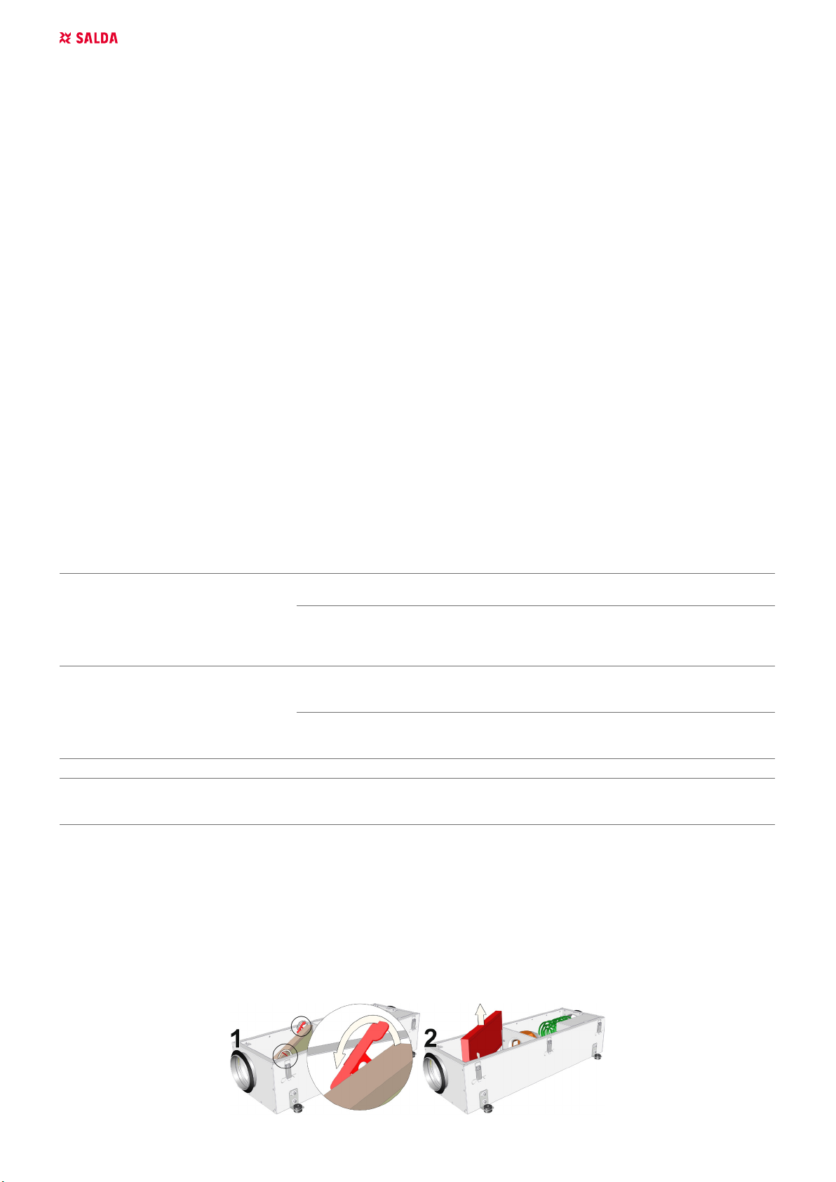
13.MAINTENANCE
Unplug unit from mains rst and wait for 2 minutes (till fan fully stops) before opening the covers.
13.1. FILTERS
Dirty lters increase air resistance in the lter, i.e. less air volume is supplied into the premises.
- Filter preferably should be exchanged with a new one every 3 months.

EN | 9VEKA 350 EC v2019.06
13.2. FAN
- Maintenance and repair should only be performed by experienced and trained sta.
- The fan should be inspected and cleaned at least once a year.
- Be sure the fan is disconnected from power source before performing any maintenance or repair.
- Proceed to maintenance and repair after any rotation in the fan stopped.
- Observe sta safety regulations during maintenance and repair.
- The motor is of heavy duty ball bearing construction. The motor is completely sealed and requires no lubrication during its lifetime.
- Detach fan from the unit.
- Impeller should be specially checked for buil-up material or dirt which may cause an imbalance. Excessive imbalance can lead to accelerated
wear on motor bearings and vibration.
- Clean impeller and inside housing with mild detergent, water and damp, soft cloth.
- Do not use high pressure cleaner, abrasives, sharp instruments or caustic solvents that may scratch or damage housing and impeller.
- Do not plunge impeller into any uid.
- Make sure the impeller is not hindered.
- Mount the fan back into the unit. Connect the fan to power supply source.
- If the fan does not start after maintenance or repair, contact the manufacturer.
13.3. ELECTRICAL HEATER
Electrical heaters do not require additional servicing. Change the air lter in time, as described above.
The heater has 2 thermal protections: automatic restore which is activated at +50°C and manual restore which is activated at +100°C.
If the manual restore protection is activated, disconnect the unit from the power supply source. Wait until the heating elements cool down and the
fan rotation stops. Press the Reset button and start the unit.
The electric heater can be removed if necessary. Disconnect the electric connector from the heater and pull out the heater.
123
4
5
Disconnect all power and control cables (if used)
Heater‘s power change is provided in the wiring diagrams.

10 | EN VEKA 350 EC v2019.06
14.ELECTRICAL CONNECTION DIAGRAM
99
99
103
104
102
105
92
108
94
+KE1
100
101
98 97
106 106
90, 92
90, 91
91
93, 94
93
96 96
1
45, 46
45
44, 46
50
50
39
40
38
41
42
+KE1
28
29
2
44
2
35
43
47 47
42, 43
49 49 48 48
1
+10V
Tacho
GND
0-10V/PWM
1
2
3
4
5
6
-F-X3
7
8
794941-1
-M1
0,043kW
4480 min-1
PE
N
L
+10V
Tacho
GND
0-10V/PWM
yellow
red
white
green/yellow
blue
blue
braun
-RT1
1
2
-AT1
1
2
1
2
3
4
5
6
-M-X3
7
8
794821-1
PE
-J1
EK1,EK2,EK3 - heating element;
AT1 - automatic reset thermostat supply air heater;
RT1 - manual reset thermostat supply air heater;
M-X3 - male connector 8k;
F-X3 - female connector 8k;
X1,X2 - terminals;
* Jumper
wire (1x2,5mm2).
A1
-EK1
A2
A1
-EK2
A2
A1
-EK3
A2
DRAWN BY
CHECKED BY
SIGNATUREDUTIES / NAME DATE
SALDA UAB
Drawing #
Book #
APPROVED BY
12345678910
EI D.A.
EI K. V.
VEKA 350 EC
133.0041C.0.1.0-PS-1k
Connections' principal scheme
11/10/2017
11/10/2017
-K1
-K1
1
PE
-X1
2
1
N
2
1
L
2
1
2
2
1
8
-X2
2
1
9
2
1
PE
2
1
N
2
1
L
2
1
10
2
1
11
2
1
12
2
1
13
2
* Without jumper 2,2kW/230VAC
With jumper 3,2kW/230VAC
PE
Green-yellow
N
Blue
L
Brown
should be connected by the user
PE
Green-yellow
N
Blue
L
Brown
1
2
3
4
5
6
+KE1-M-X3
7
8
794821-1
PE
-J1
2
1
PE
-X1
2
1
L1
2
1
2
2
1
L2
2
1
8
-X2
2
1
9
2
1
PE
2
1
N
2
1
L
2
1
10
2
1
11
2
1
12
2
1
13
-K1
-K2
L2
Brown
L
Brown
N
Blue
PE
Green-yellow
PE
Green-yellow
A1
-EK2
A2
A1
-EK3
A2
A1
-EK1
A2
-RT1
1
2
-AT1
1
2
* Without jumper 3,0kW/400VAC
With jumper 4,5kW/400VAC
* Jumper
wire (1x2,5mm2).
+10V
Tacho
GND
0-10V/PWM
1
2
3
4
5
6
-F-X3
7
8
794941-1
-M1
0,043kW
4480 min-1
PE
N
L
+10V
Tacho
GND
0-10V/PWM
yellow
red
white
green/yellow
blue
blue
braun
EK1,EK2,EK3 - 1.5kW heating element;
AT1 - automatic reset thermostat supply air heater;
RT1 - manual reset thermostat supply air heater;
M-X3 - male connector 8k;
F-X3 - female connector 8k;
X1,X2 - terminals;
Components and cables indicated in dotted line
should be connected by the user
Components and cables indicated in dotted line
M1 - supply air fan;
KE1 - electric heater; KE1 - electric heater;
M1 - supply air fan;

EN | 11VEKA 350 EC v2019.06
DRAWN BY
CHECKED BY
SIGNATUREDUTIES / NAME DATE
SALDA UAB
Drawing #
Book #
APPROVED BY Revision:
12345678910
EI D. A.
EI K. V.
VEKA 350 EC
PV-1F (0.043kW)/ KE-1F (2.2-3.2kW)
1
01
2017-10-11
2017-10-11
0
1
13
2
1
11
2
1
10
2
1
L
2
1
N
2
1
PE
2
1
12
2
1
2
3
4
5
6
-M-X3
7
8
794821-1
1
8
-X2
2
1
2
2
1
L
2
1
N
2
1
PE
-X1
2
PE
J1
A1
-EK3
A2
A1
-EK2
A2
A1
-EK1
A2
1
9
2
yellow
blue
green/yellow
blue
brown
white
red
-M1
0,043kW 4480 min-1
PE
N
L
+10V
Tacho
GND
0-10V/PWM
1
2
3
4
5
6
-F-X3
7
8
794941-1
L1 (I)
L2 (I)
L1 (O)
L2 (O)
EKR 6.1
12
34
1
L1
2
1
N
2
1
PE
-X1
2
-Q2
16
B
1
2
-K2
A1 S A2
-K1
1
2
3
4
5
6
-K1
A1
A2
-K2
15
18
-K3
1
2
3
4
5
6
-K3
A1
A2
-H1
Fan blow
X1
X2
K1 - contactor 230VAC 50Hz 3P 4kW,
K2 - time relay with delay on contact release 230VAC,
K3 - contactor 230VAC 50Hz 3P 4kW,
K4 - relay,
Q1 - Main switch 25A,
Q2 - Automat. switch 1P B16,
Q3 - motor protection 0.25-0.4A,
H1 - indication light green 230VAC,
MTV-1-CP - Manual motor speed controller,
EKR 6.1 - proportional controller for electric heater.
KE - electric heater
M1 - fan
1/L1
2/T1
3/L2
4/T2
5/L3
6/T3
-Q3
-K4
11
12
-K4
A1
A2
Veka 350 EC
51
50
-Q1
1
2
N
N
MTV-1-CP
N
L
-
+
1
23 456
~1
220-230VAC
50Hz
-AT1
1
2
-RT1
1
2

12 | EN VEKA 350 EC v2019.06
15.ECODESIGN DATA TABLE
VEKA 350 EC
Declared typology bidirectional
Type of drive Variable
Type of HRS N/A
Thermal eciency of heat recovery [ % ] N/A
Nominal NRVU ow rate [ m3/s ] 0,08
Eective electric power input [ kW ] 0,05
SFPint [ W/(m3/s) ] 230
Face velocity [ m/s ] 1,46
Normal external pressure [ Pa ] 100
Internal pressure drop of ventilation components [ Pa ] 72
Static eciency of fans used in accordance with Regu-
lation No 327/2011
[ % ] 31,3
Declared maximum external leakage [ % ] <1
Casing sound power level (Lwa) [ dB(A) ] -
Energy clasication of the lters C
Description of visual lter warning -
Casing sound power level (Lwa) [ dB(A) ] 46
ErP Compliance 2018
Internet address for disassembly instructions www.salda.lt

EN | 13VEKA 350 EC v2019.06
16.DECLARATION OF CONFIMITY
Manufacturer
SALDA, UAB
Ragainės g. 100
LT-78109 Šiauliai, Lithuania
Tel.: +370 41 540415
www.salda.lt
Hereby conrms that the following products - Air handling units:
VEKA*
(where by “*” indicates possible unit installation type and modication)
Provided it was delivered and installed in the facility in accordance with the included installation instructions, comply
with all applicable requirements in the following directives:
Machinery Directive 2006/42/EC
EMC Directive 2014/30/EU
Ecodesign Directive 2009/125/EC
The following harmonized standards are applied in applicable parts:
LST EN ISO 12100:2011 - Safety of machinery - General principles for design - Risk assessment and risk reduction.
LST EN 60204-1:2006 - Safety of machinery - Electrical equipment of machines - Part 1: General requirements.
LST EN 60335-1:2012 - Household and similar electrical appliances. Safety. Part 1: General requirements.
LST EN 60529:1999 - Degrees of protection provided by enclosures (IP code).
LST EN 61000-6-2:2005 - Electromagnetic compatibility (EMC) - Part 6-2: Generic standards - Immunity for industrial environments.
LST EN 61000-6-3:2007 - Electromagnetic compatibility (EMC) - Part 6-3: Generic standards - Emission standard for residential, commercial and
light-industrial environments.
Should any alterations be made in the products, this declaration will no longer apply.
Notied body: VšĮ Technikos priežiūros tarnyba, Naugarduko g. 41, LT – 03227 Vilnius, Lithuania, identication number 1399.
Quality: Salda UAB activities are in line with the international quality management system standard ISO 9001:2015.
Date 2019-02-01
Giedrius Taujenis
Director product development

14 | EN VEKA 350 EC v2019.06
17. WARRANTY
1. All equipment manufactured in our factory is checked in operating conditions and tested befor delivery. Test protocol is supplied together with
the unit. The equipment is shipped in good working order and condition to the direct client. The unit is warrantied for the period of two years from
the invoice date.
2. If equipment is found to have been damaged during transportation, a claim should be made against carrier, as we assume no responsibility for
such damage.
3. This warranty does not apply:
3.1. when transportation, storage, installation and maintenance instructions of the unit are violated;
3.2. when the equipment is improperly maintained, mounted - inadequate maintenance;
3.3. when the equipment without our knowledge and permission has been upgraded or unskilled repairs were made;
3.4. when the unit was used not for its original purpose.
3.5. Company SALDA UAB is not responsible for potential loss of property or personal injury in cases where AHU is manufactured without a
control system and the control system will be installed by the client or third parties. The manufacturer’s warranty does not cover devices that
will be damaged by installing the control system.
4. This warranty does not apply at these malfunction cases:
4.1. mechanical damage;
4.2. damage caused by entering outside objects, materials, liquids;
4.3. damage caused by natural disaster, accident (voltage change in the electricity network, lightning, etc..).
5. The company assumes no liability for its products either directly or indirectly damage, if the damage is caused by failure to comply with instal-
lation and mounting regulations, deliberate or careless users or third-party behavior.
These conditions are readily discernable when the equipment is returned to our factory for inspection.
If the direct client determines that equipment is found to be faulty, or a breakdown occurred, he should inform the manufacturer within ve working
days and deliver the equipment to manufacturer. Delivery costs should be covered by customer.
Manufacturer reserves the right to change this technical passport any time without prior notice, if some typographic
errors or inaccurate information is found, as well as after improving the apps and/or the devices. Such changes will be
included in the new issues of the technical passport. All illustrations are just for information and thus may dier from the
original device.
17.1. LIMITED WARRANTY COUPON
Warranty term
24 months*
I received complete package and technical manual of the product ready for usage. I have read warranty terms and conditions and agree with them:
..........................................................................................................................................................................
Customer’s signature
*refer to WARRANTY CONDITIONS
Dear User, we appreciate your choice and do hereby guarantee that all ventilation equipment manufactured by our Company is inspected and
thoroughly tested. An operational and high-quality product is sold to the direct buyer and shipped from the territory of the factory. It is provided with
a 24-month warranty since invoice issue date.
Your opinion is important to us, thus we always look forward to hearing your comments, feedback, or suggestions regarding technical and opera-
tional characteristics of the Products.
In order to avoid any misunderstandings, please read the instructions for installation and operation of the product as well as other technical docu-
ments of the product carefully. The number of the Limited Warranty Coupon and serial number of the product specied on the silver identication
sticker attached to the housing must match.
The Limited Warranty Coupon shall be valid provided that the seller’s stamps and records are clear. It is prohibited to change, delete, or rewrite
the data specied on it in any manner – such a coupon shall be invalid.
With this Limited Warranty Coupon the manufacturer conrms one’s obligations to implement the imperative requirements established by eective
laws on protection of consumer rights in the event of identication of any defects of the products.
The manufacturer reserves the right to refuse provision of free warranty servicing in cases when the warranty conditions listed below are disre-
garded.

| 15VEKA 350 EC v2019.06

Ragainės g. 100
Šiauliai LT-78109, LITHUANIA
+370 41 540 415
PRODUCT MAINTENANCE TABLE
Product name*
LOT number*
Instalation Interval Datum
Fan cleaning Once a year**
Heat exchanger cleaning Once a year**
Filter replacement Every 3-4
months**
* - Look at the product label.
** - At least.
NOTE. The purchaser is required to ll in the “Product maintenance table”.
MAN000145
MAN000145
Other manuals for VEKA 350 EC
1
Table of contents
Other Salda Heater manuals
Popular Heater manuals by other brands

Dru
Dru SAXO Instructions for installation and operation

Goldair
Goldair GFH135 operating instructions

cecotec
cecotec Ready Warm 6000 Ceramic instruction manual

Wacker Neuson
Wacker Neuson HI 110HD D Operator's manual

Lasko
Lasko CT30710 Important instructions & operating manual

GOOD HOUSEKEEPING
GOOD HOUSEKEEPING 72033 owner's manual