ACDelco AD-2002 User manual

1
Full-Automatic Microprocessor Controlled
Battery Charger for 12V Lead Batteries.
Powered by the new INTEC POWER XT3 technology,
featuring microprocessor controlled 4-stage charging.
Providing easy operation, fast charging, instant battery
charge monitoring, improved battery performance and
extended battery lifespan.

Compact & Easy To Operate
2

Wide Range of Application (For 12V Only)
3
Battery Type Application
Flood Type
Maintenance free
Marine deep cycle
AGM
Gel cell
Cars
, Trucks, Motorcycles, vans, RVs, ATVs and SUVs
Boats
, Trolling motors, Personal watercraft
Lawn
mowers, Farm equipment, Tractors
High
performance engine starting, Audio, Solar, Airplanes, Power Sport and
Stand
By Power
Snowmobiles
Etc.

4
Outstanding Features
Fully Automatic Charger Safe & Easy To Operate
Switching Power Supply Compact, High Power Efficiency & Portability
Built-In Battery Tester Error Check, Charging Mode, State of Charge
(Voltage & Capacity)
Intec Power XT3 Technology Regulates 4-Stage Charging
Maintenance Mode Maintains Peak Battery Performance
Reinforced Activation Mode Improves Chargeability of Poor Batteries
Safety Features Prevents Accident & Damage Occurrence

「Intec Power XT3™」Technology
1 Stage:Constant voltage and current control
2 Stage:Constant voltage and current control
3 Stage:Constant voltage and current control
4 Stage:The following are supplementary charge
Maintenance
Auto wakeup
5
Intec Power XT3™ regulates the whole system under 4-stage
charging platform. Uniquely formulated 2-step Constant Voltage Charging
combined with Constant Current charging which optimizes battery charging
performance and Pulse Charging which helps reduce battery plate sulfation.
Maintenance Charging mode w/ Auto Wake-up function is automatically
switched on upon completion of charging, maintaining optimum battery
charge condition.

Switching Mode Power Supply
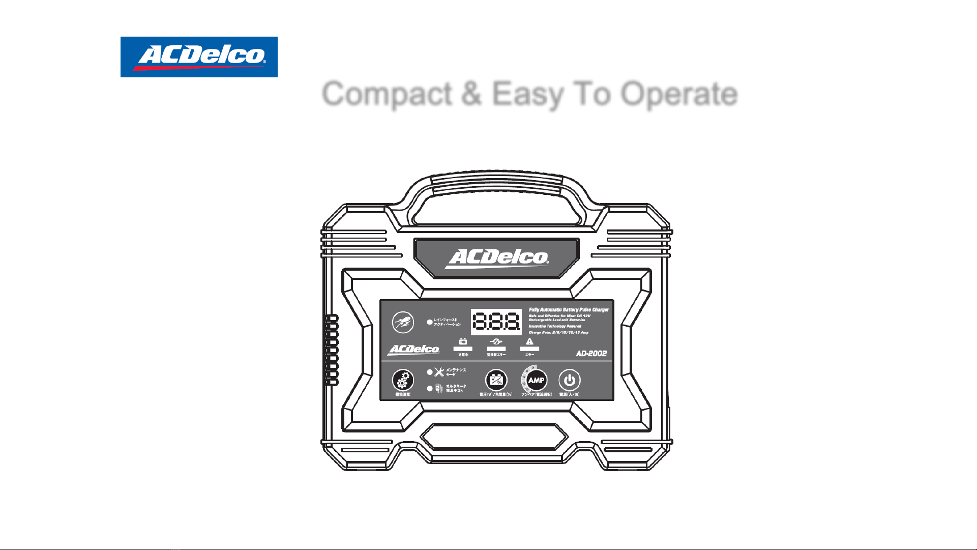
Compact & Light Weight Construction.
High (80%) AC-DC Power Conversion Rate.
Reduces Battery Plate Sulfation Through Pulse Charging.
Secures Stable Output Under Power (Grid) Variation.
6
A switching-mode power supply, SMPS:
An electronic power supply that incorporates a switching regulator to convert electrical power efficiently. Like other
power supplies, an SMPS transfers power from a source, like mains power, to a load, such as a personal computer,
while converting voltage and current characteristics. Unlike a linear power supply, the pass transistor of a switching-
mode supply continually switches between low-dissipation, full-on and full-off states, and spends very little time in
the high dissipation transitions, which minimizes wasted energy. Ideally, a switched-mode power supply dissipates no
power. Switching regulators are used as replacements for linear regulators when higher efficiency, smaller size or
lighter weight are required.

7
Desulfation
Pulse Charging –Battery plate Lead-sulfate crystalline build-ups are reduced, improving
battery condition.
Reinforced Activation –High voltage pulse charging loosens & removes lead-sulfate
residues from battery plates.
Results: Improved Battery chargeability & capacity
Prolonged battery lifespan
What is Sulfation?
For lead-acid battery, during use, small sulfate crystals form, but these are normal and not harmful. During
prolonged charge deprivation, however, the amorphous lead sulfate converts to a stable crystalline that deposits on
the negative plates. This leads to the development of large crystals, which reduces the battery’s active material that
is responsible for high capacity and low resistance. Sulfation also lowers charge acceptance. Sulfation will cost
longer charging time due to elevated internal resistance.
Sulfation
Desulfation

Reinforced Activation Mode
For batteries that cannot be charged normally, might be in poor condition due to
temporarily over draining or sulfation, manually switch on Reinforced Activation Mode.
The Reinforced Activation Mode removes sulfate residues from battery plates and
attempts to reactivate battery chargeability by higher voltage pulse charging .
Maximum charging time of 30 minutes is suggested to prevent battery damaging.
Remarks:
Reinforced activation is limited for those batteries:
* with physically damaged electrode(s).
* with exceedingly contaminated electrolyte solution.
* with insufficient electrolyte solution.
* over-period storage.
Do not exceed maximum charging time of 30-minutes.
Discontinue charging when battery housing temperature reaches or
above 45-50˚C.
8

Maintenance Charging Mode
9
Maintenance Charging Mode is switched on automatically in the last stage of 4-stage charging. It
can also be switched on manually by pressing “Function Key” upon battery connection.
Maintenance mode automatically shuts down after 36 hours of operation to avoid overheating.
Maintenance charging mode functions
1. Battery voltage maintenance
During cold weathers batteries have lower power output & engine cranking requires twice
as more current than normal. Batteries with lower charge rate tends to ignition failure.
Maintenance mode helps keep batteries in optimum condition ready for instant engine
ignition and use.
2. Improves battery chargeability
For batteries that remain unchargeable after Reinforced Activation Mode, might be in poor
condition due to over draining or sulfation lead to charging failure, showing Er1, Er2 or Er3
on the indicator. Manually switch on Maintenance Charging Mode to charges up the battery
slowly and safely , preparing it for normal 4-stage charging to it’s maximum capacity.
Remark: Discontinue charging when battery housing temperature reaches or above 45-50˚C.

Microprocessor monitors battery condition during charges for :
•Real-time battery voltage hold status
•Real-time battery charge percentage (%)
•Real time indication of failure occurrence during charges
Status information can be easily monitored through the 7 segment display and the LED
signals.
10
Real-time charging status helps users
monitor charge status in both voltage
holding and charge percentage.
Battery capacity level in % with 10%
increment from 10 to 90% and FUL
(i.e. 100%)
Error codes are shown on the
indicator when failures occur during
charging process. Refer to the Error
Code chart for further details (as in
the right table and manual).
Er0
System Error
- Contact Technician
Er1
Reverse polarity connection/Insufficient
battery voltage/
Loose terminal contact
Er2
Short Cell/Overload charge
Er3
Cell Failure/High level
sulfation
Er4
Overheating
Er5
Damaged
battery
【Error Code】
Built-In Battery Tester

Comparison –(1)
11
Item Linear Type Battery AC Delco Battery Charger
Appearance
Metal Box, Bulky, Heavy
Light, Compact
with Cable Compartment
Charging
One Stage
Multiple
-Stage Charging, Fast Charging
Power Efficiency
50%
or Less
Over 80%
Safety
Feature
Limited
Over Charge,
Short Circuit Protection Reverse
Polarity Protection
Battery
Tester
None
Diagnoses Battery Condition, Selects Charging Program for
Different Types Of Battery. Prevents Over
-Charge
Other
Features
Limited
Programmable Functions, Includes
Auto-Charge,
Reinforce Activation (Desulfation), Multiple Battery
Charge, Optimal Charging
Application
Separate
Charge for
Different
Types of Battery
Universal Charger for all 12
-Volt Battery Including
Start
-up, Deep Cycle, AGM, Maintenance-free, Gel Cell

Comparison –(2)
12
Sample Battery:
50Ah Maintenance-free
Resting Voltage after
discharge: 12V (discharging current 8A, discharged to 10.5V)
Specific Gravity: 1.14
Brand
Model
Charging
Rate
Charging
Time (Hr)
Specific
Gravity aft.
charge
Voltage 20Min.
after full charge
Charging
ACDelco I-7016 10A 04:19 1.28 13.3V 110%
Schumacher WM-
6000A 10A 04:25
1.23 13.1V
100%
Black & Decker VEC-
1087CBD
10A 03:57 1.20 12.7V
80%
* Data listed above are for reference only.

Safety Features
13
Reverse
-Polarity Protection
Protects the system from reverse
-polarity connection.
Over
-Charge Shutoff
Shuts off the circuit
s at full charge.
Short
-Circuit Guard
Short
-Circuit protection is programmed.
Electric Surge Protection
Surge
protection device is equipped.
Overheat
Suppression
Charging
shuts off before the unit overheats.
Spark
-Free clamps
Generates
no sparks at contact.
Table of contents
Other ACDelco Batteries Charger manuals