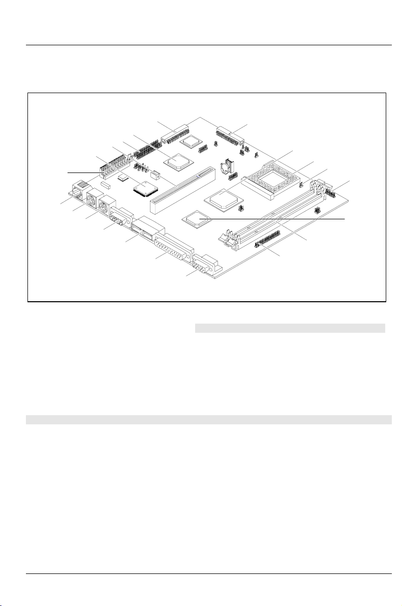
Internal ports and jumpers
A26361-K522-Z120-2-7419 English - 7
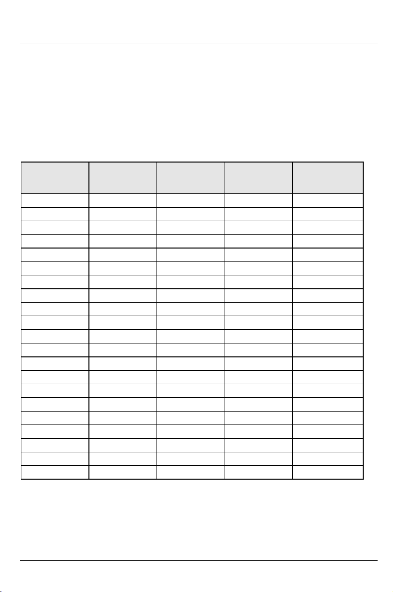
JP6 - Selecting the processor voltage
K6 processor type Jumper JP6 PLL- Processor voltage
K6-2 300 connected to 1 - 2 3.6V
Other K6 connected to 2 - 3 3.3V
JP4, JP5 - Selecting the clock speed
System clock Jumper JP5 Jumper JP4
100 MHz connected to 1 - 2 connected to 1 - 2
83 MHz connected to 1 - 2 connected to 2 - 3
66 MHz connected to 2 - 3 connected to 2 - 3
JP8, JP9, JP10 - Selecting the clock ratio
Clock ratio Jumper JP8 Jumper JP9 Jumper JP10
2,5 connected to 2 - 3 connected to 2 - 3 connected to 1 - 2
3,0 connected to 1 - 2 connected to 2 - 3 connected to 1 - 2
3,5 connected to 1 - 2 connected to 1 - 2 connected to 1 - 2
4,0 connected to 2 - 3 connected to 1 - 2 connected to 2 - 3
4,5 connected to 2 - 3 connected to 2 - 3 connected to 2 - 3
JP11 - LED jumper
JP11 MSG LED | Gnd | HD LED: Mail indicator/Hard disk indicator
Gnd | PWR OFF LED| PWR ON LED: On/Off indicator
JP12 - Switch jumper
JP12 ON/OFF switch
FN1/FN2 - Processor fan
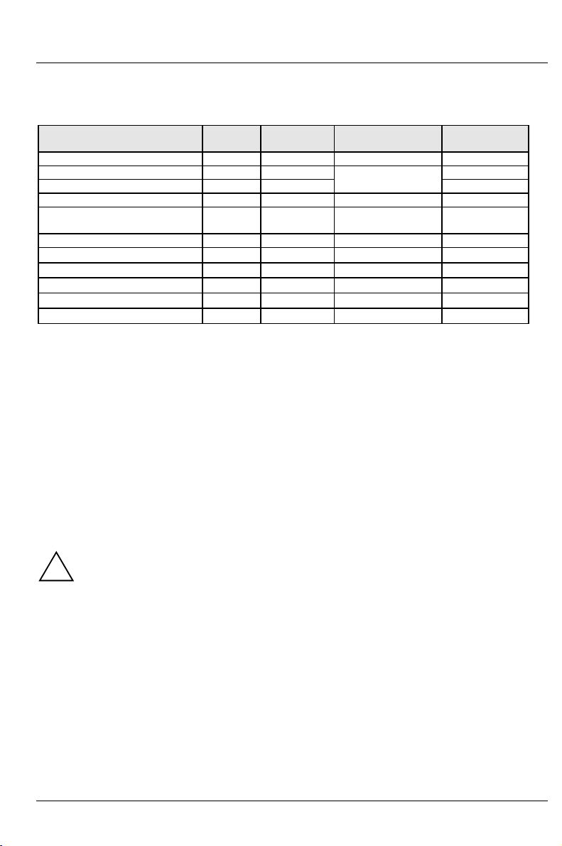
CN1 to CN31 - Internal ports and connectors
Internal
port Function Internal
port Function
CN1 Primary IDE connector CN13 Mouse port
CN2 Standby connector CN15 Keyboard port
CN3 Power supply CN18 USB port 2
CN4 Secondary IDE connector CN19 On/Off switch: 1 (-) 2 (+) 3 (-)
CN5 Floppy disk drive CN20 Parallel interface
CN6 Serial port 1 CN21 Video connector
CN7 USB port 1 CN22 AMC
CN8 LAN port CN28 Serial port 2
CN9 LAN indicator CN31 WOL connector
CN11 Modem Ring-In connector:
1(PWR2)3(Ring-in)4(GND)