manuals.online logo
Brands
  1. Home
  2. •
  3. Brands
  4. •
  5. Acewell
  6. •
  7. Motorcycle Accessories
  8. •
  9. Acewell ACE-HG20 User manual

Acewell ACE-HG20 User manual

ATV/Snowmobile/Motorcycle/Scooter Heated Grips
ACE-HG20/21/21T User Manual
Thanks for purchasing our heated grips. For smooth installation, we recommend you read the guide carefully and
follow the steps below. During installation, please be careful not to damage the wiring or pull wire out of the
terminals in the multipin plugs. If you have any doubts about the installation then please contact your grips supplier
for advice or arrange for professional installation.
Plug and play adaptor cables have been developed for some vehicle. Check with your grip supplier which they can
offer.
There are three versions of the grips as follows:
ACE-HG20 (Motorcycle/ Scooter): 7/8”handlebars with twist grip throttle
ACE-HG21 (ATV/Snowmobile/PWC): 7/8”handlebars with thumb throttle
ACE-HG21T: 7/8”handlebars with thumb throttle including a thumb warmer
** PLEASE NOTE THE FOLLOWING SAFETY INFORMATION **
•DO NOT HOLD THE GRIPS WITH BARE HANDS! ALWAYS WEAR GLOVES TO AVOID BURNS!
•SWITCHING THE GRIPS ON FOR MORE THAN A FEW SECONDS IF NOT FITTED TO THE
HANDLEBARS WILL CAUSE DAMAGE TO THE GRIPS AND MAY WARP THE INNER TUBE
•THE CONTROL BUTTON IS AN ELECTRONIC MICROSWITCH AND ONLY REQUIRES A GENTLE
PRESS. PLEASE DO NOT TRY TO PULL THE BUTTON OUT TO CLEAN IT, DOING SO WILL
DESTROY THE SILICONE AND IT WILL NOT BE POSSIBLE TO REINSTALL THE BUTTON.
COMPONENTS
1 ×Left Grip with temperature controller button.
1 ×Right grip.
1 ×Thumb warmer kit (ACE-HG21T only)
1 ×Connecting wire or bike specific plug and play cable.
2 ×Cable tie
2 ×Bar-end cap
FEATURES
!ACEWELL grips fit any 7/8”/ 22mm handlebars to work with existing twist grip throttle tubes (ACE-HG20) or
thumb throttle (ACE-HG21).
!Push button temperature controller and power level display built into left grip allows an easy installation and no
need for additional switches.
!5 levels of grip heat temperature with fast-heat at power on.
!5 color illumination of the control button to indicate selected temperature.
!The integrated control/display module keeps the original look of the bike but still allows full functionality of the
grips.
!Classic slimline design which suits all types of motorcycle, scooter, ATV, PWC and Snowmobile.
!Optional thumb heat pad available.
!Hard wearing and anti-slip silicone outer layer giving soft but durable texture.
!Low voltage detection -the grips automatically switch off to help protect against a flat battery
!Simple installation with minimal wiring and detailed fitting instructions.
INSTALLATION & WIRING
ACE-HG20 & HG-21
1. Use the appropriate tool to remove the existing grips.
Clean the handlebars and throttle tube as applicable with solvent and ensure the bars are free of residue and glue.
2. Slide the Right grip onto throttle sleeve (HG20) or handlebar (HG21) and then the Left grip onto the handlebar.
Apply Epoxy into the handlebar or throttle sleeve to hold the grips securely in place.
Align the grips so that the cables point downwards and the control switch (button) can be easily pressed with your
thumb
3. Connect the plug and play cable or the power tails to the left grip. If using the power tails then the black wire
should connect to negative (battery -) and red wire to positive (+12v)
The grips feature an automatic power off function to save your battery so they can be connected to either an
ignition live or directly to the battery depending on your preference
4. Connect the Right twist throttle grip to the Left grip.
5. After installation, swing the handlebar left to right to ensure nothing obstructs the movement.
ACE-HG21T
Follow steps 1-3 above
4. The HG21T includes a thumb warmer.
5. Use solvent to clean the thumb throttle, remove the backing paper from the heater and stick to the thumb throttle
using the self-adhesive pad.
6. Cover the heat pad with the supplied heat shrink tubing, and shrink into place using a hot air gun or flame.
7. Plug the thumb heater inline between the left and right grips
8. After installation, swing the handlebar left to right to ensure nothing obstructs the movements.
OPERATION
●AUTO-ON/OFF –BATTERY SAVER FUNCTION:
These heated grips feature a microprocessor controlled battery saver function, which tries to ensure that you don’t
incur a flat battery due to having your heated grips switched on when the engine is not running.
This function can be disabled it not required, or customized to the voltages on your vehicle.
The grips measure the voltage on the wire entering the grip. Due to voltage drops, the voltage detected when the
grips are connected directly to a battery will be different to the voltage detected when connected after the ignition
key.
Follow the instructions in the “VOLTAGE SETTING” section below to set up the battery saver function.
●POWER ON
Press and hold the button for 5 secs, the red LED will flash once per second for 4 minutes indicating that the grips
are in start-up fast-heat mode then return to the last set heat level.Pressing a button during the first 4 minutes takes
the grips out of fast-heat mode
●AUTO-ON/OFF:
If the voltage drops below the “OFF” voltage for more than 6 seconds then the red LED light in the grip will flash
quickly (twice per second) for 30 seconds while continuing to heat the grips
After 30 seconds the heat will switch off and the red LED will flash slowly for 10 minutes to indicate standby mode
If the engine is restarted before the 10 minutes of standby mode expires then the grips switch back on to their preset
heat level and all timers are reset.
If the engine is not restarted before the standby mode expires then the grips enter “SLEEP MODE”, the LED will
extinguish and you’ll need to press the power button to switch the grips on again once the engine has been restarted.
●CHANGE THE HEAT LEVEL
Press the button to select your desired heat level.
Heat Level
1
2
3
4
5
LED display
Blue
Cyan
Purple
Yellow
Red
Heat / PWM %
20%
40%
60%
80%
100%
(PWM = Pulse width modulation –an energy efficient way to regulate the heat)
●POWER OFF
Press and hold the button for 3 secs.
●VOLTAGE SETTING (see the below table):
Choose a voltage setting that works best for your vehicle, try to find the setting which brings your grips on when the
engine starts and revs are increased, but only switches them off when the engine stops (not at idle). Don’t forget
headlights on and off will affect the voltage if you wire into the bike near the headlight supply wires.
If you find that the grips switch off too often then lower the voltage setting.
If the grips don’t switch off when the engine stops then raise the voltage setting.
When you receive your new grips the factory default setting is Purple and they will switch off at 12.2v
Press the button for 5 seconds to switch on the grips and then immediately press for another 10 seconds to enter setup
mode. While pressing the button for 10 seconds the LED will go out and then start flashing green 5 times.
When the green flashing LED is observed release the button and the LED will illuminate to show the selected
voltage mode.
Press the control button repeatedly to switch between voltage modes then press and hold the control button for 3
seconds to save the mode and switch off the grips. Press the power button again for 5 seconds to switch them back on.
If you don’t save the setting by holding the button for 3 seconds the grips will switch off after 60 seconds.
Voltage Settings
Display
Off Volts
On Volts
Green
Battery saver disabled
Blue
11.8v
12.6v
Cyan
12.0v
12.8v
Purple
12.2v
13.0v
Yellow
12.4v
13.2v
Red
12.6v
13.4v
White
12.8v
13.6v
SPECIFICATION
Power Input: DC 12V only, max 50W
Fuse Type: 5A
Grip Material: LSR (silicone) outer layer

This manual suits for next models

2

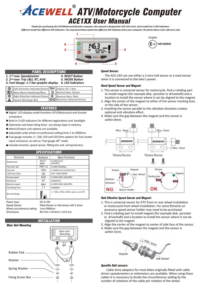
Other Acewell Motorcycle Accessories manuals

Acewell CV080 2 Series User manual

Acewell

Acewell CV080 2 Series User manual

Acewell ACE-43 Series User manual

Acewell

Acewell ACE-43 Series User manual

Acewell ACE-2XX User manual

Acewell

Acewell ACE-2XX User manual

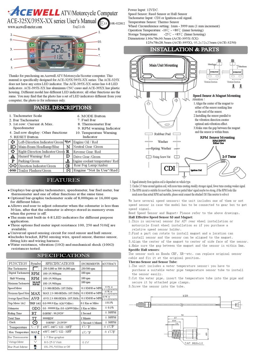
Acewell ACE-325X-XX series User manual

Acewell

Acewell ACE-325X-XX series User manual

Acewell MD-052-2 Series User manual

Acewell

Acewell MD-052-2 Series User manual

Acewell ACE-3252 User manual

Acewell

Acewell ACE-3252 User manual

Acewell ACE-3200 Series User manual

Acewell

Acewell ACE-3200 Series User manual

Acewell ACE-100- User manual

Acewell

Acewell ACE-100- User manual

Acewell ACE1 Series User manual

Acewell

Acewell ACE1 Series User manual

Acewell ACE-6 Series User manual

Acewell

Acewell ACE-6 Series User manual

Acewell MD-052-2XX Series User manual

Acewell

Acewell MD-052-2XX Series User manual

Acewell ACE-1500 User manual

Acewell

Acewell ACE-1500 User manual

Popular Motorcycle Accessories manuals by other brands

National Cycle VStream N20005 Installation and owner's manual

National Cycle

National Cycle VStream N20005 Installation and owner's manual

Kuryakyn 4162 Installation

Kuryakyn

Kuryakyn 4162 Installation

Leatt 3.5 manual

Leatt

Leatt 3.5 manual

ZTechnik Quantum Z2360 quick start guide

ZTechnik

ZTechnik Quantum Z2360 quick start guide

Xenith X2E Player's manual

Xenith

Xenith X2E Player's manual

RDMOTO BN1 quick start guide

RDMOTO

RDMOTO BN1 quick start guide

hepco & becker Locl it 506529 00 01 quick start guide

hepco & becker

hepco & becker Locl it 506529 00 01 quick start guide

Dynafit CARBONIO User instructions

Dynafit

Dynafit CARBONIO User instructions

STAMOS COLOUR GLASS X-100B user manual

STAMOS

STAMOS COLOUR GLASS X-100B user manual

N-Com B602 quick guide

N-Com

N-Com B602 quick guide

MSA Cairns 1010 operating manual

MSA

MSA Cairns 1010 operating manual

hepco & becker 6539510 00 01 manual

hepco & becker

hepco & becker 6539510 00 01 manual

hepco & becker 6616519 01 01 quick guide

hepco & becker

hepco & becker 6616519 01 01 quick guide

R&G RAD0172 Fitting instructions

R&G

R&G RAD0172 Fitting instructions

Sena SMH3 user guide

Sena

Sena SMH3 user guide

DYNATEK DFS7-9P manual

DYNATEK

DYNATEK DFS7-9P manual

National Cycle Quantum VStream N20121 manual

National Cycle

National Cycle Quantum VStream N20121 manual

Wunderlich 42380-000 FITTING INSTRUCTION

Wunderlich

Wunderlich 42380-000 FITTING INSTRUCTION

manuals.online logo
manuals.online logoBrands
  • About & Mission
  • Contact us
  • Privacy Policy
  • Terms and Conditions

Copyright 2025 Manuals.Online. All Rights Reserved.