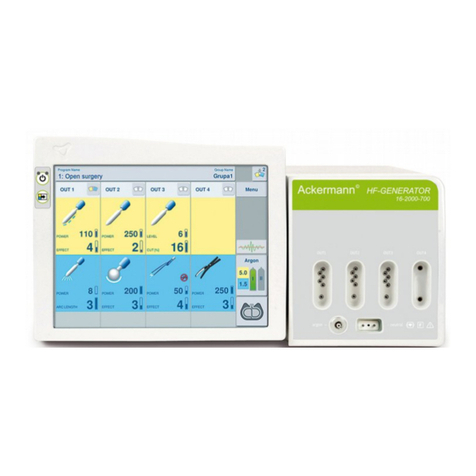
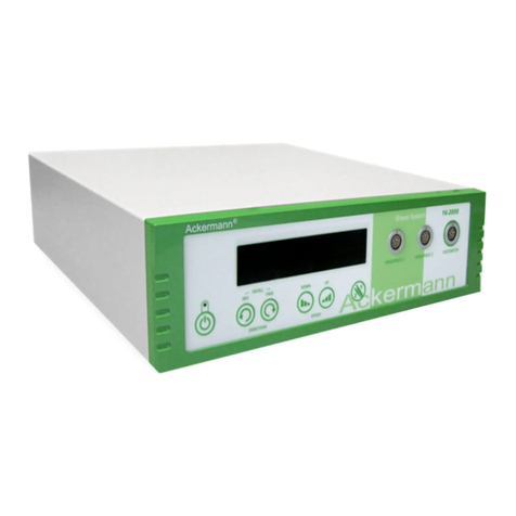
ACKERMANN 16-2000-120 User manual

USER MANUAL 16-2000-120
HIGH FREQUENCY UNIT WITH 110V/ 220V
for cutting and coagulation in surgical procedures

These operating instructions contain information that is subject to copyright.
All rights are reserved.
This manual should not be photo-copied, duplicated on microfilm or otherwise copied or distributed,
completely or in part, without the approval of the manufacturer. The manufacturer will appreciate any errors or
anything unclear in this operating manual being pointed out to us by users of our products.
Due to the continuing progress and development of our products, we reserve all rights for technical
alterations.
Rev. 02/2016
SERVICE ADRESS: Ackermann Instrumente mbH
Eisenbahnstraße 65-67
78604 Rietheim-Weilheim
ermany

USER MANUAL 16-2000-120 Rev. 02/2016
CONTENTS AGE
1. INTENDED USE 5
2. ELECTROSUR ERY BASICS 6
2.1. MONOPOLAR OPERATION 6
2.2. BIPOLAR OPERATION 6
3. TECHNICAL SPECIFICATIONS 7
4. SYMBOLS IN THE INSTRUCTION FOR USE AND ON THE UNIT 9
5. ACCESSORIES FOR ELECTROSUR ICAL
PROCEDURES 9
5.1. NEUTRAL ELECTRODE CABLE 1 0
5.2. INSTRUMENT CABLE 1 0
5.3. ACKERMANN SMART DETECTION ................................ 10
5.4. FOOTSWITCH . 11
6. LIST OF ACCESSORIES . 12
7. UNIT APPEARANCE AND CONSTRUCTION 12
7.1. FRONT
PANEL . 12
7.2. BACK PANEL 13
8. PREPARIN THE UNIT
FOR OPERATION 13
8.1. PLACIN THE UNIT ON A TROLLEY (AS
AN OPTION) ............... 13
8.2. CONNECTIN THE POWER CABLE ................ 14
8.3. CONNECTIN ACCESSORIES ................. 14
8.4. LEVEL
SETTIN S .............. 15
9. UNIT OPERATION AND
ELECTROSUR ICAL
PROCEDURES . 15
9.1. SWITCHIN ON THE
UNIT ................ 15
9.2. VOLUME ADJUSTMENT ................ 16
9.3. NEUTRAL
ELECTRODE MONITORIN ................ 16
9.3.1. DISPOSABLE ELECTRODES ....................... 17
9.3.2. REUSABLE ELECTRODES .................... 18
9.3.3. NEUTRAL ELECTRODE
APPLICATION
PRINCIPLES .............. 19
9.4. UNIT OVERLOAD CONTROL . . 20
9.5. MONOPOLAR CUTTIN ............... 21
9.6. MONOPOLAR COA ULATION ............... 22
9.7. BIPOLAR COA ULATION ............... 23
9.8. SWITCHIN OFF THE
UNIT .............. 24
10. PROTECTION MEASURES AND
WARNIN S 25
11. TECHNICAL INSPECTION, WARRANTY
AND SERVICE 27
12. UNIT AND ACCESSORIES MAINTENANCE . 34
AGE 3 OF 39

USER MANUAL 16-2000-120 Rev. 02/2016
12.1. RECOMMENDED CLEANIN AND STERILISIN A ENTS FOR REUSABLE
ELECTROSUR ICAL ACCESSORIES 34
12.1.1.. M ANUAL
WASHIN 34
12.1.2.. MECHANICAL
WASHIN 35
12.1.3.. AUTOCLAVE STERILIZATION 35
12.1.4.. FORMALDEHYDE STERILISATION 35
13. ENVIRONMENTAL REQUIREMENTS . 36
14. ELECTROMA NETIC EMISSIONS 36
15. ENVIRONMENTAL PROTECTION UIDELINES 39
SYMBOLS IN THIS INSTRUCTION FOR USE
IM ORTANT INFORMATION
WHAT TO DO
WHAT NOT TO DO
WARNING
AGE 4 OF 39

USER MANUAL 16-2000-120 Rev. 02/2016
1. INTENDED USE
The 16-2000-120 electrosurgical unit operates using a high-frequency current flow. It is intended for cutting
and coagulation in surgical procedures.
The 16-2000-120 unit enables the following operation modes:
- pure cutting
- cutting with hemostasis
- soft coagulation
- forced coagulation
- bipolar coagulation
The unit is equipped with a CF (floating) output so that it can be used on the central nervous system and
the heart.
AGE 5 OF 39

USER MANUAL 16-2000-120 Rev. 02/2016
2. ELECTROSURGERY BASICS
Currently, electrosurgery is a technique used in nearly all kinds of surgical procedures. In order to use
electrosurgery effectively, it is necessary to learn and understand it, and to apply the safety rules designed for
maximum protection of both the surgeon and the patient.
An electrosurgical unit is a device that uses electricity to generate high-frequency (HF) alternating current.
The thermal effect caused by the HF current flowing through the tissue is used for tissue cutting or
coagulation. An electrosurgical unit generates alternating current of frequency higher than 300 [kHz], so there
is no risk of unintended effect of muscle and nerve electrolysis/stimulation.
When working with an electrosurgical unit generating high-frequency current, always remember
the two fundamental rules:
- the current flows along all the available paths,
- the HF leakage current flows between two adjacent conductors even if they are separated
from each other.
2.1. MONO OLAR O ERATION
In the monopolar mode, the HF current is delivered to the tissue by the
active electrode. The cutting or coagulation effect results from the
concentration of the high density HF current on the small surface of the
active electrode. This causes an increase of temperature and water
evaporation from the tissue in the direct vicinity of the active electrode
and eventually results in haemostasis and arrest of bleeding, or cutting of
the tissue.
Subsequently, the HF current flows to the neutral electrode where it is
dispersed. In this way, the density of the HF current decreases and no
unintended thermal effect occurs at the site of the neutral electrode
application. From the neutral electrode the HF current returns to the unit.
2.2. BI OLAR O ERATION
When the unit operates in the bipolar mode, the HF current flows
between the two jaws of a bipolar instrument and concentrates
exclusively on the small area located between them. In the bipolar mode
the dangerous current flow through the patient’s body to the neutral
electrode does not occur, so the risk of burns occurring outside the
immediate surgical area is minimised. Thus, the bipolar coagulation
modes are safer than the monopolar modes and they are particularly
recommended for procedures involving patients with cardiac pacemakers
or for procedures performed on organs of a small cross-section area. In
the bipolar mode, the neutral electrode is not required.
AGE 6 OF 39

USER MANUAL 16-2000-120 Rev. 02/2016
3. TECHNICAL S ECIFICATIONS
OWER SU LY
Power supply voltage 220-240 [V] ± 10% 50/60 [Hz] or
optionally
110-120 [V] ± 10% 50/60 [Hz]
Rated power consumption 300 [VA]
SAFETY CONDITIONS
Electric shock protection:
Class I
Degree CF
Degree of casing protection IP2X
Low-frequency leakage currents according to EN 60601-1
High-frequency leakage currents according to EN 60601-2-2
enerator operation frequency 333 [kHz]
Defibrillation impulse resistance according to EN 60601-1
NEM system Neutral electrode monitoring.
Maximum resistance at which the unit will operate: 160
[Ohm]
AUTOTEST Automatic test of the unit and accessories after power
supply is connected. Display of service codes.
OVERLOAD Overload protection
CUTTING
PURE CUT Pure monopolar cutting 9 levels
120 [W] for 300 [Ω], max 700 [Vp]
BLEND CUT Monopolar cutting with hemostasis 9 levels
120 [W] for 300 [Ω], max 1500 [Vp]
COAGULATION
FORCED COA Forced monopolar coagulation 9 levels
120 [W] for 300 [Ω], max 1600 [Vp]
SOFT COA Soft monopolar coagulation 9 levels
120 [W] for 50 [Ω], max 225 [Vp]
AGE 7 OF 39

USER MANUAL 16-2000-120 Rev. 02/2016
BI-COA Bipolar coagulation 9 levels
120 [W] for 50 [Ω], max 225 [Vp]
WEIGHT AND DIMENSIONS
Length 330 [mm]
Width 285 [mm]
Height 105 [mm]
Weight 3.5 [kg]
WORKING LIFE 10 years
The technical specifications listed in the table may change as our products develop.
AGE 8 OF 39

USER MANUAL 16-2000-120 Rev. 02/2016
4. SYMBOLS
Defibrillation-proof type CF applied part
The generator output is floating (isolated) with respect to ground
Caution
Dangerous voltage
Manufacturer
Operating instructions
Follow instructions for use
Non-Ionizing Radiation
Serial number
Catalogue number
Equipotentiality
Conforms to Directive 93/42/EEC
The product may not be disposed of as normal household garbage
Ackermann HF units are manufactured in protection class CF I. It is the highest class of patient protection
against electric shock from electromedical devices. Type CF applied parts can be used in contact with any
part of the patient’s body including the heart.
AGE 9 OF 39

USER MANUAL 16-2000-120 Rev. 02/2016
5. ACCESSORIES FOR ELECTROSURGICAL ROCEDURES
Ackermann only allows the use of Ackermann accessories or those available in the catalogue of
the our company.
In case of doubts concerning the authorisation of a given accessory and the manner of
connecting it, please contact the manufacturer or a distributor.
Ackermann offers high-quality electrosurgical accessories to be used with the Line 16-2000-120, enabling the
implementation of surgical, gynaecological, dental and other procedures.
The maximum voltage of active accessories should be checked before they are connected to
the unit. The operating voltage of the accessories should not be lower than the maximum
output voltage of the unit.
5.1. NEUTRAL ELECTRODE CABLE
disposable neutral electrode plug
reusable neutral electrode plug
The connection sockets of the neutral electrode output (Fig. 4, item 3):
For more information on the neutral electrode, see section 8.3 “Neutral
electrode monitoring”.
5.2. INSTRUMENT CABLE FOR UNIVERSAL ASD SOCKETS
universal ASD plug
The universal outputs with automatic instrument detection are made
according to the Ackermann Smart Detection standard (Fig. 4, item 4 and
5).
AGE 10 OF 39

USER MANUAL 16-2000-120 Rev. 02/2016
5.3. ASD – ACKERMANN SMART DETECTION
The sockets 16-2000-120 are equipped with an instrument detection system – ASD. It detects and identifies
the connected instrument.
Both sockets (OUT1 and OUT2) support monopolar and bipolar modes.
The mode settings are general for the unit rather than for instruments, as after two monopolar instruments are
connected to both ASD sockets they use the same settings fixed on the CUT and COA panel. After two
bipolar instruments are connected the settings on the BICOA panel apply to both of them.
After the supported ASD instrument is connected the units emits an acoustic signal (a rising tone). After the
ASD instrument is disconnected the unit emits an acoustic signal (a falling tone).
In the absence of an instrument or if an unsupported instrument is connected, the functions of the unit cannot
be activated.
A list of supported ASD instruments (catalogue 16-2):
Monopolar: 16-2003-100, 16-2003-160, 16-2000-110, 16-2003-121, 16-2003-122
Bipolar: 16-2003-138, 162000-1310ASD
(The list of supported instruments can change as the unit software is modified.)
During activation, the diodes over the active footswitch socket selection button change their function and
signal the mode (cutting and coagulation) and the socket (OUT1 or OUT2) in which the unit has been
activated (e.g. for cutting at socket 1 a yellow diode flashes over OUT1, etc.). This shows which instrument is
active in the case where two monopolar instruments or two bipolar instruments are connected to both sockets
(the CUT diode alone signals that monopolar cutting has been activated, but does not indicate in which
socket).
5.4. FOOTSWITCH
16-2000-120 can be used with a wired footswitch.
The footswitch is connected to the socket situated on the back of the unit (Fig. 5, item 8).
6. LIST OF ACCESSORIES
- Power cable, 4 m (1x)
- Instructions for use (1x)
7. UNIT A ERANCE AND CONSTRUCTION
The unit casing is made of metal. It has no ventilation holes. The front panel is made of plastic. It is easy to
keep the unit clean, as generally available disinfectants can be used to clean it.
AGE 11 OF 39

USER MANUAL 16-2000-120 Rev. 02/2016
7.1. FRONT ANEL
Figure 4. Front view
The front panel of the unit contains the following (Fig. 4):
(1) standby button
(2) neutral electrode monitor NEM
(3) neutral electrode socket
(4) monopolar electrode socket
(5) bipolar electrode socket
(K1) pure cutting button
(K2) button for cutting with hemostasis
(K5) forced coagulation button
(K6) soft coagulation button
(K4)+(K3) cutting level adjustment button – enhancement (K4) and reduction (K3)
(K8)+(K7) monopolar coagulation level adjustment button - enhancement (K8) and reduction (K7)
(K10)+(K9) bipolar coagulation level adjustment button - enhancement (K10) and reduction (K9)
(K11) footswitch control buttons: monopolar or bipolar outputs
(D1) monopolar cutting level display
(D2) monopolar coagulation level display
(D3) bipolar coagulation level display
AGE 12 OF 39

USER MANUAL 16-2000-120 Rev. 02/2016
7.2. BACK ANEL
Figure 5. Back view .
The back panel of the unit contains the following (Fig. 5):
(6) manufacturer’s rating plate
(7) main power switch
(8) footswitch socket
(9) (optional wireless footswitch module – not available)
(10) service port
(11) additional grounding pin
(12) fuse socket
(13) power cable socket
8. RE ARING THE UNIT FOR O ERATION
In order to make the unit ready to operate, connect the power cable and accessories.
8. 1. LACING THE UNIT ON A TROLLEY
16-2000-120 can be placed on a trolley (16-2000-1500). The steel coated trolley is equipped with a movable
base with a locking mechanism on the rubber rolls. It has stabilising pins to protect the unit from falling and a
case with small shelves for accessories.
AGE 13 OF 39

USER MANUAL 16-2000-120 Rev. 02/2016
8. 2. CONNECTING THE OWER CABLE
As the only one, the power cable can be plugged or unplugged only when the unit is off. The unit conforms to
class I electric shock protection and requires one phase power supply with sockets equipped with a
grounding pin. The power supply socket is located on the back panel of the casing (Fig. 5, item 13).
In order to avoid the risk of electric shock, the unit must be connected to the mains with
protective grounding.
The unit does not need to be connected to an additional protective earth contact (Fig. 5, item 11). An
additional protective earth contact serves to ground the unit when an ungrounded power socket is used or at
places where a shock protection system requires the connection of an additional equipotential bonding
conductor.
8. 3. CONNECTING ACCESSORIES
Fig. 7 explains how accessories should be connected.
Figure 7. The manner of connecting accessories
AGE 14 OF 39

USER MANUAL 16-2000-120 Rev. 02/2016
8. 4. LEVEL SETTINGS
The unit is equipped with a system for automatic output power adjustment depending on the operating
conditions. The processor measures in real time all the operating parameters and adjusts on an ongoing
basis the delivered power, current and voltage so as to attain the selected level. The effect set by the user
and visible on the screen is the upper voltage limit for a given mode.
Before starting a procedure, set the appropriate level. It is set separately for cutting, monopolar coagulation
and bipolar coagulation procedures. The level can be adjusted within the interval of 1 to 9.
The selected output level should be adequate so as to attain the intended objective. In electrosurgery, a
patient can be at risk when the applied output level is too low. In such a case, cutting and coagulation take
longer, which can cause an excessive thermal invasion into the surrounding tissue. Therefore, the setting
should be selected according to the operator’s experience, by referring to the appropriate clinical
recommendations or the results of an appropriate practice.
The settings are changed using the keys with arrows:
→ effect enhancement
→ effect reduction
Before the unit is applied for the first time it is recommended to explore the levels of different
settings by carrying out trials on fresh beef.
9. UNIT O ERATION AND ELECTROSURGICAL ROCEDURES
9.1. SWITCHING ON THE UNIT
To switch the unit on, use the main power switch located on the back panel (Fig. 5, item 7) and the stand-by
button on the front panel (Fig. 4, item 1). The unit is started by pressing the stand-by button. The unit starting
process takes a few seconds. During this time, an internal test of the unit and the connected accessories is
run.
Accessories can also be connected to a unit which has been switched on, but certainly relevant safety
conditions must be satisfied. Care must be taken then to prevent the possible starting of the unit by
accidentally pressing the button or the footswitch.
AGE 15 OF 39

USER MANUAL 16-2000-120 Rev. 02/2016
9.2. VOLUME ADJUSTMENT
The unit has a volume adjustment feature. It only covers activation signals. In order to
change the volume, press and hold down the pure cutting button for at least 2 [s]. Then,
using the arrows select the target volume of the unit. Five volume levels can be
selected, where u1 is the lowest permissible level and u5 is the highest permissible
level. In all the modes, alert/error messages are sounded at the loud level. To ensure
that the unit saves the new setting, wait for 3 [s] or press the pure cutting button again.
Figure 8. Volume adjustment.
9.3. NEUTRAL ELECTRODE MONITORING
In the monopolar operating mode, the unit requires a neutral electrode to be connected. Ackermann units are
equipped with a neutral electrode application monitoring system. The NEM system installed in Ackermann HF
units is designed for use with Ackermann disposable neutral electrodes with the catalogue number
16-2000-1212DFL. Only these neutral electrodes are compatible with our system.
The manufacturer only allows the use of disposable neutral electrodes with the catalogue
number 16-2000-1212DFL for adult patients and children.
The use of disposable neutral electrodes, enables the equal distribution of a high-frequency current on the
entire electrode surface, in combination with the NEM system, guarantees the continuous monitoring of
neutral electrode adhesion and ensures the maximum patient safety during the procedure.
AGE 16 OF 39

USER MANUAL 16-2000-120 Rev. 02/2016
Neutral electrodes other than those mentioned above may not ensure proper cooperation with the NEM
neutral electrode safety system.
The manufacturer is not responsible for the use of Ackermann HF units with neutral electrodes other than
those mentioned above, or for any incidents resulting from such use.
If the neutral electrode is correctly connected, then a green diode is on at the neutral electrode indicator. If the
neutral electrode is not connected or the electrode with adhesion monitoring is incorrectly applied, after the
unit has been started a green diode is on, a modulated acoustic signal can be heard and the message “EL
NEU-[]” is displayed. It is impossible to activate the unit in the monopolar mode unless the neutral electrode is
correctly connected. If such a message appears during the operation of the unit, stop the operation and check
the connection of the neutral electrode.
An important advantage of the neutral electrode monitoring system is that the monitoring is performed on a
continuous basis, also during the operation of the unit. The neutral control monitoring system does not affect
the operation in the bipolar mode.
Figure 9. The message that the neutral electrode is not connected correctly.
9.3.1. DIS OSABLE NEUTRAL ELECTRODES
The neutral electrode must not be modified in any way. Once applied, the electrode should not
be transferred to another place. Never use electrodes after their expiry date. Do not use force
to remove the electrode. It should be unstuck carefully.
Before applying a disposable neutral electrode, dry the application site very carefully. When
alcohol-based disinfectants have been used wait for a while to let the alcohol evaporate. When
using disposable electrodes, always check their expiry date. A disposable electrode can only be
used once.
The neutral electrodes are supplied in closed sachets. After a package has been opened an
electrode must be used within 15 days. After that time, the conductive substance dries out and
does not ensure sufficient conduction. Disposable electrodes should be applied carefully. If it is
necessary to apply the electrode in a different place, use a new electrode.
AGE 17 OF 39

USER MANUAL 16-2000-120 Rev. 02/2016
Check the neutral electrode application and the connected cables every time the patient’s
position has been changed. Protect the neutral electrodes against wetting during the procedure.
9.3.2. REUSABLE NEUTRAL ELECTRODES
When performing surgical procedures:
- requiring high power settings (e.g. TURP);
- posing a risk of flooding the neutral electrode with liquids;
- in which the staff is not able to control the neutral electrode application;
- on children
THE USE OF REUSABLE NEUTRAL ELECTRODES IS NOT ALLOWED
When using one-piece silicone electrodes, the surgical team is fully responsible for the correct
application of an electrode. Therefore, take special care to correctly attach the neutral electrode
to avoid burns at its application site during the procedure. The application of a one-piece
neutral electrode should be monitored throughout the duration of the procedure.
Before applying a neutral electrode, read the instructions for use supplied by its manufacturer.
A reusable one-piece neutral (silicone) electrode does not enable the application to be
monitored by the unit, i.e. to control its adhesion to the patient’s body. Only a correct electrode
connection to the unit is monitored.
The neutral electrode must not be wetted or wrapped with anything. Do not spread any
additional conductive gel on the surface of the neutral electrode. When disconnecting the
neutral electrode, never do it by pulling the cable. Under no circumstances try to repair the
neutral electrode by yourself.
Examine the condition of the neutral electrode and the connection cable before application. Do
not use them in case of visible surface defects on the electrode surface or damaged insulation.
Attach the reusable silicone electrode in such a way as to prevent it from moving spontaneously
– use a special tape for fixing a neutral electrode. Prevent any fluid intrusion between the
electrode and the patient’s body. Reusable neutral electrodes should be disinfected before use
(see section 12 “Unit and accessories maintenance”).
Remember that a silicone electrode loses in time its conductive properties as active substances
are washed out from the silicone. Such an electrode increases the risk of patient burns.
Therefore, reusable electrodes should be subjected to regular inspections, along with units.
Read the manufacturer’s instructions for use before applying a neutral electrode.
ALWAYS comply with the manufacturer’s instructions on the package of the neutral
electrode.
AGE 18 OF 39

USER MANUAL 16-2000-120 Rev. 02/2016
9.3.3. NEUTRAL ELECTRODE A LICATIOM RINCI LES
Do not apply the electrode on scar tissue, cuts or scratches.
Do not apply the electrode in areas which are concave, particularly convex or bony.
Do not apply the electrode on excessively hairy skin – if necessary, remove the hair.
Do not use it at sites with excessive fatty tissue, e.g. the abdomen or buttocks.
Do not apply it on the surface of the skin under which there are implants.
When disconnecting the neutral electrode, never do it by pulling the cable.
The neutral electrode cannot touch any conductive elements, e.g. metal parts of the table.
The neutral electrode should be so applied as to ensure that it adheres to the patient’s body
with its entire surface.
The neutral electrode should always be applied on clean and degreased skin.
The neutral electrode should be applied in smooth, well vascularised areas, without skin
breakdown or pits, for instance, on the upper arm or thigh.
The neutral electrode should be placed in the vicinity of the operative field but at least 20 [cm]
from it.
When applying the neutral electrode make sure that it faces the operative field with its longer
edge.
A LICATION SITES OF A DIS OSABLE NEUTRAL ELECTRODE
correct
incorrect
→ Correct sites of the neutral electrode application in patients with a
cardiac pacemaker.
AGE 19 OF 39

USER MANUAL 16-2000-120 Rev. 02/2016
→ Correct sites of the neutral electrode application on adult patients.
→ Correct sites of the neutral electrode application on a child.
9.4. UNIT OVERLOAD CONTROL
The unit is equipped with a system limiting its operation time to prevent it from overheating (OVERLOAD).
The limitation depends on the level settings and the type of procedure carried out. When unit overload occurs
it is signalled by a modulated pulsed acoustic signal and a message “OVE LOA”. The unit forces an
interruption in the procedure until the message disappears and the acoustic signal stops (about 30 [s]).
Figure 10. The message about unit overload.
AGE 20 OF 39
Table of contents
Other ACKERMANN Medical Equipment manuals
Popular Medical Equipment manuals by other brands

baxter
baxter DUPLOSPRAY Quick reference guide

Smith Medical
Smith Medical Medex LogiCal Quick operation guide

SOPHION BIOSCIENCE
SOPHION BIOSCIENCE QPatch Compact installation guide

Custo Med
Custo Med Custo Guard 1/3 operating manual

DT Research
DT Research 507T Basic operation guide

VSSI
VSSI V-Top instruction manual