ACKERMANN FUSION INSUFFLATOR User manual

USER MANUAL 16-2045
FUSION INSUFFLATOR

USER MANUAL 16-2045 Rev. 09/2017
Page 2of 25
Contents
1Preface ____________________________________________________3
2About the device _____________________________________________4
3Safety instructions____________________________________________5
4Regulatory advice ____________________________________________8
5Installing the device___________________________________________9
6Operating guidelines _________________________________________10
7Special Features ____________________________________________13
8Suggested decontamination procedures__________________________17
9After-sales service and maintenance____________________________ 17
10 Troubleshooting ____________________________________________ 18
11 Technical characteristics______________________________________19
12 Electromagnetic compatibility__________________________________ 20
13 Symbols___________________________________________________24

USER MANUAL 16-2045 Rev. 09/2017
Page 3of 25
1 Preface
Thank you for the confidence you have demonstrated by purchasing the Ackermann Fusion
Insufflator.
In order to make the best use of this Fusion device while having all the necessary precautions
at your disposal, it is essential for you to become acquainted with this manual.
Symbol correspond to points requiring special attention.
Symbol provides advice.
To facilitate installation and use of the device, we have attempted to make the device manual
more practical. Consequently, references to the product presentation on page 35 (like D1 for
example) will be provided for easier viewing of the relevant product parts.
This user manual is an integral part of the device. It must be made available to the user.
For the proper use and correct handling of the device, please follow the instructions herein.
The user alone shall be responsible for any damage that may result from improper use.

USER MANUAL 16-2045 Rev. 09/2017
Page 4of 25
2 About the device
The Ackermann Fusion insufflator is used for performing surgical or diagnostic endoscopic
procedures. It is designed for the purpose of creating and maintaining the
pneumoperitoneum (distension of the abdominal cavity with CO2) as part of these
procedures. The insufflator transfers medical grade CO2 through a tubing hose, into the
abdominal cavity, so as to create and maintain a pneumoperitoneum it under a defined
pressure.
It is equipped with a gas outlet and an external desufflation valve for protecting the internal
circuits.
Its ease of use, capacity for high flow rates and automatic flow rate regulation based on a
pressure setpoint makes it the ideal medical tool for multidisciplinary use.
This insufflator includes:
•A power cord;
•A user manual;
•A Quickstart guide;
•An external filter;
•An open-end spanner for the high-pressure tubing hose connector, and for
connecting/disconnecting
the external filter.
Optional accessories:
•Reusable Y-tubing 16-2040-100Y;
•Disposable viral filter 16-2040-200;
•High-pressure and low-pressure tubing hoses for connection to CO2 cylinders and CO2
wall points:
Ackermann Art. Nr.:
•16-2040-2000 High pressure hose with US bottle connection
•16-2040-2000 High pressure hose with DIN bottle connection
•16-2040-2000 High pressure hose with PIN index connection
We recommend checking the condition of the external filter and replacing it every 6 months
if necessary.
For the United States and Canada, use a “hospital grade”power cord. This must be
connected to a “hospital grade”mains socket.
This equipment has been delivered to you in packaging which is to be retained for use
if transporting the device.
United States federal law restricts the sale of this product to medical doctors or under
their advice.

USER MANUAL 16-2045 Rev. 09/2017
Page 5of 25
C1
External desufflation valve
C2
CO2 outlet –connector for tubings
C3
Main power socket
C4
Service –to be used by manufacturer only
C5
Connection to Ackermann Fusion devices
C6
CO2 input –medical grade CO2 bottle or wall plug
C7
Equipotenional plug
L1
Touch screen –7“(± 0.1)
S1
Standby button
S2
Power button
I
Label
3 Safety instructions
Read the user manual.
This user manual is an integral part of the device. It must be made available to the user.
For the proper use and correct handling of this device, pleas follow these instructions.
The user alone shall be responsible for any damage that may result from improper use.
•Comply with the conditions of use and storage
•The device must be opened only by a competent technician authorized by the
manufacturer
•Do not insert metal objects into this device. This is to avoid any risk of electrical shock,
fire, short-circuit or hazardous emissions
•Do not expose the device to splashed water or store in damp areas
•Only use the accessories supplied with the device or recommended as options by the
manufacturer
•Do not place heavy objects on top of the device;
•This device is not sterile
•If the power cord is damaged, switch off the device immediately. It is dangerous to
operate this device with a damaged cord
•To unplug the cable, pull it by the plug, never pull on the cable itself

USER MANUAL 16-2045 Rev. 09/2017
Page 6of 25
•Unplug the device from the main power if you do not intend to use it for several days or
more
•Use only the disinfectant methods recommended in section 8
•Prior to each use, make sure that the device does not have any rough surfaces, sharp
edges or protruding parts that could cause safety problems
•To avoid any risk of electrical shock, this device must be connected only to a power
system equipped with protective grounding
•Any modification of this device without authorisation of the manufacturer is prohibited. If
the medical device is modified, an inspection and a test must be carried out to ensure that
the medical device complies with the safety regulations
•This device is to be used on individuals (patients) fit to undergo an endoscopic procedure
•The use of tubing hoses or accessories other than those specified may lead to
malfunction of the device and incorrect measurement of the instantaneous pressure
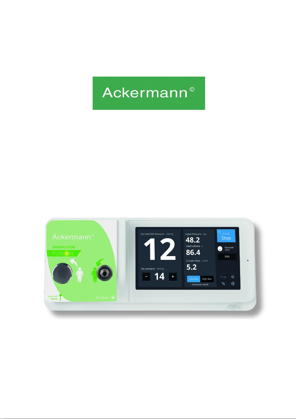
•The insufflator is intended for professional use in operating theatres
•To ensure proper hygiene between patients and avoid contamination, make sure tubes
are thoroughly sterilized
•Do not drop the device. If the device falls, do not reconnect the device but send it back to
your authorised distributor
•Do not move the device when an operation is in progress
•The use of accessories, transducers or cables other than those specified, with the
exception of transducers and cables provided by the manufacturer of the insufflator, can
result in increased emissions or reduced insufflator immunity
No additional multiple-socket outlets or extensioncords must be connected to the EMsystem.
It is advisable to have a second insufflator in the operating theatre so that action can be
taken if the device fails to perform or if a deterioration in performance is noticed.
The use of this device is always contraindicated in cases of intra-abdominal distension,
or when laparoscopy is contraindicated. Kindly refer to the laparoscope user manual for
absolute and relativec ontraindications.
This instrument is contraindicatedfor hysteroscopic insufflation;it should NEVER beused
in cases of intrauterine distension.
Note: the insufflator distension pressure for laparoscopy must never exceed 25 mm Hg.

USER MANUAL 16-2045 Rev. 09/2017
Page 7of 25
WARNINGS
• Metabolic acidosis and resulting cardiac irregularity
Avoid prolonged intra-abdominal pressures above 20 mm of mercury.
• Reduction of respiration with compromised diaphragmatic movement
• Reduction of venous return
• Reduction of cardiac output
• Acidosis
Excessive absorption of CO2 is due to either a too high flow rate or excessive pressure,
or both. The abdomen can be sufficiently distended by a pressure between 10 and 15
mm of mercury. It is rarely necessary to select an abdominal pressure higher than 15 mm
of mercury. At these levels, the extent of intravascular penetration should be low.
Pressures higher than 20 mm of mercury are hardly ever necessary; they will increase
the quantity and the speed of intravascular penetration. Adequate respiration helps to
prevent problems associated with CO2.
• Idiosyncratic reactions
For patients suffering from microdrepanocytic diseases or pulmonary insufficiency, the
use of these devices
can present an increased risk of metabolic imbalance related to the excessive absorption
of CO2.
• Hypothermia
High-flow insufflation allows for a potential risk of hypothermia; therefore we recommend
using a heating
system to keep the patient’s temperature stable.
• Gas flow
Surgical procedures must be carried out with insufflators able to reach flows between 4 to
10 l/min. Insufflators providing lower flow must only be used for diagnostics procedures.
• Gas coagulation system
Some medical devices delivering gas to the interior of the peritoneal cavity during surgical
laparoscopies (gas lasers, for example) may lead to abdominal over-pressurization. If
venous sinuses are formed, triggering an embolism, the use of a secondary gas source
that is far less soluble in the blood than CO2 can cause a rapid rise in intra-abdominal
pressure. We recommend avoiding the use of these coagulation systems during
laparoscopic procedures, as we, the manufacturer could not be held responsible for any
incident associated with their use.
•Bacterial filter
The use of a hydrophobic bacterial filter is essential for preventing cross-contamination with
the patient
The potential equalisation plug located at the back of the Fusion unit can be used to equalize
the grounding potential of the medical device with that of all the devices plugged into the
main power in the environment. Use the shared grounding system in the hospital or the
building.

USER MANUAL 16-2045 Rev. 09/2017
Page 8of 25
Connect the potential equalisation cable to the equipotential socket C7 at the back of the
device.
Devices connecting to the input/output ports must comply with the IEC 60950-1
standard.
4 Regulatory advice
4.1 Compliance
This device is designed and manufactured bya Ackermann proven to have a certified quality
system.
It meets the requirements of European directive 93/42/CEE, on medical devices.
Consequently, it particularly meets the standards of electrical safety (IEC) and
electromagnetic compatibility (EMC) ad hoc.
4.2 Electromagnetic interferences and electrostatic discharge
Although this product complies with EMC standards, it may in very special circumstances
interfere with other devices, or itself be the object of interference from other devices or an
unfavorable electromagnetic environment.
In order to avoid these situations, it is advisable to:
• Ensure of the quality of the electric power system (especially the grounding of all devices
and medical carts.
• Keep the device away from electromagnetic sources (e.g. compressors, motors,
transformers, HF generators, etc.).
4.3 Medical device vigilance
Like any medical device, this device is subject to the stipulations governing medical device
vigilance, and therefore any serious malfunction must be reported to the manufacturer as
quickly and as accurately as possible. For manufacturer contact details, refer to the first
page of the manual.
4.4 End of lifecycle
This device carries the recycling symbol in compliance with European directive 2002/96
CEE on Waste Electrical and Electronic Equipment (DEEE or WEEE). By correctly
disposing of this device you are helping to prevent harmful effects on the environment and
on human health.

USER MANUAL 16-2045 Rev. 09/2017
Page 9of 25
The symbol displayed on the device and on the accompanying documentation
indicates that this product cannot under any circumstances be treatedas household waste.
It must therefore be delivered to a waste collection center for the recycling of electrical and
electronic equipment. In disposing of it, please comply with the waste elimination norms in
effect in the country where it is installed.
For further details on the treatment, recovery and recycling of this device, kindly contact
your nearest distributor who will advise you on the procedure to follow.
5 Installing the device
This medical device is intended for use by a qualified surgeon for endoscopic applications.
No special training is required to install the device. Kindly refer to the instructions in this
manual.
5.1 Installation
Place the device on a stable surface and have on hand the various accessories required
for it to function;
Make sure the area is well ventilated.
Connect the power cord to the mains socket of the device [C3]; Check that the external filter
is properly in place on the CO2 input socket [C6]. This is necessary for the protection of the
internal circuits and will help prolong the life of the insufflator.
5.2 Connecting to a cylinder of medical CO²
Maximum allowed operating pressure (60 bars)
Never begin any surgical operation without having a CO2 replacement cylinder. Only
use medical-grade CO2, in compliance with European standards.
Place the CO2 cylinder in a vertical position, so that it is secure with the upper part
facing upwards, if possible on the same medical cart as the insufflator.
Never use the insufflator connected to a cylinder in a horizontal position or with the
upper part facing downwards.
Use the supplied open-end spanner to tighten the connector attached to the cylinder
outlet, and the connector attached to the external filter on the input port on the insufflator
[C6].
5.3 Connecting to a medical CO² central wall point
Manually connect the low-pressure hose to the wall connector .
Minimum allowed operating pressure: 3 bars.
Only use with the CO2 gas central wall system, in compliance with European standards.

USER MANUAL 16-2045 Rev. 09/2017
Page 10 of 25
5.4 Disconnecting the CO² cylinder
Before unscrewing the high-pressure hose:
- Check that the valve on the cylinder is closed, then:
• Lower the pressure inside the system by slowly unscrewing the tubing hose.
OR
• Use the Purge function (on the interface, tap PURGE) after closing the valve on the bottle.
5.5 Disconnecting from the wall point
Manually disconnect the low-pressure hose from the wall point.
5.6 Connecting to the Ackermann Fusion Camera
Turn off the devices.
Connect the cable supplied with the camera to the socket on the back side of the camera
control unit, and then to the back side of the insufflator [C5].
Turn on the devices.
6 Operating guidelines
This insufflator in only intended for use in diagnostic procedures or laparoscopic operations.
Any use outside of these areas constitutes improper use of the product and the user will
therefore be considered responsible for such use. The manufacturer does not accept any
liability in this case. This device must only be used by qualified staff. The surgeon and
anaesthesiologist shall at all times be responsible for the device and the anaesthesiologist
shall undertake special vigilance of gas levels in the blood. The safety features on this device
are in no way intended to reduce the responsibility of medical staff with respect to constant
attention to the screen and continuous monitoring of the patient.
6.1 Activation
Turn the switch [S2] to position “1”; the device is now in standby mode (the indicator light
on the Standby button [S1] will be flashing, and the Ackermann logo should appear on the
touch screen [L1]);
Press the Standby button [S1] or tap the touch screen to start the device (the indicator light
comes on and the calibration phase, which lasts for a few seconds, starts). Pressing the
Standby button again puts the device back in standby mode.
Note: If the insufflator is connected to the Ackermann Fusion camera, activating the camera
will automatically activate the insufflator and vice-versa. However, the insufflator can be put
in standby mode, or turned on, independently.

USER MANUAL 16-2045 Rev. 09/2017
Page 11 of 25
6.2 Fitting the tubing hose
The manufacturer cannot be deemed responsible for reactions or malfunctions
associated with the use of damaged or inappropriate tubing hoses.
Do not use the tubing hose if its packaging is damaged.
Sterile tubing hoses are disposable; do not re-sterilise them.
The use of a hydrophobic bacterial filter is essential for preventing cross-contamination
between patients. It must be replaced for each patient. Open the first pack of film wrapping on
the tubing hoses. Hand the second one to the staff In a sterile environment.
Keep the sterilised tubing hose for the patient in the operating theatre.
Connect the insufflation part of the tubing hose to the gas outlet on the insufflator [C2] and the
external desufflation part of the tubing hose to the connector [C1] provided for this purpose.
The tubing hose must be free when inserted, without any knots, and must not be
obstructed.
Connect the (sterile) distal end to the patient.
We recommend connecting the patient-end of the tubing hose to a Verres needle in the
first phase. This first phase corresponds to low-flow insufflation (max. 2L/min) until the
pressure setpoint is reached. Once the pressure setpoint has been reached, you can move
on to the second phase consisting of high-flow mode (up to 45L/min) with the patient-end
tubing hose connected to the trocar.
The use of a verres needle is not recommended for high-flow mode.
6.3 Adjusting the pressure setpoint
This operation must be carried out by a surgeon or under the supervision of a surgeon.
This insufflator is equipped with automatic flow rate regulation to attain and maintain a
pressure setpoint, and therefore the pneumoperitoneum
Use the “ + ” and “ - ” buttons to select the pressure desired in the abdominal cavity.
The pressure generally used is 12 mm Hg.
As a precautionary measure, you will be asked to confirm the pressure if you wish to exceed
the 15 mm Hg threshold.
The pressure can be adjusted to a maximum of 20 mm Hg in Standard mode, and to 25 mm
Hg in bariatric mode.
The automatic change-over must be selected on the surgeon’s orders.
Press the “STOP”button to halt insufflation.

USER MANUAL 16-2045 Rev. 09/2017
Page 12 of 25
6.4 Activating / Switching-off insufflation
Press the “RUN” button on the interface menu to start insufflation. A chronometer is displayed
on the screen when insufflation is in progress. The MENU is not accessible when insufflation
is in progress. To access it, insufflation must be halted by tapping on “STOP”.
Insufflation begins in low-flow mode (2 l/min), so that the pneumoperitoneum is created in the
safest of conditions. When the low flow rate is activated, the “low flow rate” is displayed in blue
on the screen.
The high flow rate mode is activated manually by tapping the corresponding sign on the
interface menu or automatically if automatic change-over is activated (in the menu
parameters).
Automatic change-over is used to automatically changefrom low-flow mode to high-flow mode
once the pressure setpoint has been reached. When the high flow rate is activated, “high flow
rate” is displayed in blue.
The automatic change-over must be selected on the surgeon’s orders. Tap on “STOP”
to stop the insufflation.
6.5 Controls
When the pneumoperitoneum has been created at the required pressure, the insufflator will
keep this cavity at the pressure selected and will immediately compensate for any leakage of
CO2.
The high-flow mode must be activated in order to benefit from maximum reactivity from
the insufflator.
When the determined pressure has been reached, the insufflator will stop insufflating.
The insufflator will resume as soon as the pressure in the cavity falls below the pressure
selected.
Control the pressure in the trocar during gas input.
6.6 Excessive pressure
As soon as the instantaneous pressure in the cavity exceeds the pressure setpoint by 2 mm
Hg:
- The message “EXCESSIVE PRESSURE”is displayed on the screen.
The insufflator then opens the external desufflation valve to lower the pressure in the cavity.
As soon as the pressure in the cavity exceeds the pressure setpoint by 5 mm Hg:
- The instantaneous pressure display turns orange
The insufflator then opens the external desufflation valve to lower the pressure in the cavity.

USER MANUAL 16-2045 Rev. 09/2017
Page 13 of 25
6.7 Parameters
The instantaneous flow is shown on the screen in litres/minute.
The volume of gas used is shown in litres on the screen (accurate to the decilitre. For
illustrative purposes only.)
This measurement begins at the same time as insufflation and is only reset to zero when it
reinitializes each time the device is started up (or from the parameters interface menu).
If necessary, set it to zero using the menu.
Only use medical-grade CO2, in accordance with European standards.
6.8 End of operation
Halt insufflation by tapping the “STOP” button. The chronometer stops.
Immediately disconnect the tubing hoses between the trocar and the insufflator to avoid any
liquid or gas backflow into the device.
The tubing hoses used must be discarded after use in an appropriate container.
The total volume of gas insufflated during the operation is displayed; reset the gas counter to
zero if another operation is planned without turning off the device.
Press the Standby button [S1] to put the device in Standby mode. Turn the power switch [S2]
to the “O” position to turn off the device.
7 Special features
7.1 Control from the Ackermann Fusion camera head (Ackermann Fusion
camera only)
The following insufflator functions can be controlled using one of the three programmable
buttons located on the camera head: RUN (in low flow mode), HIGH FLOW RATE, STOP. A
special communication cable must connect the Ackermann Fusion camera to this insufflator
at the dedicated socket [C5] (see Ackermann Fusion camera user manual for further
information on configuring this switch). In addition, this communication cable is for receiving
feedback information (instantaneous pressure in the cavity, warning messages) on the
surgical monitor.
7.2 Autonomous operation with the CO² cylinder
This patented function indicates the insufflation time remaining based on the remaining CO2
capacity in the cylinder. It helps the surgical team to better manage:
- surgical operation time,
- cylinder changes.
The autonomous function is triggered when the pressure of the CO2 cylinder is below 33 bars
and when autonomy is equal to or less than 99 minutes.

USER MANUAL 16-2045 Rev. 09/2017
Page 14 of 25
7.3 Safety
• Preheating system
This warms the gas in the device.
• Automatic test
Automatic calibration of the device and testing of the basic components on each start-up, in
less than one second.
• Detection of tubing hoses
The device will only start if a tubing hose is connected both to the CO2 outlet and the
external desufflation valve (for safety reasons, it is impossible to connect only one of these
elements).
• Automatic flow rate adjustment
This insufflator automatically regulates the flow rate based on the operating conditions in
order to maintain an abdominal pressure equal to the determined pressure.
• An additional pressure sensor
If the measurement circuit is not functioning properly, the consistency of the measurements
is constantly monitored; this means that the insufflation cycles can be interrupted if there is
the slightest doubt.
• High-pressure discharge valve
If excessive pressure is created in the high-pressure regulator, a safety valve is available to
limit the risks.
• Bacterial filter
This filter limits the risk of cross-contamination between patients.
7.4 Low flow rate
In this mode, the insufflation flow rate is limited to 2 l/min to create the pneumoperitoneum.
This flow rate is not sufficient to regulate the pressure inside the cavity in the event of
substantial escape of gas and it will therefore be necessary to change to the high flow rate.
By default, the insufflator starts in low flow mode. The surgeon can choose between manual
and automatic mode to activate the high flow rate.

USER MANUAL 16-2045 Rev. 09/2017
Page 15 of 25
7.5 High flow rate
When the pneumoperitoneum is created, activating this mode enables a maximum flow rate
of up to 45 L/min to be reached. This capacity is then used to compensate for all types of
leakage. It is advisable not to use verres needles in this mode.
7.6 Automatic High/Low flow rate
If the automatic change-over switch is set to “ON” in the settings, the device begins to insufflate
in low-flow mode, and then changes to high-flow mode once the pressure setpoint has been
established in the cavity.
7.7 External desufflation valve [C1]
Our insufflators are equipped with a valve for releasing excess CO2 pressure from the device
so as to avoid:
•Excessive pressure in the pneumoperitoneum
•Any backflow of fluid inside the device, and in this way avoid any risk of deterioration or
contamination.
7.8 Testing of medical CO² cylinder pressure
This latest generation of insufflators is equipped with a pressure measurement system in the
cylinder with continuous visibility.
When the pressure in the CO2 cylinder reaches 40 bars, the corresponding logo is displayed
in orange. When the pressure in the CO2 cylinder reaches 20 bars, the corresponding value
is displayed in orange.
Below a pressure of 10 bars, the insufflator cannot start. The display of the input pressure
value changes to orange.
7.9 Testing of medical CO² central wall point
This latest generation of insufflators is equipped with a CO2 gas central wall point pressure
measurement system with continuous visibility. Below a pressure of 2.8 bars, the insufflator
cannot start. The display of the flow rate input value changes to orange.
From 10 bars, the insufflators will change automatically to “cylinder” mode. Only to be used
with a medical CO2 gas central wall point, in compliance with European standards.

USER MANUAL 16-2045 Rev. 09/2017
Page 16 of 25
7.10 Touch screen [L1]
For better communication and for easier use, we have equipped our latest generation of
insufflators with a user-friendly touch screen. This serves to provide the following information:
• warnings and error messages
• indications that the cylinder is empty
• indications of the instantaneous pressure in mm Hg
• indications of the pressure setpoint in mm Hg
• indications of the flow rate in l/min
• indications of the volume of CO2 used in litres
• status indications: on / off and “high flow rate” / “low flow rate”
• indications of the operating mode
7.11 CO² central wall point and CO² cylinder capacity on the same
device
This device can be connected to the CO2 system between 3 and up to 5 bars and to medical
CO2 cylinders. In the MENU, simply select “WALL POINT” or “CYLINDER”.
7.12 Pure function
If a CO2 cylinder is connected, the interface “Purge” button can be used to purge the high-
pressure hose before disconnecting it from the cylinder. To do so, remove the tubing hose
from the insufflator, close off the CO2 cylinder and press the “Purge” button.
7.13 Hose obstruction messages
A message is displayed on the screen when the insufflator detects a tubing hose obstruction.
7.14 Operating modes
This insufflator cannot work in two modes with differing maximum value settings for the
pressure setpoint.
The standard mode allows a maximum pressure setpoint value of 20 mm Hg. The bariatric
mode allows a maximum pressure setpoint value of 25 mm Hg.

USER MANUAL 16-2045 Rev. 09/2017
Page 17 of 25
8 Suggested decontamination procedures
The insufflator is a medical device, not heat resistant and it cannot withstand immersion;
consequently it should be disinfected with a non-woven medium saturated disinfectant
detergent.
Decontamination methods and/or selected tools, it remains under the full responsibility
of the staff concerned.
This device cannot be autoclaved.
Existing alkaline solutions for the disinfection of certain medical devices are NOT
RECOMMENDED for the disinfection of this device.
Always disconnect the device before cleaning it.
After each use:
Discard disposable sterilized tubing hoses; do not attempt to re-sterilse them.
Clean up all possible spatters on the insufflator by removing them with a slightly
moistened cloth.
The device must always be decontaminated before sending it back to the manufacturer
or distributor.
9 After-sales service and maintenance
No particular maintenance operation is needed for this device.
Note: misuse is not covered by the warranty. If a fault persists and the device has to be
returned to the distributor, ensure that it is shipped in its original packaging.
Similarly, it is advisable to return the device in its entirely (control unit and power cables).
Kindly attach to the shipping order a short explanatory note about the fault detected.
The equipment must be disinfected before returning for repair. When returning the
equipment, check its condition and make notes on the delivery note if necessary, confirming
them with the carrier by registered letter as soon as possible.
Please contact your distributor who will guide you through the return process.

USER MANUAL 16-2045 Rev. 09/2017
Page 18 of 25
10 Troubleshooting
Warning
Possible Cause
Measures to take
Orange cylinder logo
Cylinder pressure at 40 bars
Change the cylinder. it is
advisable to prepare a
replacement cylinder as soon
as the cylinder pressure
reaches 40 bars.
gas cylinder valve closed
Open the valve
high-pressure hose connector
on the insufflator disconnected
Turn off the device, check that
the CO2 gas is flowing and turn
the device back on
Excessive pressure
sporadic action on the
pneumoperitoneum
none.
- if the pressure exceeds the
pressure set by 2 mm hg, the
device will create mild
exsufflation.
Tubing hose tangled
stretch out the tubing hose
Trocar valve closed during
insufflation
Open the trocar
Chck the tubing hose
Tubing hose missing
Connect the tubing hose
The tubing hose is not correctly
connected
Correctly connect the tubing
hose to [C1] and [C2]
Tubing hose fault detected
Sent the device to the
distributor for repair
Tubing hose obstructed
Bent tubing hose
stretch out the tubing hose
Trocar valve closed during
insufflation
Open trocar valve
CO2 not detected
gas cylinder valve closed
Open the valve
high-pressure cylinder or
insufflator hose disconnected
Correctly connect the hose to
the insufflator and to the
cylinder
CO2 gas wall point system
faulty
Check whether the pressure
supplied by the CO2 gas wall
point system is higher than 3
bars.
insufflator hose connection /
wall point system connection
Carefully connect the hose to
the CO2 gas wall point outlet
and to the insufflator

USER MANUAL 16-2045 Rev. 09/2017
Page 19 of 25
Note:
If the insufflator does not switch on, this could be due to damage to the fuses. If so, it is
advisable to turn off the power, check and if necessary replace the fuses (use only T25AL –
250 V delayed-action UR fuses)
For any other problems, contact your nearest after-sales service department.
11 Technical characteristics
Pneumatics:
•CO2 gas supply system: US 7/16˝connector
•Pressure range:
- CO2 cylinder: 10 to 60 bars
- central gas wall point outlet: 3 to 5 bars.
•Maximum flow rate
- 45 l/min in high-flow mode
- 2 l/min in low-flow mode
•Pressure setting: 0 to 25 mm Hg (accuracy: 1 mm Hg)
•External exsufflation valve
•Automatic low-flow / high-flow function selection option
Interface:
•Touch screen displaying: immediate flow rate, pressure in the cavity, total volume
of CO2
used and low cylinder levels
Energy supply:
•Types of energy: 100 - 230 V AC 50 - 60 Hz
•Fused protection: 2 x 2.5 AT - 250 V delayed-action UR fuses
•Power consumption: 75 VA
Mechanics:
•Dimensions (W x H x D): 310 x 136 x 385 mm
•Weight: 8000g
Operation - transport and storage environment:
•Operating temperatures between + 10 ºC and + 40 ºC
•Operating relative humidity between 30 and 75 %
•Transport and storage temperatures between - 10 ºC and + 45 ºC
•Transport and storage relative humidity between 20 and 85 %
•Operating, transport and storage atmospheric pressure between 700 hPa and
1060 hPa

USER MANUAL 16-2045 Rev. 09/2017
Page 20 of 25
Standards:
•Electrical protection: class 1, type CF
•Compliant with standard IEC 60 601-1; with variants for the United States and
Canada
•No protection against water (IPXO)
•Not suitable for use in the presence of a flammable anaesthetic mixture, air,
oxygen or nitrous oxide
12 Electromagnetic compatibility
12-1 Manufacturer’s guide and declaration – electromagnetic emissions
This insufflator was designed to be used in the electromagnetic environment specified below.
The user must ensure that it is in fact used in this environment.
Emission test
Compliance
electromagnetic environment - guide
RF emissions CisPR 11
group 1
This insufflator only uses radio energy for its
sub-systems. it therefore emits very weak RF
energy and is not likely to interfere with nearby
electronic devices.
RF emissions CisPR 11
Class A
This device must be used on premises
other than domestic premises and premises
directly connected to low-voltage
public electric power systems providing power
to buildings for domestic purposes.
Harmonic emissions en 61000-3-2
Class A
Variations in voltage/
flashing EN 61000-3-3
Compliant
This manual suits for next models
1
Table of contents
Other ACKERMANN Medical Equipment manuals