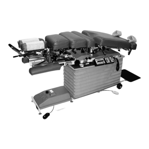
Lloyd COSMIC III User manual


CONTENTS
OPERATIONS PAGE
Safety and Maintenance..................................................................1 - 2
Setup Instructions............................................................................3
Electrical Connection.......................................................................4
Operating Instructions & Functions of the Controls.........................5 - 6
Calibration Instructions.................................................................... 7
Product Disclaimer...........................................................................8
Table Specifications......................................................................... 8
Assisting Patients On & Off Table........... ........................................ 9
Cabinet Assembly............................................................................ 10
Roller Carriage Assembly................................................................ 11
Travel Carriage Assembly................................................................12
Electrical Assembly.......................................................................... 13
Cosmic III Wiring Diagram...............................................................14
Hand Held Control Diagram............................................................ 15
Table Serial Number

WELCOME!!
Lloyd Table Company, a proud supporter of today’s chiropractors, has established the finest line of
chiropractic tables in the world. Table products unique in versatility and function, designed to meet
your needs.
Concerned for a safe working and treatment environment, Lloyd Table Company asks that you follow
the safety tips below.
*Read all instructions in the operations manual thoroughly before operating your
Cosmic III inter-segmental traction table.
*Only a qualified and trained health care provider should use the Cosmic III.
*Instruct patient on proper mounting and dismounting of the table.
*A patient should never be unattended, when lying on the table.
*Patients should not be allowed to sit on the table unless a qualified staff member
supervises them.
*Do not allow children to play around the table.
*Always unplug the table before removing the tabletop.
*Never place hands or fingers in front of or behind the rollers.
*Follow the maintenance schedule provided in this Operation’s Manual.
SAFETY
Page 1

MAINTENANCE
The following list covers all areas of the Cosmic III Inter-segmental Traction Table that should be
checked, cleaned and have worn parts replaced during a preventative maintenance. Maintenance
schedules are listed below and it is suggested that a maintenance routine every six (6) months
should be performed by a qualified service technician.
*Always unplug table before doing maintenance.
*Clean and wipe off any dust accumulation inside the cabinet along with all parts.
*Blow dust from relay board when cleaning (see Fig. 2 Page 3)
*Inspect rollers to see that they are turning smoothly and quietly.
*Check the drive chain to see that it is taut.
*Check switches for proper operation.
Upholstery Care and Cleaning
For proper care and cleaning of the upholstery material, use a solution of 10% household
liquid dish soap with warm water applied with a soft damp cloth only.
Use of cleaners not specifically recommended for vinyl or lack of care and cleaning of the
upholstery may result in the vinyl becoming hard and brittle.
Page 2

Read and complete all steps of instructions before operating your Cosmic III table.
1. Remove Cosmic III from crate
2. Remove the tabletop from the base of the table,
by simply lifting the strap on top.
3. Remove Contents-Bag (Hand Control, A/C
Cord,and Wheels).
4. Install wheels (See Fig. 1).
SETUP INSTRUCTION
5. Install Hand Control (See Fig. 2).
Page 3
Fig. 1
Fig. 2
A. Simply feed the cable of the Hand Held Unit through the base of the table as shown in Fig. 2.
B. Connect the Cable of the Hand Held Unit to the five prong male connector as shown above in
Fig. 2.

6. Mount Hand Control Cradle to side of table or on wall.
7. Plug in A/C cord to back or foot end panel (See Fig. 4)
8. Plug A/C cord into Grounded wall outlet.
9. Turn table on by pressing the master power switch (See Fig. 4)
10. Once the master power is tuned on, the massage rollers will automatically lower.
As the massage roller lowers, a brace used to secure for shipping will drop onto
rollers. Please remove and discard the brace.
11. Replace the tabletop and check all functions before use on patient.
Page 4
ELECTRICAL CONNECTION
A power supply of 120 volts, 60Hz AC, 10 amps are required. For your personal safety, this
insturment must be grounded. This device is equipped with a power supply having a three (3) prong
grounding plug. To minimize possible shock hazard, it must be plugged into a mating three (3)
prong grounding type wall receptacles, grounded in accordance with the National Electrical Code
and local codes and ordinances. If a mating wall receptacle is not available, it is the responsibility
and obligation of the customer to have properly grounded three (3) prong wall receptacle installed by
a qualified electrician.
WARNING!
*RISK OF FIRE, ELECTRICAL SHOCK AND PERSONAL INJURY HAZARD.
* AN EXTENSION CORD SHOULD NOT BE USED WITH THIS INSTURMENT.
*DO NOT, UNDER ANY CIRCUMSTANCES, REMOVE THE POWER SUPPLY
CORD GROUND PLUG!
Fig. 4
Master Power
Switch

Adjusts Treatment
Parameters
Page 5
Before operating this machine the operator should first become familiar with the purpose and the
functions of the Cosmic III.
OPERATING INSTRUCTIONS
PURPOSE OF UNIT
The Cosmic III is for spinal inter-segmental traction, spinal mobilization, and back massage. The
table was designed to apply controlled pressure through the action of three rotating rollers that can
be placed either in a stationary position or in longitudinal motion (TRAVEL). Changing the height of
the rollers varies the pressure. The direction in which the rollers rotate is adjustable.
FUNCTIONS OF THE CONTROLS
Before operating functions of the Cosmic III, the table must first be plugged into a three
prong-grounding receptacle.
The hand held control consists of the following switches:
Starts / Pauses
Treatment
Massage Roller
Direction
Massage Roller
Height
Toggles Massage
Roller Carriage
ON/OFF
Toggles Vibration
ON/OFF
Stops All &
Retracts Massage
Rollers
Time
Direction
Height

FACTORY PRESET PROGRAM
The Cosmic III is factory set with the following parameters:
1. The treatment time is preset for 10 minutes.
2. The direction of the massage rollers is rotating toward the foot (F) end of the table.
3. The massage roller carriage “TRAVEL” is turned on.
A treatment session, with the above parameters, will start once the “TIME” button is pushed. By
default the massage roller height is at the lowest setting, thus you must push and hold the
“ADJUST” up button to raise the massage rollers to the desired height.
DURING THE TREATMENT
The treatment can be paused by pushing the “TIME” button once. To restart and continue the treat-
ment push the “TIME” button once again.
To start the vibration feature simply push the “VIBRATE” button once. To turn off vibration feature
simply push the “VIBRATE” button again.
You can stop the travel of the massage roller carriage, to work in a specific area, by pushing the
“TRAVEL” button once. To resume massage roller carriage travel push the “TRAVEL” button once
again.
By pushing the “STOP” button all treatment parameters will stop and the massage rollers wil lower
to the lowest setting.
Page 6
If you wish to set your own treatment parameters please use the following directions:
1. Press and hold the “STOP” button for at least 5 seconds. The display will start flashing
ON/OFF showing that the unit is in the program mode.
2. The program mode is entered with the session time ready to set. Press the adjust up
button or down button to change session duration.
3. Press the “DIRECTION” button and then push the “ADJUST” up button twice for Head
(H) or “ADJUST” up once for Neutral (--). NOTE: By Default the directionof rotation of the
massage rollers is in the (F) position.
4. To end programming, press and hold the “STOP” button for at least 5 seconds.
The display will stop flashing and the unit will operate as programmed.
CUSTOMIZE TREATMENT PARAMETERS

Calibration Instructions
The Cosmic III includes a miro-controller that is used to calibrate the height settings.
This procedure describes how to power up the bench the first time it is used and how to calibrate
the height settings.
1. Check that the frame of the carriage and frame of the travel motor have continuity to the ground
pin of the line cord.
2. Check to be sure the fuse wire is connected to the switched terminal of the power entry module.
3. Check the fuse is 6-1/4 Ampere.
4. Observe that the potentiometer and hand controller are plugged in the circuit board (shown
above) check the wiring to make sure it is correct.
5. Set the ON/OFF switch to OFF and plug the line cord into the power outlet (wall socket).
6. Set the ON/OFF switch ON and observe the handheld display digits light and temporarily display
“88”.
7. In short time the display should change to read “E3” if this is the first time the electronics have
been used.
8. Push the calibration button (shown above) on the curcuit board. This is a small button near the
upper right hand corner of the board (shown above).
9. Push and release the Height button (shown on page 6). At this time the message head height
should run all the way to the maximum height and then return back to minimum. When the
height has returned to minimum, the calibration is complete.
10. If the table controls lock up or display does not make sense, turn off the power and wait at least
twelve seconds before turning power on again.
!! NOTE !!
Your Cosmic III has already been calibrated at the factory. The following procedures are to be carried out by a qualified
service representative & only if you recieve a “E-3” messa ge on the control head.
Page 7
Calibration
Button
Hand
Controller
Plug-in
Potentiometer
Plug-in

Page 8
CONTRAINDICATION
Contraindication of localized inter-segmental traction are:
1. Skin irritations that might be aggravated by the rollers, such as:
* Shingles
* Sunburn
* Boils
* Bruises
2. Phlebitis: (inflammation of a vein).
3. Fractures of a bone or suspected fractures.
Lloyd Table Company does not represent or warrant under any circumstances that a particular result
can or will be achieved by using this product. The choice to use the product, the method or methods
of use, the diagnosis of the patient’s condition and application for the patient is solely the
responsibility of the treating physician and not Lloyd Table Company
DISCLAIMER
Height: 25 inches
Length: 72.5 inches
Width: 22 inches
Shipping Weight (approx): 175 lbs.
Table Weight: 118 lbs.
TABLE SPECIFICATIONS

* The doctor or trained staff should always place the patient on the table. Do NOT allow the
patient to get on the table without help. This could cause strain to the patent or a loss of
balance. Also, assistance is needed so that the patient does not put pressure on the roller area
of the table with his or her arm.
* The patient should check clothing for keys, wallet, or any other items that may cause discomfort
from the rollers during the treatment.
* To be assured that discomfort or strain does not come to the patient while being helped on to the
table, the pressure rollers should be in the lower position. (The table automatically has this feature
unless a malfunction exists)
* Position the patient on the unit so that the base of the spinal column (sacrum) is located at the
end of the roller-slot. Change the position of the patient ONLY if a specific treatment for the spinal
column is suggested.
* Keep the lights dim and avoid bright lights glaring into the patient’ eyes.
ASSISTING PATIENTS ON THE TABLE
ASSISTING PATIENTS OFF THE TABLE
Caution the patient not to get up from the table alone, so as to prevent a strain that may cause a
chance of becoming lightheaded which can develop from laying down and cause loss of balance.
SEVEN EASY STEPS TO HELPING PATIENTS OFF TABLE:
1. Brace your knee against the table.
2. Extend your left forearm across patients’ chest and have patient grasp your arm near
the elbow.
3. Have patient hold your arm and not apply any strain to sit upright.
4. Put your right hand under the patients’ left knee.
5. As patient pulls on your arm, pivot the patient on the buttocks by pulling on the left
knee and gently swing the legs off the table.
6. The patient quickly and easily comes to a sitting position.
7. Allow patient to regain balance before coming to full standing position.
Page 9

COSMIC CABINET ASSEMBLY
1
2
2
8
3
4
5
6
7
9
9
16
10
11
12
13
14
15
16
ITEM PART N0. DESCRIPTION QTY.
1 43125 TOP ASS’Y 1
2 43101 SIDE ASS’Y 2
3 43118 BACK END ASS’Y 1
4 43117 SUPPORT RAIL 4
5 56485 GUIDE RIAL 2
6 43121 CROSS BRACE 1
7 43120 ELECTRICAL PLATFORM 1
8 43123 FRONT END PANEL ASS’Y 1
9 22486 FLAT HD. SHEET ROCK SCREW, #8 X 1 5/8 10
10 20010 HEX.HD. BOLT, ¼-20 X ¾ 16
11 21610 FLAT WASHER, 1/4 16
12 24411 PLASTIC CAP 4
13 24439 WHEEL CASTER 4
14 24268 INSERT 4
15 56454 END FRAME ASS’Y 2
16 22484 FLATE HD. SHEET ROCK SCREW, #8 X 1 1/4 14
Page 10

Page 11
2
6
3
3
5
7
8
9
22
18
21
21
13
22
14
4
15
10
16
17
11
23
12
22
22
22
10
17
ITEM PART N0. DESCRIPTION QTY.
1 56475 ROLLER CARRIAGE ASS’Y 1
2 56450 ROLLER STAR ASS’Y 1
3 56113 WHEEL 6
4 22690 CLEVIS PIN, 3/8 RD X 1 ¾ 1
5 22640 COTTER PIN 6
6 56489 AXLE ROD 3
7 20220 HEX HD. BOLT, 5/16-18UNC X 1 2
8 21710 FLAT WASHER, 5/16ID X .688OD 4
9 22810 BALL BEARING 2
10 20810 HEX NUT, NYLON LOCK, 5/16-18UNC 2
11 24398 SPROCKET, 5/8 ID-9 TOOTH 1
12 20023 HEX HEAD BOLT, ¼-20UNC X 1 1/4 2
13 22692 CLEVIS PIN, 3/8 RD X 3 ½ 1
14 22639 COTTER PIN, 3/32 X ½ 1
15 56464 TENSION PLATE 1
16 20222 HEX HEAD BOLT, 5/16-18 UNC X 1 ¼ 1
17 20022 HEX HEAD BOLT, ¼-20 UNC X 1.00 4
18 55906 DRIVE CHAIN #40 1
19 21640 FENDER WASHER, 1/4 ID 2
20 22912 SET COLLAR, 3/8 ID 1
21 20800 HEX NUT NYLON LOCK, ¼-20UNC 6
22 21610 FLAT WASHER 1/4” ID X 1/2” OD 10
23 24208 CONNECTING LINK 1
1
19
ROLLER CARRIAGE ASSEMBLY

Page 12
TRAVEL CARRIAGE ASSEMBLY
4
8
79
7
2
3
13
12
8
11
4
26
20 17 6
18
16
5
8
11
21
14
15
19
22
23
24
25 27
1
28
29
30
33
31
32
34
6
3
3
35
10
ITEM PART N0. DESCRIPTION QTY.
1 56465 TRAVEL CARRIAGE FRAME 1
2 24437 RUBBER WHEEL 2” 4
3 21620 FLAT WASHER, 1/4ID X 9/16OD 8
4 20022 HEX BOLT, 1/4-20UNC X 1.00 8
5 20002 SHLD BOLT, ¼-20UNC X 3/8 1
6 20795 HEX NUT, #10-24 UNC (NYLON) 1
7 22818 BALL BEARING, ROLLER CARRIAGE 2
8 21710 FLAT WASHER, 5/16ID X 5/8OD 8
9 20220 HEX BOLT, 5/16-18UNC X 1.00 4
10 20799 HEX NUT, NYLON INSERT, #8-32 UNC 2
11 20810 NYLON LOCK NUT, 5/16-18UNC 4
12 21760 PLASTIC WASHER, 5/16ID X ½OD 2
13 56488 LINKAGE BAR 1
14 56461 AXLE, IDLER 1
15 56463 MOUNTING PLATE 1
16 24398 SPROCKET, 9 TOOTH 1
17 22910 SET COLLAR, ¼ ID 1
18 20023 HEX BOLT, ¼-20UNC X 1 ¼ 1
19 56458 TENSION BLOCK 1
20 24207 TRAVEL LINK 1
21 55905 DRIVE CHAIN 49 ½” 1
22 22830 ROLLER BEARING 5/8” 2
23 21214 HEX NUT, 5/8-18 UNF 1
24 20007 HEX BOLT ¼-20UNC X 5/8 2
25 20320 HEX BOLT, 3/8-16 UNC X 3/4 2
26 56449 ADJUSTING ROD 3/8-16UNC 1
27 21210 HEX NUT, 3/8-16UNC 1
28 56484 SWITCH MOUNTING PLATE 1
29 21968 FLAT HD SCREW, #3MM X .5 X 6 2
30 21985 PAN HD SCREW, #8-32unc x 3/4 2
31 22909 SET COLLAR 3/16 ID 1
32 22000 OVAL HD SCREW, #10-24 UNC X ¾ 1
33 56490 LINKAGE BAR, 1/8 X 3/4 X 10 1/8 1
34 22860 BUSHING, 3/16 ID X ¼ 0D 1
35 22940 SET COLLAR, 5/8 ID 1
36 21810 3/8 ID FLAT WASHER 2
36
4
3
3

ELECTRICAL ASSEMBLY
Page 13
ITEM PART N0. DESCRIPTION QTY.
1 30590 ROTATION MOTOR 1
2 30516 VIBRATION MOTOR 1
3 35215 MOTOR BRACKET 1
4 44961 POTENTIOMETER SWITCH ASS’Y 1
5 37940 SPACER, CIRCUIT BOARD 4
6 30591 HEIGHT MOTER 1
7 45205 CABLE ASS’Y, HEIGHT MOTOR 1
8 31508 CIRCUIT BOARD 1
9 38347 WIRE TERMINAL (3 POSITION) 1
10 36510 FUSE HOLDER 1
11 36172 POWER CORD 1
12 37189 SWITCH, AC INLET 1
13 36162 CONNECTOR, QUICK 5
14 38570 WIRE, 18 ga. – 15” 3
15 36360 FUSE 1
16 30589 DRIVE MOTOR 1
17 44949 HAND CONTROL BOX 1
18 35213 HANGER 1
19 22455 WOOD SCREW, #8 x 3/4 2
20 21976 PAN HD. MACHINE SCREW #6-32 unc x 3/4 2
21 38363 WIRE TERMINAL ( 12 POSITION) 1
22 38540 VARISTER 2
23 38570 WIRE, 18 ga. – 54” 9
24 38400 CABLE TIE 10
25 35940 WIRE CLIP 1
26 22420 PAN HD SCREW, #6 x 1.00 4
1
2
3
4
5
23 24
22
21
20
18
19
6
7
12 13 14
11
17
16
10
15
9
8
26

COSMIC III WIRING DIAGRAM
Page 14

HAND HELD CONTROL DIAGRAM
Page 15

Table of contents
Other Lloyd Medical Equipment manuals
Popular Medical Equipment manuals by other brands

Akces-Med
Akces-Med NOOK Use and Maintenance Instruction

Contec
Contec CMS8000 Service manual

B-K Medical
B-K Medical Pro Focus 2202 user guide

3D Histech
3D Histech Pannoramic SCAN 150 1.18 user guide

Etac
Etac Immedia EasyTurn Instructions for use

ARJO HUNTLEIGH
ARJO HUNTLEIGH ENTERPRISE 9000X Instructions for use

Etac
Etac Swift Commode manual

Hillrom
Hillrom Welch Allyn Spot Vital Signs 4400 Assembly instructions

B. Braun
B. Braun Aesculap activ L 011458 Instructions for use/Technical description

Knape&Vogt
Knape&Vogt Easy Corner Instructions for installing

I-care
I-care Icare HOME TA022 Patient guide

Medel
Medel FM user guide