Ackermann
Page: 9 // 28
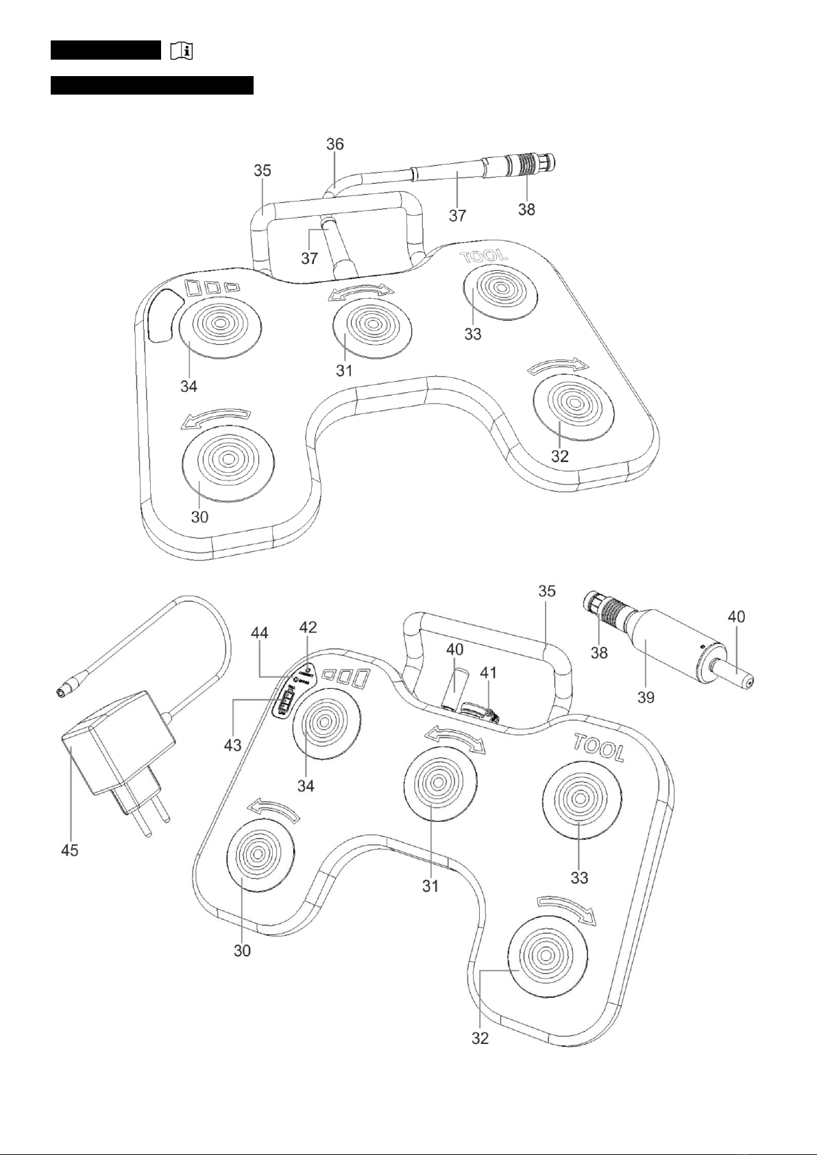
:pedalbuttontoswitchtheshaverbladeintheHandpiecetoanti-clockwiserotation.Thenumberofrotations
dependsonthesetspeedwhichcanbeadjustedviatheUnitControlbuttons(8)and(9)orFootswitchbutton(34).
:pedalbuttontoswitchtooscillatingmode.Thenumberofrotationsdependsonthesetspeedwhich
canbeadjustedviatheControlUnitbuttons(8)and(9)orFootswitchbutton(34).Theoscillationfrequencydependson
settings.
32. FWD:pedalbuttontoswitchtheshaverbladeintheHandpiecetoclockwiserotation.Thenumberofrotationsdepends
onthesetspeedwhichcanbeadjustedviatheControlUnitbuttons(8)and(9)orFootswitchbutton(34).
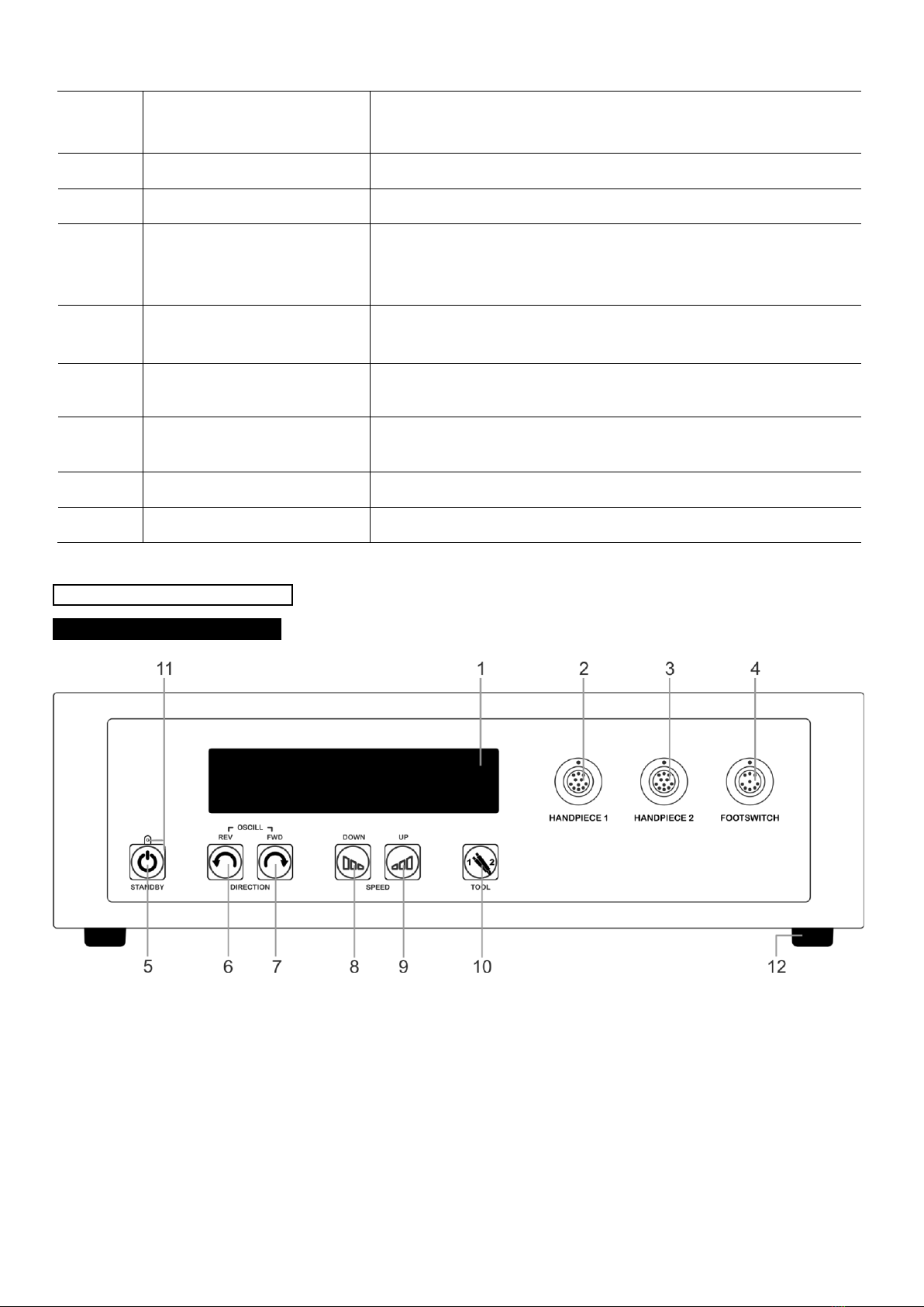
33. TOOL: pedal button to initiate the change function of the steerable device “HANDPIECE 1” (2), “HANDPIECE 2” (3)
connected to the Control Unit.
:pedalbuttontoregulatethespeedoftheshaverbladeintheHandpieceduringuse.Eachtimethebuttonis
pressed,thespeedisincreasedtothenexthigherlevel.
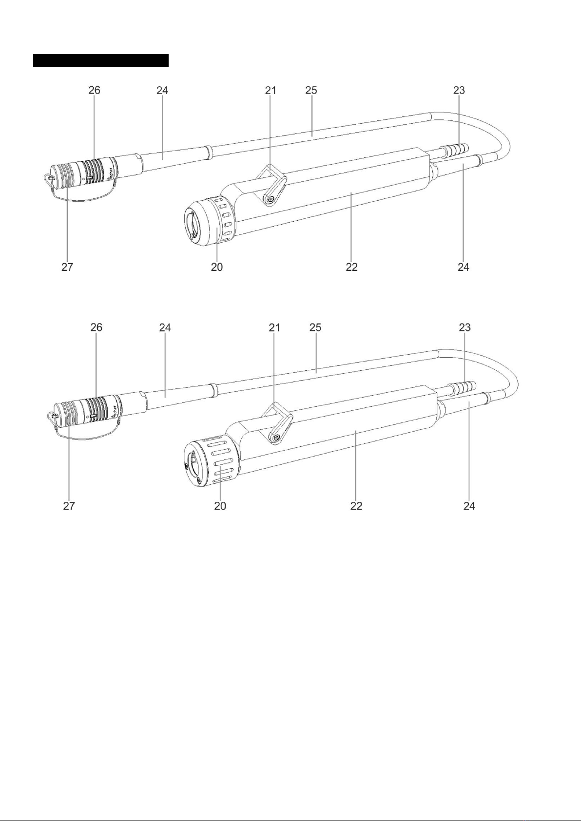
35. Handle: used for lifting and carrying of the Footswitch.
: connection between the Footswitch and the Control Unit, serves to transmit the selected functions of the
individualFootswitchbuttons(30-34).
37. Protective cap: for increased stability of the connection and protection against fracture.
: connection to attach the Footswitch to the Control Unit. An integrated lock at the plug protects the cable of the
Footswitch from being pulled out by accident.
: as a part of the Footswitch serves to transmit information from the Footswitch to the Control Unit, with
which is connected electrically.
: necessary for communication between the Footswitch console and the receiver attached to the Control
Unit.
:usedtoconnectthecharger(45).Chargingshouldbedone outside ofthetreatmentroom. While
charging, functions of the Footswitch are disabled.
:ashingonbluediodesignalsthepropercommunicationbetweentheFootswitchconsoleandthe
receiver(39).
: lighting on green, shows the accumulator level.
: lighting on red diode signals the incorrect charger connection or not compatible charger connection.
: dedicated to charge the accumulator of the Footswitch. Should be used only outside the operating
room.
Thischapterdescribesthecorrectinstallationandstart-upofthedevice.Therststepisthecorrectinstallationofthe
ControlUnit.Thelanguageselectfeatureallowstheoperatortoselectthelanguageofhischoice.Ifthesubsequentsteps
described in chapters 4.1. to 4.6. have been followed correctly, the device is now ready for use and the shaver blades can
be attached.
When the Shaver System Set is not in active use, protect the device against inadvertent actuation of the
Footswitch and the Handpiece!
Beforeinstallation,makesurethatthedevicehassucientventilationbymaintainingaminimumdistanceof10cmfrom
the right, left and rear sides of the device.
Device installation:
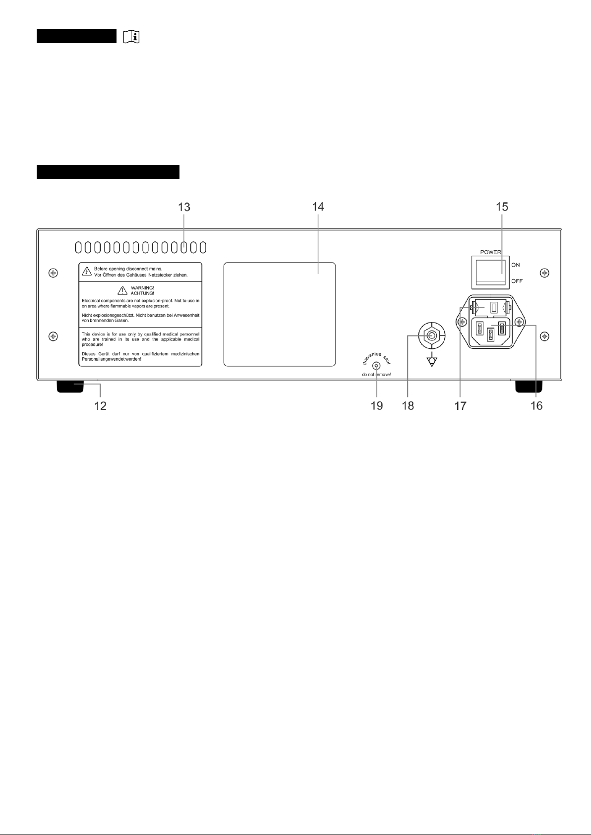
•theonlyintendedpositionoftheControlUnitishorizontal,inwhichthedeviceisplacedonaatsurfaceonitsfourrubber
feet(12).Inaddition,adequateventilationaroundtheControlUnitmustbeprovided,
•theplaceofinstallationshouldbeaat,dryandcleansurface.Thiscanbeatable,shelfofanendoscopytrolleyorother
elements meant for installation of medical devices.
Connecting the device to power:
•connect,usinganappropriatelead,theequipotentialboltlocatedontherearoftheControlUnittoanequipotentialstrip.
Thecableinsulationshouldbeyellow-green,