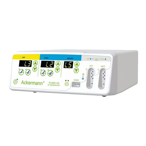
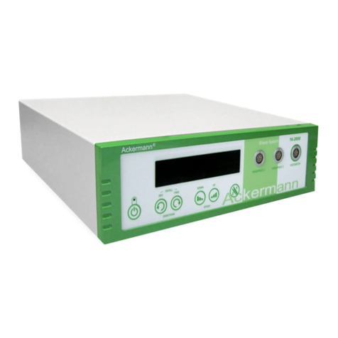
ACKERMANN 16-2000-700 User manual

USER MANUAL 16-2000-700/701/702/703 Rev. 05/2018
16-2000-700/701/702/703
ELECTROSURGICAL UNIT
INSTRUCTIONS FOR USE

USER MANUAL 16-2000-700/701/702/703 Rev. 05/2018
These operating instructions contain information that is subject to copyright.
All rights are reserved.
This manual should not be photo-copied, duplicated on microfilm or otherwise copied or distributed,
completely or in part, without the approval of the manufacturer. The manufacturer will appreciate any
errors or anything unclear in this operating manual being pointed out to us by users of our products.
Due to the continuing progress and development of our products, we reserve all rights for technical
alterations.
Rev. 05/2018
SERVICE ADDRESS:
Ackermann Instrumente mbH
Eisenbahnstrase 65-67
78604 Rietheim-Weilheim
ermany
SYMBOLS USED IN THIS MANUAL:
Impo tant notice
Recommendation
Caution
Wa ning
Page: 2 of 134

USER MANUAL 16-2000-700/701/702/703 Rev. 05/2018
Contents
1. Areas of use for the HF 16-2000-700 syste .........................................................5
1.1 HF 16-2000-700 operating odes...................................................................5
2. Electrosurgery basics..........................................................................................6
2.1 Monopolar operation......................................................................................7
2.2 Bipolar operation..........................................................................................7
3. Sy bol..............................................................................................................8
4. Device appearance and construction.....................................................................9
4.1 Front panel..................................................................................................9
4.2 Back panel.................................................................................................12
4.3 Main panel.................................................................................................13
4.4 Active panel – detailed view for a given output...............................................15
5. HF 16-2000-700 technical specifications..............................................................16
6. HF 16-2000-700 accessories list.........................................................................19
7. Preparing the syste for work............................................................................20
7.1 Connecting power cables..............................................................................20
7.2 Pneu atic ducts connection..........................................................................23
7.3 Connecting accessories for electrosurgical procedures......................................25
7.3.1 Neutral electrode cable.......................................................................25
7.3.2 Instru ent cable for universal ASD sockets...........................................26
7.3.3 Monopolar electrode cable with 3-pin plug.............................................26
7.3.4 Bipolar instru ent cable for 2-pin sockets.............................................26
7.3.5 Argon duct........................................................................................27
7.4 Instru ent detection...................................................................................27
7.5 Wireless footswitch receiver..........................................................................29
7.5.1 Operation with 3-button footswitch.......................................................30
7.6 Settings.....................................................................................................30
7.6.1 Working para eter adjust ent............................................................32
7.6.2 Effect adjust ent...............................................................................33
7.6.3 Argon flow settings.............................................................................34
7.6.3.1 Cautions for using argon-enhanced coagulation...............................36
7.6.3.2 Suggested settings......................................................................37
8. Syste operation and surgical procedures...........................................................39
8.1 Turning the syste on.................................................................................39
8.2 Neutral electrode onitoring – the NEM SYSTEM.............................................39
8.2.1 Monitoring of application of split disposable neutral electrodes.................39
8.2.2 Split disposable electrodes..................................................................42
8.2.3 Non-split reusable electrodes...............................................................42
8.2.4 Neutral electrode application principles.................................................44
8.3 Operating ode selection.............................................................................46
8.4 HF 16-2000-700 syste activation ethods...................................................50
8.4.1 Activation fro handle........................................................................50
8.4.2 Activation fro footswitch:..................................................................50
Page: 3 of 134

USER MANUAL 16-2000-700/701/702/703 Rev. 05/2018
8.4.3 Syste activation using the AutoStart function......................................51
8.5 Monopolar cutting.......................................................................................51
8.5.1 Drying cutting – MIXED CUT................................................................54
8.5.2 Polypecto y and Papilloto y...............................................................55
8.6 Monopolar coagulation.................................................................................59
8.6.1 Argon coagulation..............................................................................61
8.6.2 Argon-enhanced pulse coagulation.......................................................62
8.7 SIMULTANEOUS WORK (optional)..................................................................63
8.8 Bipolar cutting............................................................................................65
8.9 Bipolar coagulation......................................................................................66
8.9.1 The AutoStart and AutoStop functions in bipolar coagulation...................67
8.10 VesSeal....................................................................................................69
8.11 Syste overload control.............................................................................71
8.12 Progra setting........................................................................................71
8.12.1 Copying of progra s.........................................................................74
8.12.2 The MultiSwitch function....................................................................74
8.13 Menu content............................................................................................76
8.13.1 Catalogue........................................................................................77
8.13.2 Change of text and essage language................................................77
8.13.3 Style change....................................................................................78
8.13.4 Volu e adjust ent...........................................................................78
8.13.5 Screen brightness change..................................................................79
8.13.6 Service...........................................................................................80
8.13.7 Restoring the suggested settings........................................................80
8.13.8 Inspection due date..........................................................................81
8.13.9 Contact...........................................................................................81
8.13.10 Maxi u activation ti e.................................................................82
8.14 Turning the syste off...............................................................................82
9. Errors and essages.........................................................................................83
9.1 The ost co on errors during syste operation..........................................83
9.2 List of errors and essages..........................................................................83
10. Protection easures and warnings....................................................................92
11. Technical inspection, warranty and service..........................................................95
12. Syste and accessories aintenance..............................................................129
12.1 Reco ended cleaning and sterilising agents for non-disposable electrosurgical
accessories...............................................................................................129
12.1.1 Manual washing..............................................................................130
12.1.2 Mechanical washing........................................................................130
12.1.3 Autoclave sterilization.....................................................................131
12.1.4 For aldehyde sterilisation...............................................................131
13. Environ ental require ents...........................................................................131
13.1 Electro agnetic e issions.......................................................................131
14. Environ ental protection guidelines.................................................................134
Page: 4 of 134

USER MANUAL 16-2000-700/701/702/703 Rev. 05/2018
IMPORTANT NOTICE
The attach ents to this Operating Manual contain the Safety Manual and the Catalogue of
Accessories. Please contact the anufacturer if there are no attach ents.
1. A eas of use fo the HF 16-2000-700 system
The HF 16-2000-700 syste can be used for cutting and coagulation in all surgical
procedures. It is intended for both open and laparoscopic surgery, as well as endoscopic
procedures.
HF 16-2000-700 enables work in a fluid environ ent, for instance in ono- and bipolar
TUR electroresection. The device is equipped with a CF output (floating), so that it can be
used on the central nervous syste and the heart. Depending on the purchased version
of the HF 16-2000-700 device, it can be equipped with an argon odule, allowing to
perfor argon-enhanced cutting and coagulation treat ents during open surgery,
laparoscopic procedures, and using flexible electrodes in endoscopic surgery.
It can also have the integrated VesSeal ode for sealing large blood vessels and for
preparing tissues using special instru ents.
1.1 HF 16-2000-700 ope ating modes
HF 16-2000-700 syste ay be equipped with the following operating odes:
MONO CUT (standard onopolar cutting)
PRECISE CUT (precise onopolar cutting)
MIXED CUT (drying onopolar cutting)
MUCO CUT ( onopolar cutting for ucosecto y procedures)
POLIPO CUT (endoscopic onopolar cutting – polypecto y)
PAPILLO CUT (endoscopic onopolar cutting – papilloto y)
ARTRO CUT (arthroscopic onopolar cutting in fluid environ ent)
URO CUT (urological onopolar cutting in fluid environ ent)
HYSTERO CUT (gynaecological onopolar cutting in fluid environ ent)
DUAL CUT ( onopolar cutting in si ultaneous work ode)
ARGON CUT (argon-enhanced onopolar cutting)
SOFT COAG (soft onopolar coagulation)
FORCED COAG (forced onopolar coagulation)
HYBRID COAG (forced onopolar coagulation with non-contact work function)
SPRAY COAG ( onopolar non-contact coagulation,)
ENDO SPRAY (endoscopic onopolar non-contact coagulation)
STANDARD ARGON (argon-enhanced onopolar coagulation)
ENDO ARGON (argon-enhanced endoscopic onopolar coagulation)
PULSE ARGON (argon-enhanced pulse endoscopic onopolar coagulation)
Page: 5 of 134

USER MANUAL 16-2000-700/701/702/703 Rev. 05/2018
URO COAG (urological onopolar coagulation in fluid environ ent)
ARTRO COAG (arthroscopic onopolar coagulation in fluid environ ent)
HYSTERO COAG (gynaecological onopolar coagulation in fluid environ ent)
DUAL COAG (forced onopolar coagulation in si ultaneous work ode)
BI-CUT (bipolar cutting)
URO BI-CUT (urological bipolar cutting in fluid environ ent)
HYSTERO BI-CUT (gynaecological bipolar cutting in fluid environ ent )
ARTRO BI-CUT (arthroscopic bipolar cutting in fluid environ ent)
SOFT BI-COAG (soft bipolar coagulation)
FORCED BI-COAG (forced bipolar coagulation)
URO BI-COAG (urological bipolar coagulation in fluid environ ent)
HYSTERO BI-COAG (gynaecological bipolar coagulation in fluid environ ent)
ARTRO BI-COAG (artroscopic bipolar coagulation in fluid environ ent)
SCISS BI-COAG (soft bipolar coagulation for cutting with bipolar scissors)
VesSeal (bipolar syste for sealing large blood vessels)
IMPORTANT NOTICE
The availability of particular odes depends on the configuration of the unit.
2. Elect osu ge y basics
Currently, electrosurgery is a technique used in virtually all kinds of surgical procedures.
In order to use electrosurgery effectively, it is necessary to learn and understand it, and
to apply the safety rules designed for axi u protection of both the surgeon and the
patient.
An elect osu gical unit is a device that uses electricity to generate high-frequency (HF)
alternating current. The ther al effect caused by the HF current flowing through the
tissue is used for tissue cutting or coagulation. An electrosurgical unit generates
alternating current at frequencies higher than 300 kHz, so there is no risk of unintended
effects of uscle and nerve electrolysis/sti ulation.
WARNING
When working with an electrosurgical unit generating high-frequency current, always
re e ber the two funda ental rules:
the current flows along all the available paths
HF leakage current flows between two adjacent conductors even if they are separated
fro each other
Page: 6 of 134

USER MANUAL 16-2000-700/701/702/703 Rev. 05/2018
2.1 Monopola ope ation
In the onopolar ode, the HF current is
delivered to the tissue by the active electrode.
The cutting or coagulation effect results fro
the concentration of the high density HF
current on the s all surface of the active
electrode. This causes the increase in
te perature and evaporation of water fro the
tissue in the direct vicinity of the active
electrode and eventually results in hae ostasis
and arrest of bleeding, or cutting of tissue.
Subsequently, the HF current flows to the
neutral electrode where it is dispersed. In this
way, the density of the HF current decreases
and no unintended ther al effect occurs at the
site of the neutral electrode application. Fro
the neutral electrode the HF current returns to
the unit.
2.2 Bipola ope ation
When the device operates in the bipolar ode,
HF current flows between two jaws of a bipolar
instru ent and concentrates exclusively on the
s all area located between the . In the
bipolar ode the dangerous flow of current
through the patient’s body to the neutral
electrode does not occur, so the risk of burns
occurring outside the i ediate surgical area
is ini ised. Thus, bipolar coagulation odes
are safer than the onopolar odes and they
are particularly reco ended for procedures
involving patients with cardiac pace akers or
for procedures perfor ed on organs with a
s all cross-sectional area. In the bipolar
ode, the neutral electrode is not required.
Page: 7 of 134

USER MANUAL 16-2000-700/701/702/703 Rev. 05/2018
3. Symbol
Defibrillation-proof type CF applied
part
Non-Ionizing Radiation
The generator output is floating
(isolated) with respect to ground
Serial nu ber
Caution Catalogue nu ber
Dangerous voltage Equipotentiality
Manufacturer Confor s to Directive 93/42/EEC
Consult instructions for use The product ay not be disposed
of as nor al do estic waste
Follow the Instructions for Use Batch code
Date of anufacture "Fragile, handle with care"
Do not use if package is da aged
Acker ann electrosurgical devices are anufactured in protection class I CF. It is the
highest class of patient protection against electric shock fro electro edical devices.
Type CF applied parts can be used in contact with any part of the patient body including
the heart.
Page: 8 of 134

USER MANUAL 16-2000-700/701/702/703 Rev. 05/2018
4. Device appea ance and const uction
The generator casing is ade of etal without ventilation holes. The front panel is ade
of plastic. The device can easily be kept clean; generally available disinfection agents
ay be used for cleaning.
4.1 F ont panel
In the basic configuration (Version I), the HF 16-2000-700 syste has three
universal ASD outputs with instru ent detection (Fig. 1, items 1, 3 and 4) and one
onopolar output (item 2).
Fig. 1. HF 16-2000-700 frontside view (Version I)
The front panel of the HF 16-2000-700 syste (Version I) contains the following
ite s (Fig. 1):
stand-by button (7)
ain view button (8)
touch panel screen (9)
universal ASD output with instru ent detection – socket one (1)
onopolar output – socket two (2)
universal ASD output with instru ent detection – socket three (3)
universal ASD output with instru ent detection – socket four (4)
argon output (5)
neutral electrode socket (6)
Page: 9 of 134

USER MANUAL 16-2000-700/701/702/703 Rev. 05/2018
In Version II, the HF 16-2000-700 syste has four universal ASD outputs with
instru ent detection (Fig. 2 items 1, 2, 3, 4).
Fig. 2. HF 16-2000-700 frontside view (Version II).
The front panel of the HF 16-2000-700 syste (Version II) contains the following
ite s (Fig. 2):
universal ASD output with instru ent detection – socket one (1)
universal ASD output with instru ent detection – socket two (2)
universal ASD output with instru ent detection – socket three (3)
universal ASD output with instru ent detection – socket four (4)
argon output (5)
neutral electrode socket (6)
stand-by button (7)
ain view button (8)
Version III of the HF 16-2000-700 syste is also available with the following
configuration of outputs:
ASD – MONOPOLAR – ASD – BIPOLAR (Fig. 3).
Page: 10 of 134

USER MANUAL 16-2000-700/701/702/703 Rev. 05/2018
Fig. 3. Equip ent connection sockets.
● universal ASD output with instru ent detection (1)
● onopolar output (2)
● universal ASD output with instru ent detection (3)
● bipolar output (4)
● argon output, gas outflow (5)
● neutral electrode socket (6)
Page: 11 of 134

USER MANUAL 16-2000-700/701/702/703 Rev. 05/2018
4.2 Back panel
Fig. 4. HF 16-2000-700 backside view.
The back panel of the casing, as shown in Fig. 4, contains the following ite s:
universal footswitch socket for all outputs (1)
footswitch socket for one of the inputs – by default it is assigned to the third ASD
output (2)
RS service port (3)
USB port (4)
wireless footswitch receiver odule (5)
speaker (6)
additional grounding pin (7)
argon supply input I (8)
argon supply input II (9)
power cable input (10)
fuse socket (11)
ain power switch (12)
anufacturer’s rating plate (13)
Page: 12 of 134

USER MANUAL 16-2000-700/701/702/703 Rev. 05/2018
4.3 Main panel
The HF 16-2000-700 syste has a obile display, which can be tilted to adjust to the
user’s needs. Owing to this feature, the syste can be placed at different heights. To
increase or decrease the screen angle, just ove it in the right direction.
The syste is equipped with four sockets (Fig. 1 items 1, 2, 3, 4). Each socket has an
assigned control panel (Fig. 5, items 1, 2, 3, 4).
Fig. 5. The ain panel.
The main panel in the basic configu ation of the HF 16-2000-700 system
(Fig. 5):
output I control panel (1)
output II control panel (2)
output III control panel (3)
output IV control panel (4)
neutral electrode indicator NEM (5)
argon indicators and argon flow settings panel (6)
Menu button (7)
MultiSwitch indicator (8)
icon of wireless footswitch assigned to the universal socket “Footswitch” (9)
icon of wireless footswitch assigned to the ASD socket III (10)
power onitor (11)
progra selection button (12)
Page: 13 of 134

USER MANUAL 16-2000-700/701/702/703 Rev. 05/2018
Each of the four panels, corresponding to four outputs, is active. To change the
settings (operating ode, effects, power li it, additional settings), touch the
selected ele ent. The figure below describes a selected panel:
Fig. 6. Control panel for output 1.
Fig. 6 shows the control panel for output 1, where:
output 1 window (1)
footswitch control selection button (2)
cutting ode icon (3)
power li it for the selected cutting ode (4)
effect level for the selected cutting ode (5)
coagulation ode icon (6)
power li it for the selected coagulation ode (7)
effect level for the selected coagulation ode (8)
detection status of the ASD instru ent connected to output 1 (9)
Page: 14 of 134

USER MANUAL 16-2000-700/701/702/703 Rev. 05/2018
4.4 Active panel – detailed view fo a given output
Fig. 7. Panel view with two odes – cutting and coagulation.
The detailed view of the control panel for a given output (Fig. 7) contains:
output selection button for footswitch control (1, 2, 3, 4)
cutting ode icon (5)
restoring the suggested settings for a selected cutting ode (6)
coagulation ode icon (7)
restoring the suggested settings for a selected coagulation ode (8)
exit fro the detailed view for a given output (9)
argon flow settings button (10)
wireless footswitch icon (11)
power onitor (12)
Page: 15 of 134

USER MANUAL 16-2000-700/701/702/703 Rev. 05/2018
5. HF 16-2000-700 technical specifications
(the list of available odes can differ depending on device version)
Table 1. HF 16-2000-700 technical specifications
POWER SUPPLY
Power supply voltage 220-240 V ±10% 50/60 Hz
or optionally 110-120 V ±10% 50/60 Hz
No inal power consu ption 1350 VA
SAFETY CONDITIONS
Electric shock protection:
Class I
Degree CF
Degree of protection IP2X
Low-frequency leakage currents according to EN 60601-1
High-frequency leakage currents according to EN 60601-2-2
Generator operation frequency 333 kHz
Defibrillation i pulse resistance according to EN 60601-1
NEUTRAL ELECTRODE APPLICATION CONTROL SYSTEM
Optical indication 7 levels
POWER OUTPUT IN THE MONOPOLAR CIRCUIT
MONO CUT Monopolar cutting with adjustable degree of
hae ostasis
The ode is available in onopolar and ASD outputs.
9 effects
Up to 350 W
PRECISE CUT Precise cutting with adjustable degree of
hae ostasis
The ode is available in onopolar and ASD outputs.
9 effects
Up to 50 W
MIXED CUT Drying cutting with adjustable degree of
hae ostasis in the cutting phase, with adjustable cutting ti e
and coagulation ti e (0.05 – 0.25 s)
The ode is available in onopolar and ASD outputs.
9 effects
Up to 150 W
MUCO CUT Monopolar cutting for ucosecto y procedures.
The ode is available in ASD outputs with 281-03S tool
connected.
9 levels
POLIPO CUT Polypecto y with adjustable duration of a single
cycle (0.05–0.25 s) and cutting ti e in the cycle (5% – 20%)
The ode is available in ASD outputs with 281-03S tool
connected.
9 levels
PAPILLO CUT Papilloto y with adjustable duration of cutting
and coag ti e in the cycle.
The ode is available in ASD outputs with 281-03S tool
connected.
9 levels
Page: 16 of 134

USER MANUAL 16-2000-700/701/702/703 Rev. 05/2018
ARTRO CUT Cutting in non-conductive liquids with adjustable
degree of hae ostasis
The ode is available in ASD outputs with 322-14S, 327-14S
tools connected.
9 effects
URO CUT Urological cutting in non-conductive liquids with
adjustable degree of hae ostasis
The ode is available in ASD outputs with 405-04S, 408-14S
tools connected.
9 effects
HYSTERO CUT Gynaecological cutting in non-conductive liquids
with adjustable degree of hae ostasis
The ode is available in ASD outputs with 405-04S, 408-14S
tools connected.
9 effects
ARGON CUT Argon-enhanced cutting with adjustable degree of
hae ostasis
The ode is available in onopolar and ASD outputs with 932-
14S tool connected.
9 effects
Up to 350 W
DUAL CUT Monopolar cutting with adjustable degree of
hae ostasis in si ultaneous work ode.
The ode is available on first two outputs OUT1 (ASD) and
OUT2 (ASD or 3-pin onopolar) with 322-14S, 327-14S, 215-
23S, 218-23S tools connected.
9 effects
Up to 350 W
SOFT COAG Soft coagulation with adjustable coagulation
intensity
The ode is available in onopolar and ASD outputs.
9 effects
Up to 200 W
FORCED COAG Forced coagulation with adjustable coagulation
intensity
The ode is available in onopolar and ASD outputs.
9 effects
Up to 200 W
HYBRID COAG Universal coagulation with adjustable
coagulation intensity
The ode is available in onopolar and ASD outputs.
9 effects
Up to 200 W
SPRAY COAG Spray non-contact coagulation
The ode is available in onopolar and ASD outputs.
Up to 80 W
ENDO SPRAY Endoscopic onopolar non-contact coagulation.
The ode is available in ASD outputs with 281-03S tool
connected.
Up to 30 W
STANDARD ARGON Argon-enhanced coagulation for open and
laparoscopic procedures
The ode is available in onopolar and ASD outputs with 932-
14S tool connected.
Up to 80 W
ENDO ARGON Endoscopic argon-enhanced coagulation
The ode is available in ASD outputs with 432-46S,432-45S
tools connected.
Up to 40 W
PULSE ARGON Argon-enhanced pulse coagulation with
adjustable cycle duration (0.05 s–0.25 s)
The ode is available in ASD outputs with 432-46S, 432-45S
tools connected.
Up to 40 W
URO COAG Urological onopolar coagulation in non-conductive
liquids
The ode is available in ASD outputs with 405-04S, 408-14S
tools connected.
9 effects
Page: 17 of 134

USER MANUAL 16-2000-700/701/702/703 Rev. 05/2018
ARTRO COAG Arthroscopic onopolar coagulation in non-
conductive liquids
The ode is available in ASD outputs with 322-14S, 327-14S
tools connected.
9 effects
HYSTERO COAG Gynaecological onopolar coagulation in non-
conductive liquids
The ode is available in ASD outputs with 405-04S, 408-14S
tools connected.
9 effects
DUAL COAG Forced coagulation with adjustable coagulation
intensity in si ultaneous work ode.
The ode is available on first two outputs OUT1 (ASD) and
OUT2 (ASD or 3-pin onopolar) with 322-14S, 327-14S, 215-
23S, 218-23S tools connected.
9 effects
Up to 200 W
OUTPUT POWER IN THE BIPOLAR CIRCUIT
BI-CUT Bipolar cutting with adjustable degree of hae ostasis
The ode is available in bipolar and ASD outputs with
351-03S, 351-05S, 351-13S, 351-15S tools connected.
9 effects
Up to 120 W
URO BI-CUT Urological cutting in conductive liquids
The ode is available in ASD outputs with 348-04S, 354-04S,
349-04S, tools connected.
9 levels
HYSTERO BI-CUT Gynaecological cutting in conductive liquids.
The ode is available in ASD outputs with 348-04S, 354-04S,
349-04S, tools connected.
9 levels
ARTRO BI-CUT Arthroscopic cutting in conductive liquids
The ode is available in ASD outputs with 58S-xxx, 351-05S,
351-13S, 351-15S tools connected.
9 levels
SOFT BI-COAG Bipolar coagulation
The ode is available in bipolar and ASD outputs.
9 effects
Up to 120 W
FORCED BI-COAG Forced bipolar coagulation
The ode is available in bipolar and ASD outputs.
9 effects
Up to 120 W
URO BI-COAG Bipolar coagulation in fluid environ ent for
bipolar resection
The ode is available in ASD outputs with 348-04S, 354-04S,
349-04S, tools connected.
9 effects
HYSTERO BI-COAG Bipolar coagulation in fluid environ ent for
gynaecological procedures.
The ode is available in ASD outputs with 348-04S, 354-04S,
349-04S, tools connected.
9 effects
ARTRO BI-COAG Arthroscopic bipolar coagulation in conductive
liquids
The ode is available in ASD outputs with 58S-xxx, 351-03S,
351-13S, 351-15S tools connected.
9 effects
SCISS BI-COAG soft bipolar coagulation for cutting with bipolar
scissors
The ode is available in ASD outputs with 358-03S tool
connected.
9 effects
VesSeal with adjustable procedure intensity
The ode is available in ASD outputs with 401-03S, 401-05S,
824-13S, 801-16S, 801-18S, 801-23S, 801-28S, 801-66S,
801-68S, 801-73S, 801-78S tools connected.
Up to 300 W, 9 effects
Page: 18 of 134

USER MANUAL 16-2000-700/701/702/703 Rev. 05/2018
ARGON
Argon – type 4.8 (99.998%) or higher
Gas input pressure 0.3 – 0.5 MPa (3-5 Bar)
Gas outflow 0.1 – 10.0 l/ in
Adjust ent 0.1 l/ in throughout the range
Pressure easure ent Reducer (with ano eter) (0.4 MPa)
on argon cylinder
OTHER
Device di ensions 495 x 415 x 225 with display
Weight 12.2 kg
WORKING LIFE 10 YEARS
IMPORTANT NOTICE
The technical specifications listed in the table may change as ou p oducts
develop.
6. HF 16-2000-700 accesso ies list
Table 2. Standard equip ent of the HF 16-2000-700 syste
No. ITEM DESCRIPTION QUANTITY
1 Power cable 4 1
2 Instructions for use 1
3 Electrosurgical equip ent safety guidelines 1
Page: 19 of 134

USER MANUAL 16-2000-700/701/702/703 Rev. 05/2018
7. P epa ing the system fo wo k
Getting the syste ready to work involves the connection of the power cable and
accessories.
IMPORTANT NOTICE
Operation Manual and Electrosurgical equip ent safety guidelines are co plete
docu entation for the device, which should be read before handling the device.
7.1 Connecting powe cables
The powe cable can only be plugged in or unplugged when the syste is off. The
unit confor s to class I electric shock protection, and requires one phase power
supply with outlets equipped with a grounding pin. The power supply socket is
located on the back panel of the casing (Fig. 4, item 10).
The syste does not require connecting any additional grounding cable. It is used for
grounding if power supply without grounding is used or in places where the electric
shock protection syste requires it.
The footswitch is connected to the universal socket (“Main footswitch”) in the back
panel of the device casing; it allows to control all outputs of the syste (Fig. 4,
item 1). The alternative footswitch for controlling only one output is connected to
the “Alternative footswitch” socket (Fig. 4, item 2). As a defoult “Alternative
footswitch” controls output III.
How to connect the footswitches and the power cable is presented in Fig. 8 where:
Main footswitch controlling all outputs (1)
Alternative footswitch (2)
power cable (3)
Page: 20 of 134
This manual suits for next models
3
Table of contents
Other ACKERMANN Medical Equipment manuals