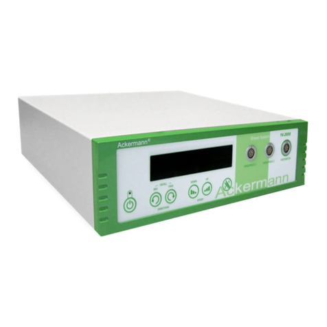
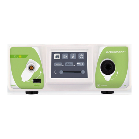
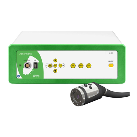
ACKERMANN Fusion 16-2091 User manual

SHAVER SYSTEM
Ackermann
www.ackermannsurgical.com
• Ackermann Fusion™ FullHD 3CMOS NTSC/PAL Camera #16-2091
User Manual
Endoscopic Camera System

ENDOSCOPIC CAMERA SYSTEM
Ackermann
Page: 2 // 22
CONTENTS
1. Preface 3
2. Introduction of the unit 3
3. Safety instructions 3
4. Regulatory advice 4
4.1. Compliance 4
4.2. Electromagnetic interferences and electrostatic discharge 5
4.3. Medical device vigilance 5
4.4. End of lifecyle 5
5. Installing the unit 5
5.1. Connections 5
5.2. Activation 6
5.3. Activation of the device with a Fusion Card 7
6. Operating guidelines 7
6.1. Selecting the surgical speciality 7
6.2.Congurationofthefunctionsofthecameraheadbuttons 7
6.3.Whitebalance 8
6.4. Focusing 9
6.5. Functionatilities 9
6.5.1. Video settings 9
6.5.2. Other parameters 10
6.6. Completion 10
6.7. General settings menu 10
6.8.Informationmenu 10
6.9. Connections menu 11
6.10.Creatingauserprole 11
7. Description of front and back panels 11
7.1. Mains socket 11
7.2. Video outputs 11
7.3. Peripheral outputs 12
7.4.Keysandsymbolsonthefrontandbackpanels 12
8. Suggested decontamination procedures 13
9. After-sales service and maintenance 14
10. Troubleshooting 14
11. Technical characteristics 15
12. Electromagnetic compatibility 16
12.1.Cablelength 17
12.2. Recommended separation distances 17
12.3. Electromagnetic emissions 17
12.4.Magneticandelectromagneticimmunity 18
12.5. Electromagnetic immunity, radiofrequencies 19
13. Symbols 20
14. Appendix 21
15. Contact details 21

Ackermann
Page: 3 // 22
SHAVER SYSTEM
1. PREFACE
We thank you for your purchase of the Ackermann Fusion™ Endoscopic Camera System.
Inordertomakethebestuseofitwhilehavingallthenecessaryprecautionsatyourdisposal,itisessentialforyouto
becomeacquaintedwiththismanual.
Thesentencesdisplayingthesymbol correspond to points requiring special attention.
The sentences displaying the symbolrepresentitemsofinformation.
To facilitate installation and use of the device, we have attempted to make the device manual more practical.
Consequently,referencestotheproductpresentationpageontheinsidecover(likeC1)forexample)willbeprovidedfor
easier viewing of the relevant product parts.
Thisusermanualisanintegralpartofthedevice.Itmustbemadeavailabletotheuser.Properuseandcorrecthandling
ofthedeviceentailfollowingtheseinstructions.Theuseraloneshallberesponsibleforanydamagethatmayresultfrom
improper use.
2. INTRODUCTION OF THE UNIT
This is a 3CMOS FULLHD medical camera.
Itsergonomicallydesignedsensor,automaticshutter,goodsensitivity,excellentresolutionandfaithful
color-renderingmakeitidealasamedicaltoolforrigidorexibleendoscopy.
This camera comes with:
• A control unit
• A camera head with integrated 15-34 mm zoom lens
•Videocables
•Apowercable
•Aperipheralcable
•Twocommunicationcables
• A set of 6 Fusion Cards
• A user manual
• A Quickstart guide
FortheUnitedStatesandCanada,the“hospitalgrade”powercordsuppliedandtheconnectormustbeusedwitha
“hospital grade” mains socket.
Thisequipmenthasbeendeliveredtoyouinpackagingtoberetainedforuseiftransportingthedevice
3. SAFETY INSTRUCTIONS
Read the User Manual.
Thisusermanualisanintegralpartofthedevice.Itmustbemadeavailabletotheuser.Properuseandcorrecthandling
ofthedeviceentailfollowingtheseinstructions.Theuseraloneshallberesponsibleforanydamagethatmayresultfrom
improper use.

ENDOSCOPIC CAMERA SYSTEM
Ackermann
Page: 4 // 22
• Comply with the conditions of use and storage
• Do not expose the device to excessive dust
•Thedeviceshouldbeopenedonlybyacompetenttechnicianauthorizedbythemanufacturer
•Donotinsertmetalobjectsintothedevice.Thisistoavoidanyriskofelectricalshock,re,shortcircuitorhazardous
emissions
• Do not expose the device to splashed water or to damp
•Useonlytheaccessoriessuppliedwiththedeviceorrecommendedasoptionsbythemanufacturer
•Thiscameraisnotaame-proofdevice.Therefore,itmustnotbeusedinthepresenceofammableanaesthetics
•Thisdevicewasnotdesignedtobeusedinanionisingenvironment
• This device is not sterile
• The surface temperature of the camera can reach 41°C (aft er a few minutes’ use). Therefore, avoid any contact with this
area
•Thecameraisintendedforusebyqualied,trainedprofessionals,inanoperatingtheatre
• Prior to plugging in the device, check that the mains voltage and mains frequency indicated on the device correspond to
the power system values
•Priortoactivation,ensurethatneitherthedevicenorthepowercableisdamaged.Deterioratedcablesandconnectors
mustbereplacedimmediately
•Donotdropthedevice.Ifthedevicefalls,donotreconnectthedevicebutsenditbacktoyouruthoriseddistributoror
directly to the Ackermann after-sales service department
•Noadditionalmultiple-socketoutletsorextensioncordsmustbeconnectedtotheEMsystem
Toavoidanyriskofelectricalshock,thisdevicemustbeconnectedonlytoapowersystemequippedwithprotective
grounding
Devicesconnectingtotheinput/outputportsmustcomplywiththeIEC60950-1standard
Any modication of this device without authorisation from the manufacturer is prohibited. If the medical device
ismodied, an inspectionandatest mustbe carried out toensurethatthe medicaldevice complies with thesafety
regulations
Checkwiththemanufacturerregardingthecompatibilityofyourendoscopeandyourlightsource,priortouse
Itisadvisabletohaveasecondsurgicalcameraintheoperatingtheatresothatactioncanbetakenifthedevicefails
to perform or if a deterioration in performance is noticed
Thisdeviceistobeusedonindividuals(patients)ttoundergoanendoscopicprocedure
The potential equalization plug located at the back of the medical device can be used to equalize the grounding
potential of the medical device with that of all the devices plugged into the power main in the environment. Use the shared
groundingsysteminthehospitalorthebuilding
Deviceconnectingtotheinput/outputportsmustcomplywiththeIEC60950-1standard
4. REGULATORY ADVICE
4.1. COMPLIANCE
Thisproductwasdesignedandmanufacturedbyacompanywithacertiedqualitysystem.Itmeetstherequirementsof
European directive 93/42/CEE, on medical devices. Consequently, it particularly meets the standards of electrical safety
(IEC)andelectromagneticcompatibility(CEM)adhoc.

Ackermann
Page: 5 // 22
SHAVER SYSTEM
4.2. ELECTROMAGNETIC INTERFERENCES AND ELECTROSTATIC DISCHARGE
Although this product complies with CEM standards, it may in very special circumstances interfere with other devices, or
itselfbetheobjectofinterferencefromotherdevicesoranunfavourableelectromagneticenvironment.
Imagetransfersfromthecameratoamonitormaybesusceptibletoelectromagneticdisturbancesandelectricsystem
disturbances.
Inordertoavoidthesesituations,itisadvisableto:
• Ensure of the quality of the electric power system (especially the grounding of all devices and medical carts
• Keep the device away from electromagnetic sources (e.g. compressors, motors, transformers, HF generators, etc.)
4.3. MEDICAL DEVICE VIGILANCE
Likeanymedicaldevice,thisdeviceissubjecttothestipulationsgoverningmedicaldevicevigilance,andthereforeany
seriousmalfunctionmustbereportedtothecompetentauthoritiesandtothemanufacturerasquicklyandasaccurately
aspossible.Formanufacturercontactdetails,refertothelastpageofthemanual.
4.4. END OF LIFECYCLE
ThisdevicecarriestherecyclingsymbolincompliancewithEuropeandirective2002/96/CEEonWasteElectricaland
Electronic Equipment (DEEE or WEEE). By correctly disposing of this device you are helping to prevent harmful eff ects on
the environment and on human health.
The symboldisplayedonthedeviceandontheaccompanyingdocumentationindicatesthatthisproductcannotunder
anycircumstancesbetreatedashouseholdwaste.Itmustthereforebedeliveredtoawastecollectioncentreforthe
recycling of electrical and electronic equipment.
Indisposingofit,pleasecomplywiththewasteeliminationnormsineffectinthecountrywhereitisinstalled.
For further details on the treatment, recovery and recycling of this device, kindly contact your nearest retailer who will
advise you on the procedure to follow.
5. INSTALLING THE UNIT
This medical device is intended for use by a qualied surgeon during endoscopic exploration. No special training is
required to install it. Kindly refer to the instructions in this manual.
Placethecontrolunitonitsbaseandhavetohandthevariousaccessoriesrequiredtooperateit.
5.1. CONNECTIONS
• Connect the power cord to the mains socket of the camera C2 and a video lead to one of the video output ports: We
recommendselectingtheDVIoutputC6forconnectingthemainsurgicalmonitor
• Connect the second end of the video lead to the video input port on the monitor
•IfyouwishtocontrolcertainfunctionalitiesoftheAckermanninsuatorortheAckermannlightsource,connectthese
totheAckermannCOMsocketonthecamera’scontrolunitC9intendedforthispurpose,usingthetwocablesprovided
Connecting the endoscope to the sensor:
• Turn the ring on the endoscope-holder on the camera head clockwise
• Once the endoscope is inserted, release the ring
•Ifthesensorhastobelockedintopositionontheendoscope,theringshouldbeturnedintheoppositedirection
•ConnectthepotentialequalizationcabletotheequipotentialplugC13atthebackofthedevice

ENDOSCOPIC CAMERA SYSTEM
Ackermann
Page: 6 // 22
5.2. ACTIVATION
Tooptimize thequalityof theimages obtained with this product,alwaysbe suretoconnect the camera head before
turning on the control unit
•ConnectthepowercabletotheplugC2atthebackofthecamera
•ConnecttheDVI-DcabletothecorrespondingoutputportC6atthebackoftheproductandtothecorrespondinginput
port on the monitor
> TheHDSDIoutputproducesaprogressive1080signal
•Ifneeded,connectothermonitorsorperipherals,preferablyusingtheHDSDIoutputportsC8
> HDSDIoutputportsproduceaninterleaved1080signal
> HDSDIoutputportsarepreferredwhenaverylongcableisnecessary
• Turn the activation switch S2 to position “1”
> Thecameratakesabout30secondstocomeon.TheAckermannlogoisdisplayedonthe
screen during this interval
> TheashingLEDstandbybutton,andtheappearanceof“standby”onthescreenindicatethatthe
camera is properly activated
• Connect the camera head to the control unit via the dedicated connector C1
•Touchthescreen,ORpresstheStandbybuttontoaccessthemainmenu
•SelectasurgicalspecialityfromLaparoscopy,Cystoscopy,Hysteroscopy,ENT,ArthroscopyandFlexibleEndoscopy,by
clickingtheassociatedsymbol
> Once the selection is made, the camera is in surgery mode
•Afterconnectingthelightcableandtheendoscope,lmawhitesurfaceandlaunchtheWhiteBalancebypressingthe
dedicatedbuttononthetouchscreeninterface,orthecamerahead’spre-programmedbutton
> When the surgical monitor appears indicating “AWB OK” and the chronometer starts, this signals that the white
balancehassuccessfullybeenset
> Thechronometershowstheoperatingtimebydefault(thestartingpointbeingwhenthewhitebalanceisset).
However,thischronometercanbesetbeforehandifnecessary,independentlyofthewhitebalance
•Thevideosettingshavebeendenedforeachsurgicalspeciality.However,theycanbemodied,ifnecessary,during
surgery
> 3ofthese(Brightness,SharpnessandRedGain)canbedirectlyaccessedfromthemainscreen.Alltheothers
(Gamma,BlueGain,Color,RedPhase,Gain,NoiseReduction,andAperture)canbeaccessedbyclickingthe
“MoreSettings”button.Thisisadrop-downlist.Toscrollthroughtheparameters,touchtheleftsection(the
parameterheadings)withyournger
• Press “Close settings” to exit and return to the main screen
•Youcanatanytimeduringsurgerytoreturntothefactorysettingsforthesurgicalspecialitybyclickingthe“Specialities
presets”button.
•Pressthe“STOP”buttonattheendofthesurgery
You can at this stage:
Returntothemainmenubyclickingthe“Completed”button
OR
Createauserprolefromthesettingsusedduringtheoperation
OR
Loginifyouwishtoaddthissetofsettingstoyourprole

Ackermann
Page: 7 // 22
SHAVER SYSTEM
Beforeconnectinganendoscope(orbroscopes)tothecameralens,checktheconditionofthisendoscope(clean
distal lens, setup if necessary)
5.3. ACTIVATION OF THE UNIT WITH A FUSION CARD
Scan a Fusion Card on the read area provided on the lexan housing (next to the Ackermann logo)
• Scanning a standard Fusion Card:
> Activate the camera directly on the surgical screen, in the surgical application corresponding to the Fusion Card
scanned
• Scanning a personal Fusion Card:
> Activate the camera directly on the surgical screen, in the surgical preset corresponding to the Fusion Card
scanned.IftheuserproleassociatedwiththeFusionCardscannedshowsmorethanonepreset,then
anintermediatestageforselectingthedesiredpresetwillbenecessary
• Scanning an administrator Fusion Card:
> Activate the camera in the administrator menu
6. OPERATING GUIDELINES
6.1. SELECTING THE SURGICAL SPECIALITY
Thiscameracanbeusedinvariousmini-invasivesurgicaloperations.
Select the speciality from the pre-entered list. This loads the video parameters for the application accordingly:
• LAPAROSCOPY
• HYSTEROSCOPY
• CYSTOSCOPY
• ENT
• ARTHROSCOPY
•FLEXIBLEENDOSCOPY
Note 1: EachofthesespecialitiescanbeaccessedbyscanningtheFusionCardonitsdedicatedareaZ1onthe
controlunit.Thiscandedoneatanytime.IftheFusionCardisscannedwhileasurgicaloperationisinprogress,then
conrmationwillberequested
Note 2:Ifyouhaveenteredcustomizedparametersintoauserprolebeforehand,thenyoucanselectthisuserprole
eitherbyusingthe“Login”button,orbyscanningyourpersonalFusionCardonthededicatedareaZ1ofthecontrolunit
ifthecontrolunitislinkedtoyourpersonalprole
6.2. CONFIGURATION OF THE FUNCTIONS OF THE CAMERA HEAD BUTTONS
Thisoperationisperformedonthecorrespondingpageofthemenuinterface,whichcanbeaccessedfromthe
dedicated“Camerahead”button:
Clickthebuttonyouwishtocongure(B1,B2orB3).
Selectthetypeofpress(shortpressorlongpress)andthecorrespondingfunctiondesired,andconrm.
Repeatthisprocedureforeachofthethreebuttons.
Thecongurationselectedforeachofthethreebuttonswillbeenteredintotheuser’spersonalprole.

ENDOSCOPIC CAMERA SYSTEM
Ackermann
Page:8//22
Belowisthecomprehensivelistofthecongurablefunctions:
Short press Long press
No action No action
Brightness + Brightness +
Brightness - Brightness -
Lightsource-Intensity+ Lightsource-Intensity+
Peripheral 1 Peripheral 1
Peripheral 2 Peripheral 2
Mirror Mirror
Freeze frame Freeze frame
Recording images on the camera (if equipped with an integrated
recorder) AWB
Record / Stop video recording on the camera (if equipped with an
integrated recorder) Insuators(RUN/HighFlowRate/STOP)
Lightsource (ON/OFF)
(a) Recording images on the PC Recording images on the camera (if equipped with an integrated
recorder)
(b)Record/StopvideorecordingonthePC Record / Stop video recording on the camera (if equipped with an
integrated recorder)
(a) Recording images on the PC
(b)Record/StopvideorecordingonthePC
Bydefault,thefollowingcongurationisapplied(factorysetting):
B1 (short press / long press): Brightness - / Light source
B2(shortpress/longpress):Brightness-/Insuator
B3 (short press / long press): No action / AWB
Mirror mode: An “M” is displayed on the monitor to indicate that the mirror mode (inverted image) is active, and disappears
when it is deactivated.
Freeze mode: an «F» is displayed on the monitor to indicate that the freeze mode is active, and disappears with it is
deactivated.
6.3. WHITE BALANCE
Thewhitebalancecanbesetin2ways:
•Fromthetouchscreeninterface,clickthewhitebalancebutton
•Fromoneofthecameraheadbuttons,dependingonyourprogramming(onlypossiblewithlongpress)
You should proceed as follow:
•Oncethecameraispairedwiththeendoscope,theambientlightreducedtoaminimumandthelightsourceactive,lm
a white surface

Ackermann
Page: 9 // 22
SHAVER SYSTEM
•Setthewhitebalance;theBALANCINGINPROGRESSmessageisdisplayedonthescreen
•ContinuetolmthewhitesurfaceuntiltheBALANCEOKmessageisdisplayedonthescreen
Note 1: Settingthewhitebalancecausesthechronometertobeactivated,signallingthestartofthesurgeryandtherefore
theavailabilityofadditionalfunctionalities,particularlythoselinkedtotheimagequalitysettings
Note 2: IftheAckermannlightsourceisconnectedtotheAckermanncamerabythecommunicationcablesupplied,then
settingthewhitebalancewillcausetheLEDtolightupifitwaspreviouslyoff
Intheeventthatthewhitebalanceissetduringanoperation,i.e.insidethepatient,theendoscopemustbepulledout
ofthetrocarandthewhitebalancemustbesetagainusinggauze
6.4. FOCUSING
Oncetheendoscopeisconnectedandthelightsourceisactivated,slowlyturnthelensfocusringtondapositionwhere
theobjectsbeingobservedaresharp.
Focusingonafairlydistantpointhelpsobtainadequateelddepthfortheoperationandthereforeavoidshavingtodo
retouching too regularly
6.5. FUNCTIONALITIES
6.5.1. VIDEO SETTINGS
Oncethewhitebalanceisset,orthe“Start”buttonhasbeenpressed,accesstothevideosettingsisauthorised.
Inthisway,itispossibletoworkdirectlyonbrightness,sharpnessandredgain.
Additionalsettingsareavailablebyclickingthe“Moresettings”button.
Thefollowingparameterscanbemodied:
Brightness Thisparametervariesthegeneralbrightnessoftheimage
Blue gain Colorimetryshiftfromwhitetoblue
Red gain Colorimetry shift from white to red
Color Modiescolorsaturation
Noise reduction Reduces the noise in an image
Window Shutter window analysis: surface of the image on which the camera analyses the quantity of light
received,inordertoadjustthespeedoftheshuttertoobtainarightexposuretime.Usetheauto-
matic mode or change it according to the scope size
Gamma Modiesthedynamicsofthedarkareas:
+1reducesthedifferencebetweenthelightportionsandthedarkportions,thereforemakingthese
dark areas appear less so.
-1 does the opposite: the dark portions are made even darker.
Sharpness Modiesthesharpnessoftheimagetoobtaina3Deffectorontheotherhand,softenstheimagewith
theanti-moirélterforexibleendoscopes.
Gain Modiesthebrightnesslevelincasesofmediocrelightingconditions
0483

ENDOSCOPIC CAMERA SYSTEM
Ackermann
Page: 10 // 22
Red phase Colorimetry phase shift from Orange to Magenta
Clickthe“Closesettings”buttononcetoreturntothepreviousmenu.
6.5.2. OTHER PARAMETERS
HD Recording:
IfyourcameraisequippedwithanintegratedHDrecorder,youcansetHDimage/videorecordingfromtheinterfacemenu
usingthecorrespondingbuttonsorfromthebuttonsonthecameraheadifthesehavebeenprogrammedaccordingly.
Insuators:
If your camera is connected to theFusion insuator viathe communication cableprovided, youcan select fromthe
parametersmenuwhetherornottodisplayinformationabouttheoperatingstatusoftheinsuatorsonthesurgical
monitor’s OSD.
Inparticular:
Feedbackoninstantaneouspressureinthepneumoperitoneum;
Feedbackonwarningmessagesfromtheinsuators.
Inaddition,oneofthebuttonsonthecameraheadcanbecongured(longpressonly)tocontroltheFusioninsuators
accordingtothefollowingsequence:Startinsuationinlowow/Changetohighow/Stopinsuation.
6.6. COMPLETION
Oncetheoperationiscompleted,pressthe“STOP”button.Youwillbegiventheoption:
•Tocreateauserprole
• To log in, if you have not already done so
•Tosaveanymodicationstothesettingsinyourpersonalprole,ifyouhavenotalreadydoneso
• To exit
Note:Ifyouarealreadyloggedin,youcanopttosavethemodicationstoyourpersonalprole.
Inparticularyouwillbeabletosave:
•Modicationstothevideosettings
•ModicationstotheAckermannlightsourceintensitysetting(lastsettingused)
•ModicationstotheAckermanninsuatorpressuresetpoint(lastsettingused,with15mmHglimitation,andmode)
•Modicationstothesettingsonthesurgicalmonitorsupportedmodelsonly)
Oncetheselectionhasbeenmade,youcanoverwritetheexistingpreset,orcreateanotherone
6.7. GENERAL SETTINGS MENU
The general settings menu is used to:
• Set the light intensity on the touch screen
• Select the display messages and the display of the instantaneous pressure in the pneumoperitoneum from the Fusion
insuator
• Select the language
• Pause the live video when a photo is taken to verify its quality
6.8. INFORMATION MENU
The information menu is used to access a rapid start-up product guide.

Ackermann
Page: 11 // 22
SHAVER SYSTEM
6.9. CONNECTIONS MENU
Theconnectionsmenuisusedtoobtaintheconnectionstatusofallofthesystem’sdevices.
Inparticular,thecamerahead,theAckermannlightsource,theAckermanninsuators,theAckermannPCPanelandthe
Surgical Monitor.
Note: The icon for this menu changes to orange when at least one of the products on the system is disconnected.
6.10. CREATING USER PROFILES
•Clickthe“Loginorcreateaprole”button
•Clickthe“Createaprole”button
> ActivatingthecamerawithablankFusionCardgivesdirectaccesstothefollowingstage
•Clickthetexteldandenterthedesiredprolename
•Clickthe“Return”button
•Selectasurgicalspeciality.Thiswillformthebasisforthevideoparameters
•Clickthe“Createaprole”buttonORscanablankFusionCardontheareaprovidedforthispurposeonthelexanhousing
(next to the Ackermann logo)
•Amessageisdisplayedforafewsecondsindicatingthatthedevicesupportsthecreationofaprole
• You can then:
> Renametheproleand/orthepresetbyclickingthe“Manage”button
> Deleteone(ofthe)prolepreset(s)byclicking“Manage”
> Usethepresetcreatedbyclickingonit
> Logoutbyclickingthe“Logout”button
Notes:IfablankFusionCardhasbeenscannedatleastonce(duringactivationand/orwhilesavingacreatedprole),then
theprole(andthepresets)createdwillbeautomaticallylinkedtothisFusionCcard.Apadlockiconwillbedisplayedon
thisprole.Thismeansthat:
> ThepresetslockedinthisprolecannotbemodiedwithoutthecorrespondingFusionCard
> ThenamesofthepresetsandtheprolenamecannotbemodiedwithoutthecorrespondingFusionCard
7. DESCRIPTION OF FRONT & BACK PANELS
7.1. MAINS SOCKET
ThecamerareceiveselectricalpowerbymeansofthemainspluglocatedonthebackpanelC2,whichmustbeconnected
tothemainspowersupplybytheleadsuppliedwiththecamera.Thisplugcarriesafusetrapaswellasamasterswitchfor
turning on the device.
The camera uses T2.5AL - 250V fuses.
Whenreplacingafuse,thecameramustbeunpluggedandthesametypeoffusemustbeused.
The T in “T2.5A” means “time-delay”. Only use fuses marked UL/CSA.
7.2. VIDEO OUTPUTS
Thefollowingvideooutputportsareavailableonthiscamera:DVIC6,HD-SDIC8,RGBSC5,Y/CC10andcompositeC11.
The DVI output port provides the best image quality in 1080p format over short distances.
HD-SDI output ports are used to transport the video signal over long distances (screen at a distance of up to 50 m).

ENDOSCOPIC CAMERA SYSTEM
Ackermann
Page: 12 // 22
7.3. PERIPHERAL OUTPUTS
Two(2)peripheraloutputportsareavailableC12andtheseareusedwitha3.5mmjackleadformanagingtwoperipherals
(forexample:aprinterandavideorecorder)fromthebuttonsonthecamerahead.
Thedevicesconnectingtothe“VIDEOOUT”and“PERIPHERAL”portsmustbecompliantwithstandardIEC60950.
7.4. KEYS & SYMBOLS ON THE FRONT & BACK PANELS
ThekeysandsymbolsonthebackpanelareforidentifyingthecamerainaccordancewithinternationalstandardsIEC
60601-1,IEC60601-2-18,IEC60417andEN980(SeeAppendix1)
Thetablebelowdescribesthebackandfrontcomponents:
C1 Connector for the camera head
C2 Main power socket
C3 RS232 output
C4 Service line
C5 RGBS video output
C6 DVI-Dvideooutput
C7 Ethernet output
C8 SDIoutput
C9 ConnectionstoAckermannproduct(lightsourceandinsuator)
C10 Y / C video output
C11 Composite video output
C12 Peripheral connections
C13 Equipotential plug
C14 USB storage device port
L1 Touchscreen
S1 Standbybutton
S2 Powerbutton
Z1 Read area of Fusion Card

Ackermann
Page: 13 // 22
SHAVER SYSTEM
8. SUGGESTED DECONTAMINATION PROCEDURES
Disinfecting the camera control unit
Thecameracontrolunitisanon-heat-resistantmedicaldeviceanddoesnotwithstandimmersion;consequently,it
shouldbedisinfectedusinganon-wovenmediumsaturatedwithadisinfectantdetergent
This device is not drip-proof. Do not splash liquid on this product
Asdecontaminationislinkedtotheproducts,methodsand/ortoolsused,decontaminationisthesoleresponsibility
of the staff concerned
Thedevicemustalwaysbedisconnectedbeforeanycleaningprocedureiscarriedout
Thisdeviceisnotautoclavable
Existing alkaline solutions for the disinfection of certain medical devices are NOT RECOMMENDED for disinfecting
this device
Disinfecting the camera head
Pre-disinfection cleaning Disinfection Sterilization
Immersioninanenzymatic
cleaning solution (Aniosyme
DD1, Hexanios G + R or surface
cleaning ((Anios wipes)).
Immersioninaglutaraldehydesolution(Anios
Laboratory-Steranios2%)
Low-temperature sterilisation
with hydrogen peroxide or oxide
Anyotherdisinfectionmethodsareprohibited,andthemanufactureracceptsnoliabilityforanydamagecausedby
using such methods
Itisadvisabletouseadisposable,sterile,protectivecoveronthecameraregardlessofthesterilisationprocedure
followed and throughout the surgical operation
Thecameraisnotautoclavable
Thecameraisnotcompatiblewithautomaticwasher-disinfectors
Existing alkaline solutions for the pre-disinfection of certain medical devices are NOT RECOMMENDED for pre-
disinfecting our cameras
Itisessentialforthepartscomingintocontactwiththedisinfectanttobethoroughlyrinsed
Use soft non-woven cloths for wiping the lenses dry so as not to scratch them
Theproceduresdescribedinthissectionaregivenasguidance,andcannotunderanycircumstancesbesubstituted
forocialrecommendationsordirectives
Theconnectoronthecameraequippedwithitssealingcapcanbeimmersed.Tracesofwaterarevisiblejustasthe
connectorsealisremoved(runoffandcondensation).Itisthereforeessentialtodrytheinsideofthecapwellbefore
reusing it

ENDOSCOPIC CAMERA SYSTEM
Ackermann
Page: 14 // 22
Disinfecting the lens surfaces
Adirtylenssurfacecaninterferewithobservation.Thelenssurfacemustnothaveanymarksorsmudges.
Toavoidscratchingthelenssurface,neveruseabrasiveclothsorspongestocleanit
To remove dust, dirt and other impurities not originating from the patient, wipe clean with a soft , lint-free cloth
moistenedwithethanolor70%iAckermannpylalcohol.Whencleaning,wearglovesforprotectionfromchemical
products.
Ensurethattheequipmentiscompletelydrybeforeuse.
Use soft non-woven cloths to clean the lenses so as to avoid scratching them.
Please read the cleaning, disinfection and sterilization instructions given in the “General Reprocessing Instructions”
procedure
9. AFTER-SALES SERVICE & MAINTENANCE
This device does not require any special maintenance operations.
Note:Misuseofthedeviceisnotcoveredbythewarranty.
Ifafaultpersistsandthedevicehastobereturnedtotheafter-salesservicedepartment,ensurethatitisshippedinits
original packaging.
Similarly,itisadvisabletoreturnthedeviceinitsentirety(controlunit,powercables).
Kindlyattachtotheshippingorderashortexplanatorynoteaboutthefaultnoted.Theequipmentmustbedisinfected
beforeitisreturnedforrepair.Whenreturningtheequipment,checkitsconditionandnoteanyexceptionsontheshipping
orderifnecessary,andconrmthesewiththeshipperbyregisteredmailwithin48hours.Ifanyequipmentshippedbyus
suffersdamageduringtransport,thetotalamountforrepairswillbechargedeithertotheshipperifnoticationofthe
exceptionshasbeengivenwithinthedeadline,orfailingsuch,totherecipient.Intheeventofanincident,kindlycontact
our customer service department or your nearest sales representative.
10. TROUBLESHOOTING
The indicator light on the standby switch S1 does not light up on start-up:
•Checkthatthemainssocketatthebackofthecameraisproperlyconnectedtothepowersupplyandthatthegeneral
switchatthebackofthecameraisintheoperatingposition(“I”)
•Checkthatthefusesareingoodcondition(onlyusethefusesspeciedonthebackpanel).
The indicator light on the standby button S1 comes on but no image appears on the screen:
•Checkthatthesensorisproperlyconnectedtothecontrolunit(ifnot,acolorbarwillbedisplayed),andthatitislming
aworkableimage
•Checkthatthecontrolunitonthecameraiscorrectlyconnectedtothemonitor(cableingoodcondition,plugscorrectly
pushed in)
•Ifthevideochannelhasseveralcomponents,connectthecameradirectlytothemonitortoverifythattheproblemisnot
with one of the peripherals
• Check that the monitor is in fact switched on, wired to the correct video input and that the image settings are at the mid-
point position (color, light and contrast)
•Checkthelightsource,thelightcableandtheendoscope
The image is blurred and white all over:
• Check that there is no condensation on the lens
•Checkthatthesensorisnotaimedatanobjectthatistoobright

Ackermann
Page: 15 // 22
SHAVER SYSTEM
• Check the lens setup
Ifthereisnoimageoriftheimageisnotdisplayed,unplugandre-plugyourdeviceorresetthecameratothefactory
settings
The image is extremely light or dark:
•CheckthattheBRIGHTNESSparameterisnotatthemaximumorminimumsetting
• Check that the APERTURE used is not too wide or too narrow
• Check that the camera head is correctly connected to the control unit
• Check that the light intensity from the light source is not too low or too high
•Turnoffandturnbackonthecontrolunit
Ifthefaultpersistsanditbecomesnecessarytoreturnthecameratotheafter-salesservicedepartment,besuretoship
itinitsoriginalpackagingafterdisinfectingit.Similarly,itisadvisabletoreturnthecamerainitsentirety(controlunit,
sensor,lens,cables).Kindlyattachtotheshippingorderanexplanationconcerningthefaultnoted.
Theequipmentmustbedisinfectedbeforeitisreturnedforrepair.
When returning the equipment, check its condition and note any exceptions on the shipping order if necessary, and
conrmthesewiththeshipperbyregisteredmailwithin48hours.Ifanyequipmentshippedbyussuffersdamageduring
transport,thetotalamountforrepairswillbechargedtotheshipperifnoticationoftheexceptionshasbeengivenwithin
the deadline, or otherwise to the recipient.
11. TECHNICAL SPECIFICATIONS
Control unit
Main functions:
• Class 1 device, CF-type applied part
•3programmablebuttons
• Application and user MENUS
• Automatic compensation function for defective pixels
- RF transmitter:
•Type:RFID
• Frequency : 13,56 MHz
• Modulation feature : OOK
•Transmitterpower:70mW(+18dBm)
Video output:
• CVBS: 1.0 V [P-P] / 75 ohms Negative Sync,
•Y/C:Y:1.0V[P-P]/75ohms,C:0.286V[P-P](NTSC),C:300Vp-pV[P-P](PAL)/75ohmsNegativeSync,
• RGB: 3x0.7 V [P-P] & 0.3V [P-P] / 75 ohms
•HD-SDI:0.8V[P-P]/75ohmsSMPTE292M
•DVI-D3x0.7Vcc/&0,.3Vcc/75Ω)
Environment:
• Operating temperature: +10°C / +40°C
•Operatinghumidity:30%to75%
• Transport and storage temperature: -10°C / +45°C
•Transportandstoragehumidity:20to85%
• Operating, storage and transport atmospheric pressure: 700hPa to 1 060hPa
•Controlunitisnotdrip-proof(IPXO)
•Notsuitableforuseinpresenceofammablegaz.Recommendationofuseinanoperatingroominaccordancewith
applicableregulations
• Compliant with European directive 93/42/CEE.

ENDOSCOPIC CAMERA SYSTEM
Ackermann
Page: 16 // 22
•CompliantwithinternationalstandardsIEC60601-1;IEC601-2-18;IEC60417andEN980
•Dimensions(WxHxD):310x136x385mm
• Control unit weight: 4300g
• Electric power supply: 100 - 230 VAC @ 50 Hz-60 Hz
•Electricityconsumption:38-50VA
• Two T2.5AL - 250V fuses (Marked UL/CSA only)
• Continuous operation
Camera head
• CF-type applied part
• Sensor: 3 CMOS
• Acquisition in native 16:9 format
• Progressive scan technology
•Resolution:HDTV1080pformat:1920x1080pixels
•Denition:1080lines
• Sensitivity: 5 lux
• Signal/Noise ratio: 54dB
•Cablelength:3m
• Sensor dimensions (D x H): 149 x 53 mm
• Sensor weight: 270g
12. ELECTROMAGNETIC COMPATIBILITY
Alltheinformationbelowisbasedontherequirementsofstandardstowhichthemanufacturersofelectricalmedical
devicesmustadhere(asstatedinstandardIEC60601-1Ed4).
Themedicaldevicecomplieswiththeelectromagneticcompatibilitystandardsinforce.However,theusermustmake
sure that any electromagnetic interference does not create an additional risk, such as radiofrequency transmitters, or
other electronic devices.
This chapter contains the information required for you to install and use your medical device in optimum conditions in
termsofelectromagneticcompatibility.Thedifferentmedicaldevicecordsmustbekeptawayfromeachother.
Some types of mobiletelecommunicationdevicessuchas mobile phones mayinterferewith themedicaldevice.The
separationdistancesrecommendedinthischapterMUSTbecompliedwith.Themedicaldevicemustnotbeusednear
anotherdeviceorplacedontopofit.Ifthiscannotbeavoided,correctoperationofthedeviceinoperatingconditions
mustbecheckedpriortouse.
TheuseofaccessoriesotherthanthosespeciedorsoldbyAckermannasreplacementpartsmayincreasetheemission
or reduce the immunity of the medical device.

Ackermann
Page: 17 // 22
SHAVER SYSTEM
12.1. CABLE LENGTH
Cables and accessories Maximum length Test type In compliance with
Videocables
Mainscable
Mainsboundarycable
Communicationcable
< 3 meters
RFemissionCISPR11,ClassB CISPR11,ClassB
Harmonic current emission IEC61000-3-2
Voltagechangesandicker IEC61000-3-3
Electrostatic discharge immunity IEC61000-4-2
Transient electromagnetic immunity IEC61000-4-3
Electricalfasttransient/burstimmunity IEC61000-4-4
Surge immunity IEC61000-4-5
Immunitytoconducteddisturbances,
inducedbyradio-frequencyelds IEC61000-4-6
Radiatedimmunity–magneticelds IEC61000-4-8
Voltage dips, short interruptions and
voltage variation immunity IEC61000-4-11
12.2. RECOMMENDED SEPARATION DISTANCES
ThemedicaldeviceisdesignedtobeusedinanelectromagneticenvironmentinwhichinterferencescausedbyRF
radiation are controlled.
Theuserorinstallerofthemedicaldevicemayhelptopreventelectromagneticinterferencebymaintainingaminimum
distance, depending on the maximum power of the radiofrequency transmission equipment.
RFmobilecommunicationdevices(includingperipheralssuchasantennacablesandexternalantennas)should
notbeusednearerthan30cm(12inches)fromanypartofthemedicaldevice,includingthecablesspeciedbythe
manufacturer.Ifthisisnotrespected,theperformanceofthesedevicesmaybeimpaired.
12.3. ELECTROMAGNETIC EMISSIONS
Themedicaldeviceisdesignedforuseintheelectromagneticenvironmentdescribedinthetablebelow.Theuserand/
orinstallermustensurethatthemedicaldeviceisusedintheenvironmentdescribedbelow.
Emission test Conformity Electromagnetic environment – comments
Electromagnetic radiation dis-
turbance(radiatedemissions)
(CISPR11)
Group 1 The medical device uses RF energy for its internal operation.

ENDOSCOPIC CAMERA SYSTEM
Ackermann
Page:18//22
Disrupting voltage on the power
terminals (Conducted emis-
sions)(CISPR11)
Class B
TheEMISSIONScharacteristicsofthisdeviceallowittobeusedinindustrial
areasandinhospitalenvironments(classAdenedinCISPR11).Whenitis
usedinaresidentialenvironment(forwhichclassBdenedinCISPR11is
normally required), this device may not off er adequate protection for radio
frequency communication services.
The user may need to take corrective actions, such as relocating or redirect-
ing the device.
A professional healthcare environment.
Harmonic current emission
(IEC61000-3-2)
Conforming
Voltage variations, voltage
uctuationsandicker
(IEC61000-3-3)
Conforming
12.4. MAGNETIC & ELECTROMAGNETIC IMMUNITY
Themedicaldeviceisdesignedforuseinthemagneticandelectromagneticenvironmentdescribedinthetablebelow.
The user and/or installer must ensure conformity of the electromagnetic environment.
Immunity test Test level according to
IEC 60601
Conformity level Electromagnetic
environment / comments
Electrostatic discharge (ESD)
(IEC61000-4-2)
±8kVcontact
± 15 kV in the air
±8kVcontact
± 15 kV in the air
A professional healthcare
environment
Electricalfasttransientbursts
(IEC61000-4-4)
± 2 kV for electricity supply
lines
± 2 kV for electricity
supply lines
± 1 kV for signal ports
A professional healthcare
environment
A professional healthcare
environment
Shockwaves(IEC61000-4-5) ± 1 kV in diff erential mode
± 2 kV in common mode
± 1 kV in diff erential mode
± 2 kV in common mode
A professional healthcare
environment
Magneticeldatassigned
industrial frequency
(IEC61000-4-8)
30 A/m 30 A/m A professional healthcare
environment
Voltage dips, short interruptions
and voltage variations
(IEC61000-4-11)
0%UTfor0.5cycles
A0°,45°,90°,135°,180°,225°,
270°and315°0%UTfor1cycle
70%UTfor25cyclesat50Hz
For 30 cycles at 60 Hz
Single-phase: at 0
0%UTfor0.5cycles
A0°,45°,90°,135°,180°,225°,
270°and315°0%UTfor1cycle
70%UTfor25cyclesat50Hz
For 30 cycles at 60 Hz
Single-phase: at 0
A professional healthcare
environment
Iftheuseofthesystemrequires
continuous operation during
mains power outages, it is
advisabletosupplythemedical
device using a separate current
source (UPS, etc.).

Ackermann
Page: 19 // 22
SHAVER SYSTEM
12.5. ELECTROMAGNETIC IMMUNITY, RADIOFREQUENCIES
Themedicaldeviceisdesignedforuseinthemagneticandelectromagneticenvironmentdescribedinthetablebelow.
The user and/or installer must ensure conformity of the electromagnetic environment.
Immunity test Test level Conformity level Electromagnetic
environment / comments
CAUTION:RFmobilecommunicationdevices(includingperipheralssuchasantennacablesandexternalantennas)shouldnotbeused
nearerthan30cm(12inches)fromanypartofthemedicaldevice,includingthecablesspeciedbythemanufacturer.Ifthisisnot
respected,theperformanceofthesedevicesmaybeimpaired.
Radiated radiofrequency
electromagneticeld
(IEC61000-4-3)
10 V/m
80MHzat2.7GHz
80%MAat1kHz
10 V/m
80MHzat2.7GHz
80%MAat1kHz
A professional healthcare
environment
Neareldsemittedbywireless
RF communication devices
(IEC61000-4-3provisional
method)
9 V/m
710 MHz, 745 MHz,
780MHZ,5240MHz,
5550MHz,5785MHz
27 V/m
385MHz
28V/m
450MHz,810MHz,
870MHz,930MHz,
1720MHz,1845MHz,
1970 MHz, 2450 MHz
9 V/m
710 MHz, 745 MHz,
780MHZ,5240MHz,
5550MHz,5785MHz
27 V/m
385MHz
28V/m
450MHz,810MHz,
870MHz,930MHz,
1720MHz,1845MHz,
1970 MHz, 2450 MHz
A professional healthcare
environment
Conducteddisturbances,
inducedbyRFelds
(IEC610004-6)
3 V
150KHzat80MHz
6VinISMfrequencybandand
bandbetween0.15MHZand80
MHZ,
80%MAat1KHz
3 V
150KHzat80MHz
6VinISMfrequencybandand
bandbetween0.15MHZand80
MHZ,
80%MAat1KHz
A professional healthcare
environment

ENDOSCOPIC CAMERA SYSTEM
Ackermann
Page: 20 // 22
13. SYMBOLS
Symbol Description
S
L
C
I
Button
Screen
Socket
Label(rearpaneloftheunit)
Formedicaldevices,thissymbolisassociatedwiththeyearofmanufacture.Thelatterisdenoted
byfourgures
Formedicaldevices,thissymbolisassociatedwiththenameandaddressofthemanufacturer
Protective grounding
Class 1 product
Compliant with European directive 93/42/CEE
An equipotential grounding socket conductor other than protective grounding or a neutral conductor,
fordirectconnectionbetweentheelectricalequipmentandthepotentialequalisationbusbar.Kindly
refertostandardIEC60601-1,3rdedition
T UL/CSA time-delay fuses
Video output ports and peripheral control output port
Data input and peripheral output
CF-type device
Electronicandelectricalequipmentmarketedafter13/08/2005.Thissymbolindicatesthatthis
productisnottobetreatedwithhouseholdwaste.
Read the user manual
RF transmitter
Upper and lower temperature limit of the medical device
Humidityrangewithinwhichthemedicaldevicecanbesafelyexposed
Atmosphericpressurelimit.Indicatestherangeofatmosphericpressurewithinwhichthemedical
devicecanbesafelyexposed
Cataloguenumber
Serialnumber
Table of contents
Other ACKERMANN Medical Equipment manuals
Popular Medical Equipment manuals by other brands

Dynatronics
Dynatronics Hausmann 6175 Installation & operation instructions

Pensar Medical
Pensar Medical WoundPro Quick reference card

ADL
ADL soft air simplex wds user manual

Medstrom
Medstrom MMO 3500 user manual

Interacoustics
Interacoustics Orion installation instructions

EYEBEAM
EYEBEAM SOAP S quick start guide

ATS Dental
ATS Dental B-ONE Operation and maintenance instruction manual

Enabling Technologies
Enabling Technologies Dynamique Biski owner's manual

Teleflex
Teleflex LMA Supreme Instructions for use

UroSystem
UroSystem UroDapter user manual

MERCIAN
MERCIAN Micro Torque MT5000 Operating instructions manual

RMS
RMS FREEDOM60 manual