Acmeda BOX 120 User manual

EXTERNALWIREGUIDE
INSTALLATIONMANUAL
September2013

CONTENTS
September2013
ThismanualistobereadinconjunctionwiththeProductSpecifications&Assemblymanual
SECTIONNO.DESCRIPTIONPAGENO.
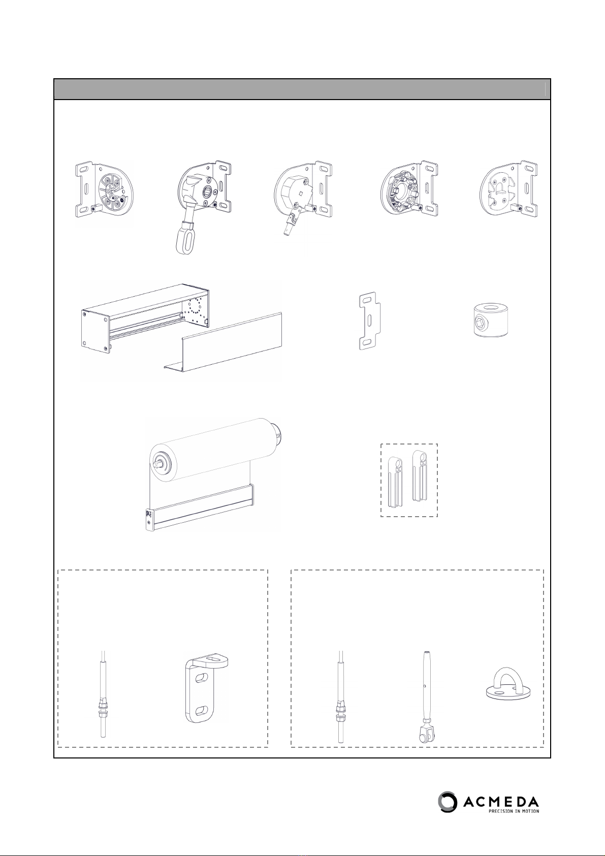
SECTION1−ITEMSREQUIRED1.1
SECTION2−INSTALLATION2.1
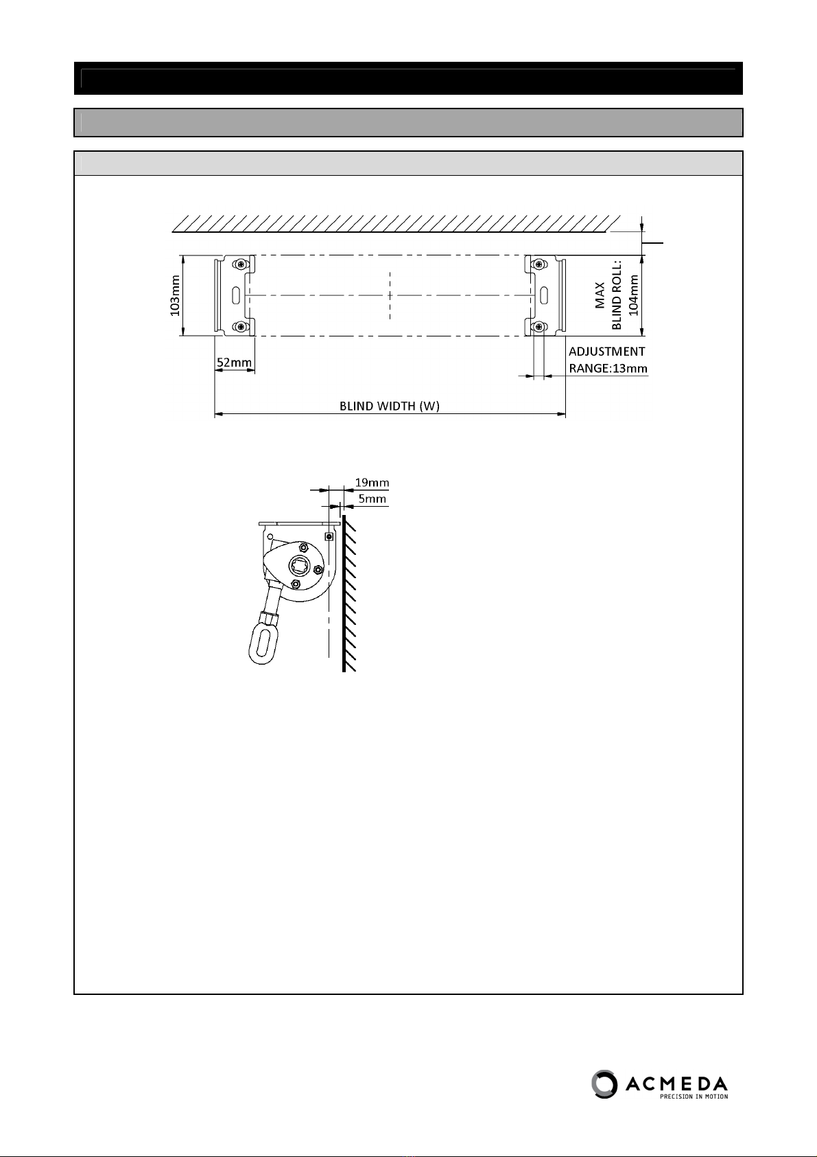
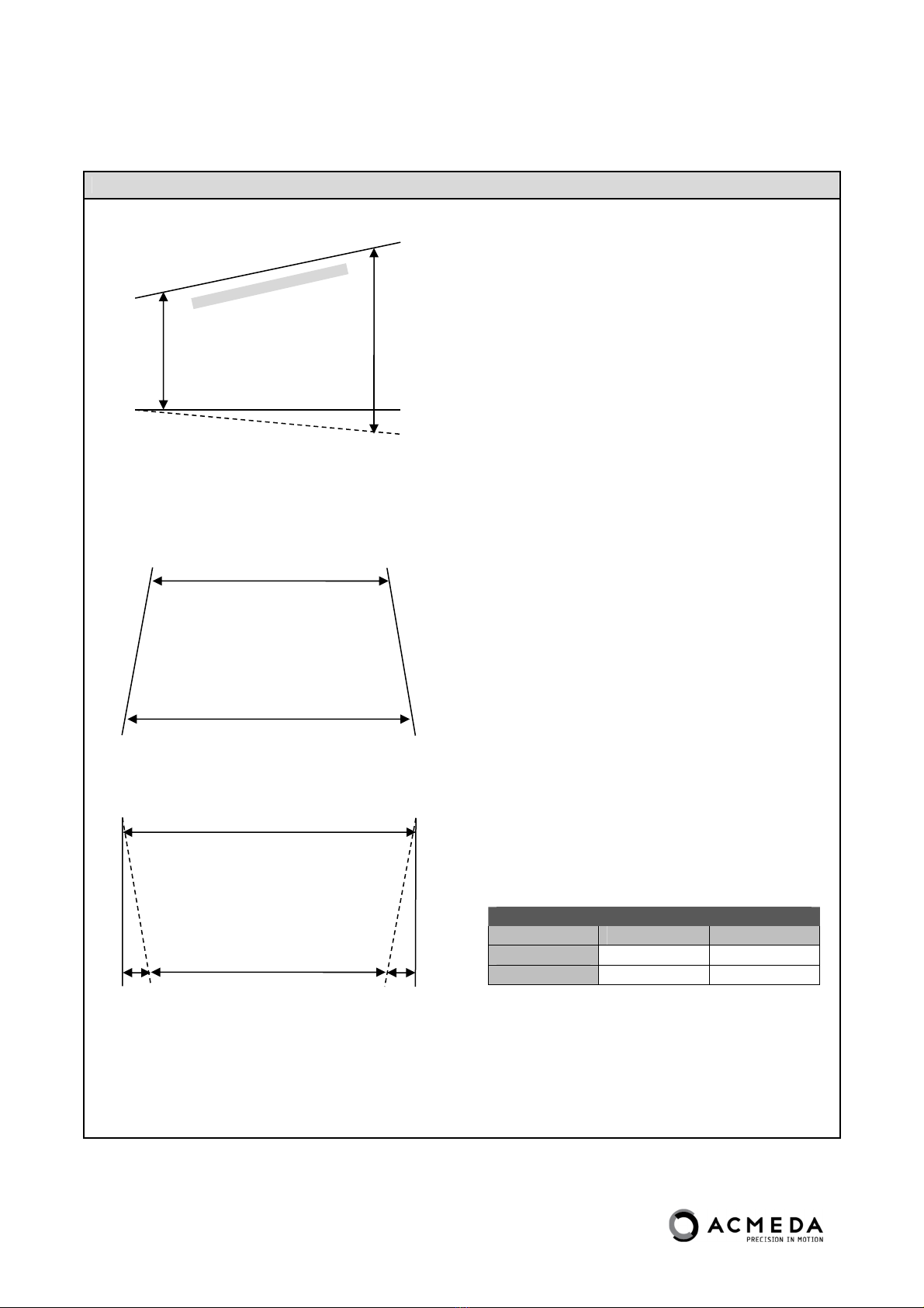
PARTA–PREPARINGINSTALLATIONSPACE2.1
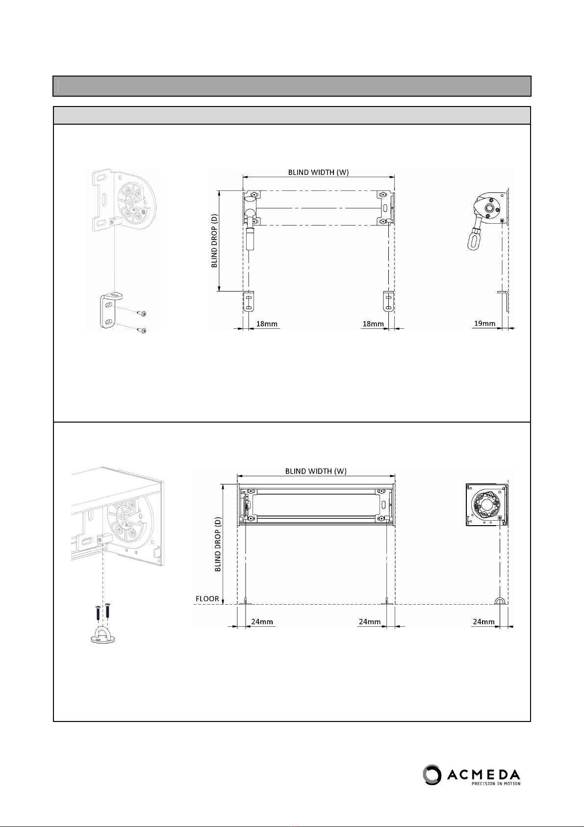
PARTB–BRACKET/BOXINSTALLATION2.3
PARTC–WIREGUIDEINSTALLATION2.4
PARTD–BLINDINSTALLATION2.8
PARTE–BOXCOVERINSTALLATION(FORBOX120SYSTEMONLY)2.10
PARTF–TENSIONGUIDELINES2.12
SECTION3−TROUBLESHOOTING3.1
DISCLAIMER
INTRODUCTION
ThisInstallationmanualhasbeenproducedbyAcmedatosupplythenecessaryinformationforsafeandcorrectinstallationofthissystem.
INSTALLERSRESPONSIBILITY
Beforeinstalling,pleaseread&ensureyouunderstandthesafetyinformationandinstallationinstructionsasdefinedinthisinstallationmanual.
Ifyoudonotfullyunderstandtheseinstructions,contactAcmedaforclarificationbeforeinstalling.
TheInstallerisresponsibletoensurethatallinstallationpersonnelhavebeenadequatelytrainedonthesafe&correctinstallationandoperation.
TheInstallerisresponsibletoensurethataJobSafetyAnalysisorSafeWorkMethodStatementiscompletedpriortoinstallationtoidentifyhazards,todetermine
appropriateriskcontrolmeasuresandtoimplementthecontrolmeasures.
TheInstallerisresponsibletoensurethatsupportingstructuresaresoundandcanadequatelysupporttheload.
TheInstallerisresponsibletoensurethatthedevisesusedtoanchortheproducttothesupportingstructurearesuitablefortheapplication.
SAFETYINFORMATION
EnsureJobSafetyAnalysis/SafeWorkMethodStatementiscompletedandactionstoreducerisksareimplemented.
EnsurethatelectricalworksaredoneonlybyaLICENSEDELECTRICIAN.
DONOTmodifyanyofthecomponentsofthissystem.
PERSONNELREQUIREMENTS
Onlysuitablytrained/qualifiedpersonnelshouldundertakeinstallation.
DISCLAIMER
Acmedahasusedreasonablecareinpreparingtheinformationincludedinthisdocument,butmakesnorepresentationsorwarrantiesastothecompletenessoraccuracy
oftheinformation.Informationissuppliedupontheconditionthatthepersonsreceivingtheinformationwillmaketheirowndeterminationastoitssuitabilityfortheir
purposespriortouse.Acmedaassumesnoliabilitywhatsoeverforanydamagesincurredbyyouresultingfromerrorsinoromissionsfromtheinformationincluded
herein.Acmedareservestherighttomakechangeswithoutfurthernoticetoanyproductstoimprovereliability,functionordesign.
COPYRIGHT
COPYRIGHT©ACMEDA2013
Allrightsreserved.Nopartofthisdocumentmaybereproducedorutilisedinanymeans,byanymeans,electronicormechanicalincludingphotocopying,recordings,or
byanyinformationstorageorretrievalsystem,withouttheexpresspermissionfromAcmeda.

Page1.1EXTERNALWIREGUIDEInstallationManual|September2013
©Copyright2013|AllRightsReservedAcmeda(InternationalGroup)
SECTION1−ITEMSREQUIRED
TOOLSREQUIRED
Saw
Saw
Drill
ScrewDriver–PhilipsHead&FlatHead
JawPliers
AllenKeySet
Mallet
Scissors
Punchtool/template
MeasuringTape
Pencil
ADDITIONALITEMSREQUIRED(NOTSUPPLIED)
ToassembleanEXTERNALWIREGUIDE,thefollowingnon‐stockeditemsarerequired:
Fixingsformountingbrackets/hardware(Ensureappropriatefixingsareusedtosuitapplication)

Page1.2EXTERNALWIREGUIDEInstallationManual|September2013
©Copyright2013|AllRightsReservedAcmeda(InternationalGroup)
BLINDITEMSREQUIRED
Checkthatyouhaveallrequiredblinditems:
1. Brackets
2. BoxSquare120+RequiredInstallationItems
3. CompleteBlind
4. WireGuideComponents
1.
Brackets
2.
BoxSquare120+RequiredInstallationItems
BracketSpacers(x2)
AdjustableStop(x2)
3.
CompleteBlind
4.
WireGuideComponents
FACEFIXINSTALLATIONFLOORFIXINSTALLATION
SWAGEADJUSTABLE
TERMINAL+4.2m
WIRE
(X2)
WALLMOUNTINGBRACKET
(X2)
OR
SWAGEADJUSTABLE
TERMINAL+4.2m
WIRE
(X2)
TURNBUCKLESET
(X2)
ROUNDEYE
PLATE
(X2)
OR
+
+ +
+
OR OR
+ ++

Page2.1EXTERNALWIREGUIDEInstallationManual|September2013
©Copyright2013|AllRightsReservedAcmeda(InternationalGroup)
SECTION2−INSTALLATION
PARTA–PREPARINGINSTALLATIONSPACE
STEP1–CHECKINSTALLATIONSPACEFORCLEARANCE&STRUCTURALSUPPORT
ChecktheInstallationSpaceandensureadequateclearanceisprovidedforthesystem
NOTE:ForTopFixInstallationsallow5mmfromthewall
totheedgeofthebrackettoprovideclearancefor
weightbarendcaps.
Ensurebracketscanbeinstalledintoastructurallysupportingsubstrate(Thismaymeantheinstallerneedsto
preparespacepriortocommencementofinstallation)
Minimum
clearance
aboveblind
roll:6mm

Page2.2EXTERNALWIREGUIDEInstallationManual|September2013
©Copyright2013|AllRightsReservedAcmeda(InternationalGroup)
STEP2–CHECKVERTICAL&HORIZONTALINSTALLATIONDIMENSIONS
VERTICALDIMENSIONS
HORIZONTALDIMENSIONS
IfW2≥W1,W1=BlindWidth
(proceedtoSectionC)
IfW2<W1,seetableforlimits
Maximumwidthdifference
Box120Open
X16mm10mm
Y16mm10mm
IfXandYarewithinlimits(asindicatedintheabove
table)theninstallationcanbecompletedusingW1as
BlindWidth.
Ifnotconsiderfurtheractionsforsquaringthe
installationspace(e.g.packingoralternativebracket
selection)
H1H2
Checkiftopofinstallationspaceislevel.
IfH1≠H2,correctiveactionsmayneedtobe
consideredpriortoinstallation
W2
W1
W1
W2
XY

Page2.3EXTERNALWIREGUIDEInstallationManual|September2013
©Copyright2013|AllRightsReservedAcmeda(InternationalGroup)
PARTB–BRACKET/BOXINSTALLATION
STEP1–FIXBRACKETSTOWALL/CEILINGUSINGAPPROPRIATEFIXINGSTOSUITAPPLICATION
OPENBLINDSYSTEM
FACEFIX
TOPFIX
NOTE:Ensurebracketsareinstalledalignedandlevel.Refertodeductionsforbracketpositioning.
BOX120SYSTEM
Box120SystemcanbefixedtothewallinthecentrepriortofixingthebracketstoensureBoxislevel.
FACEFIX
TOPFIX
NOTE:EnsureBracketSpacersareusedwithBox120System

Page2.4EXTERNALWIREGUIDEInstallationManual|September2013
©Copyright2013|AllRightsReservedAcmeda(InternationalGroup)
PARTC–WIREGUIDEINSTALLATION
STEP1–MARK&SECUREBOTTOMWIREGUIDEFIXINGTOWALLORFLOOR
OPENBLINDSYSTEM
NOTE:DimensionsrefercentreofwireandapplytobothFaceFixingandFloorFixinginstallations.
BOX120SYSTEM
NOTE:DimensionsrefercentreofwireandapplytobothFaceFixingandFloorFixinginstallations.
X2Brackets
X2Plates

Page2.5EXTERNALWIREGUIDEInstallationManual|September2013
©Copyright2013|AllRightsReservedAcmeda(InternationalGroup)
STEP2–ATTACHTERMINALTOWALLMOUNTINGBRACKET
FACEFIX‐WALLMOUNTINGBRACKET
NOTE:EnsurebothTerminalsareattachedtobrackets.
FLOORFIX‐ROUNDEYEPLATE
i) Remove1Nut&2
WashersFromStud
Terminal
ii) ThreadTurnbuckle
SetontoTerminal
iii) RemovePin&Clip
iv) PositionJawover
RoundEyePlate
v) Replace&Secure
Pin&Clip
NOTE:EnsurebothTerminalsareattachedtoRoundEyePlates.
Allow
approximately
20mmfor
tensioning
Allow5‐10mm
beforetensioning
20mm
20mm

Page2.6EXTERNALWIREGUIDEInstallationManual|September2013
©Copyright2013|AllRightsReservedAcmeda(InternationalGroup)
STEP3–INSERTWIREGUIDEFLOATONTOWIRE
FeedFloatingEndCapontoWire(atbothends)
NOTE:Repeatonoppositeside.
AllowEndCaptoSlidealongwire
STEP4–ADDADJUSTABLESTOP(FORBOX120SYSTEMONLY)
NOTES:
EnsureAdjustableStopisinsertedaftertheWireGuideFloat.
Donottightenatthisstep
Repeatonoppositeside

Page2.7EXTERNALWIREGUIDEInstallationManual|September2013
©Copyright2013|AllRightsReservedAcmeda(InternationalGroup)
STEP5–SECUREWIRETOTOPTERMINAL
InsertWirethroughterminal
Measure&cutwireapproximately
5‐10mmaboveterminal
Tightengrubscrewsecurelytoretain
wire(ensurethreadofgrubscrewdoes
notstrip)
STEP6–ADJUST&SECUREADJUSTABLESTOPTOWIREGUIDES(FORBOX120SYSTEMONLY)
NOTE:Ensurethataminimumclearanceof5mmisleftbetweenthebottomoftheAdjustableStopandbottomoftheBoxto
preventtheweightbarfromtwisting.
5mm(min)

Page2.8EXTERNALWIREGUIDEInstallationManual|September2013
©Copyright2013|AllRightsReservedAcmeda(InternationalGroup)
PARTD–BLINDINSTALLATION
STEP1–INSERTCONTROLENDFIRSTTHENSWINGIDLERENDINTOADAPTOR
GEARCONTROL
EnsureIdlerPinLocksintoAdaptor
STARHEADMOTOR(FORSTARHEADMOTORONLY)
Removeretainingscrewfromthelockringbeforeinsertingblindasshownabove.
NOTE:Ensurescrewissafelystoredasitwillneedtobere‐inserted.

Page2.9EXTERNALWIREGUIDEInstallationManual|September2013
©Copyright2013|AllRightsReservedAcmeda(InternationalGroup)
STEP2–REPLACE&SECURERETAININGSCREWINTOLOCKINGRING(STARHEADMOTORONLY)
ScrewuntiltightinordertolocktheMotorinposition
STEP3–INSERTFLOATINGENDCAPSINTOENDCAPHOUSING
Beforeapplyingtensiontowireguides,insertendcapfloat
intoweightbarendcaps.
Ifmoreclearance/spaceisrequired,lifttheweightbaratone
endtoinsertthesecondfloat.
NOTE:
Ifballastisrequired,insertpriortofittingendcap.Forexternalapplicationsensureballastiscorrosionresistantandiscompatible
withaluminium.

Page2.10EXTERNALWIREGUIDEInstallationManual|September2013
©Copyright2013|AllRightsReservedAcmeda(InternationalGroup)
PARTE–BOXCOVERINSTALLATION(FORBOX120SYSTEMONLY)
STEP1–SWINGBOXCOVERINTOPLACE
EnsureCoverclipstotab
IFthelipofthecoverisnotlocationuseapairofplierstoadjustthelockingfeatureupordownasrequired

Page2.11EXTERNALWIREGUIDEInstallationManual|September2013
©Copyright2013|AllRightsReservedAcmeda(InternationalGroup)
STEP2–FIXCOVERWITHSCREWORRIVET(OPTIONAL)

Page2.12EXTERNALWIREGUIDEInstallationManual|September2013
©Copyright2013|AllRightsReservedAcmeda(InternationalGroup)
PARTF–TENSIONGUIDELINES
Tocompletetheinstallationensureadequatetensionisappliedtothewireguides.40kgoftensionisrecommendedforthe
system.Ifasuitabletensionmeterisnotused,thechart/imagesbelowprovideaguideonhowtoapplyanominaltensionof40kg
TensionGuidelineTable
DropNo.ofRotations
(FaceFix)
No.ofRotations
(FloorFix)
1.0m10.5
2.0m21
3.0m21
4.0m31.5
FACEFIX
1.PullSwageTerminaldowntoremove
slackandhandtightenbottomnutuntil
contactwithbracket
2.ApplytensionbyholdingSwage
Terminalstillandrotatingbottomnutas
required(No.OfRotationsindicated
above)
3.Tightenandlocktopnutwhile
supportingSwageTerminaltoensure
tensionismaintained
(repeatonotherterminal)
NOTE:Repeatonoppositeside.
FLOORFIX
1.PullSwageTerminaldownandhand
tightenTurnbuckletoremoveslack
2.ApplytensionbyholdingSwage
TerminalandrotatingTurnbuckleas
required(No.OfRotationsindicated
above)
3.WhileholdingtheTurnbuckleSecure
bothtopandbottomnutstoensurethe
systemislocked(ensuretoonlylockone
atatime)
NOTE:Repeatonoppositeside.
FIX FIX
FIX
FIXFIX

Page3.1EXTERNALWIREGUIDEInstallationManual|September2013
©Copyright2013|AllRightsReservedAcmeda(InternationalGroup)
SECTION3−TROUBLESHOOTING
NO.PROBLEMCAUSESOLUTION
1Ripplesalongsidesoffabric
Blindrolledupforanextendedperiod
oftime.
Thisoccurrenceisinherenttorollersystemsandismore
prevalentinsomefabrics.Leaveblinddownfor1–4hours;
mostripplesshoulddisappear.
Notenoughweightinweightbar.RefertoProductSpecs.
Addballast.
Installationisnotsquare. Checkblindrollisinstalledlevel.
Fabricpermanentlydamageddueto
inadequatehandlingduringassembly,
transportation,installationoruse.
Replacefabricandensureitishandledwithcare.
2
Blinddoesnotfullyopen/jams
Positionofwireguidesatbaseis
incorrect.
Checkifwireguidefixingatfloor/basearepositionedinline
withtheTopTerminal.Iffixingistoofarinwardsofthe
terminalthenreposition.RefertoPartC,Step1ofthis
documentforwireguidepositioningdetails.
Incorrectmotorstoplimitsused. Refertomotorinstructionstoresetstoplimits.
3Unevenweightbar
Blindrollisnotlevel,thusweightbar
appearsuneven.Ensureblindisinstalledlevel.
Blindhasbeenoperatedinexcessive
windconditions.
Checkblindrollwhentheblindisfullyraised.Ifripplesare
evidentonroll,openblindfully(withoutthepresenceof
wind)toallowtheblindtotrackdownevenly.Raiseand
lowerblindanumberoftimestocheckoperation.
Fabricisnotinstalledstraight.Ensurefabricisassembledstraightontotubeandweight
bar.
Table of contents
Other Acmeda Window Blind manuals
Popular Window Blind manuals by other brands

HunterDouglas
HunterDouglas Standard Cordlock, Moveable Slat Specialty... Operating Systems

Roto
Roto ZJA M installation manual

Benthin
Benthin M4000 instructions

SelectBlinds
SelectBlinds Cordless Honeycomb Shades installation instructions

Rollos
Rollos Medium Plus Basis Assembly and operating instructions

3 Day Blinds
3 Day Blinds 2 Getting started