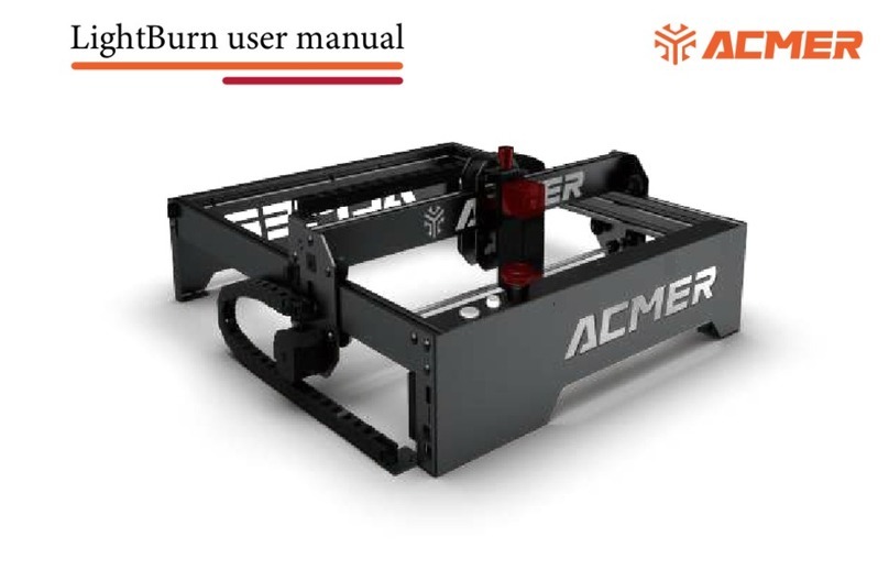
ACMER P2 User manual

https://www.facebook.com/groups/1614455505653986

USER MANUAL V1.0
Acmer 3D Electronlc Technology Co., Ltd.
ACMER P2
LASER ENGRAVER

1.Contents
2.Disclaimer and Safety Guidelines
3.Machine Parameters
4.Machine Description
5.Machine List
6.Installation Steps
7.Port and Key Function Introduction
8.Software Tutorials
9.APP Tutorials
10.Air Assist
11.FAQ
12.After Sale
01
02
03
04
05
06
12
13
22
27
30
33
1.CONTENTS
Thank you!
Dear friends, thank you for purchasing ACMER P2 Laser Engraver. We appre-
ciate your approval of our products and services, and we sincerely hope that
you will enjoy this product and that it will bring you joy.
If you have any problem in using it, please feel free to let us know and we will
do our best to help you. You can join our Facebook group to share your ideas
and can get ideas and inspirations from others. Thank you again for your
support and we will continue to provide quality products and services!
Facebook Group: https://www.facebook.com/groups/1614455505653986
Facebook : https://www.facebook.com/profile.php?id=100088576630671
01 02
03 04
05 06
07 08
09 10
11 12
13 14
15 16
17 18
19 20
21 22
23 24
25 26
27 28
29 30
31 32
33 34

Laser engraving machine will produce laser light, it is strictly prohibited to
point the laser at any living body.
During the engraving and cutting process, please ensure that the machine
is within the visual range of the operator.
When using the laser engraving machine, the operator and the personnel in
its vicinity must wear laser safety glasses, please do not operate the laser
without wearing protective glasses (laser goggles)!
When the machine is running, please do not touch the laser beam to avoid
personal injury.
Minors (especially children over 14 years old) must use the machine under
the supervision of an adult throughout!
engraving machine work will produce a lot of smoke, please place the ma-
chine in a ventilated environment before work, and ensure that there is no
other flammable materials near the engraving machine, it is recommended
to place a metal mat under the machine.
2.Disclaimer and Safety Guidelines
This machine is not recommended for commercial use.
01 02
03 04
05 06
07 08
09 10
11 12
13 14
15 16
17 18
19 20
21 22
23 24
25 26
27 28
29 30
31 32
33 34

Machine Size
Engraving Size
Machine Weight
Focal Length
Laser Power
Laser Wavelength
Laser Type
Power Input
Communication Method
Compatible Software
Compatible Systems
Engraving Material
Engraving File Format
Engraving Accuracy
Fuselage Material
600*650*170mm
420*400mm
6.5kg
5mm
10W/20W/30W
450±5nm
Diode Laser
DC 24V
USB / APP
LaserGRBL / Lightburn
MAC, Windows
NC, DXF, BMP, JPG, PNG, etc
0.01mm
Aluminum profiles
3.Machine Parameters
wood, bamboo, paper, plastic, leather, PCB board, aluminium
oxide, non-reflective coating and lacquered metal, ceramic
5mm 5mm
10W 20W/30W
Focal Length
01 02
03 04
05 06
07 08
09 10
11 12
13 14
15 16
17 18
19 20
21 22
23 24
25 26
27 28
29 30
31 32
33 34

Front Component
Air Pipe
Rear Component
X-axis Assembly
1.
3.
5.
7.
Air Pump
Left Component
Right Component
Laser Module
2.
4.
6.
8.
4.Machine Description
4
5
7
8
6
1
3
2
01 02
03 04
05 06
07 08
09 10
11 12
13 14
15 16
17 18
19 20
21 22
23 24
25 26
27 28
29 30
31 32
33 34

Laser Module x1
USB Cable x1
Belts x2
Power Adapter x1
Pipe Connector x1
Card Reader+TF Card x1
Machine Key x1
Air Pipe x1 Test Plank x2
Screwdriver x4M3*6 Screw x12 M4*8 Screw x4
Front component x 1
Left component x 1
Rear component x 1
Right component x 1
Frame
5.Machine List
Accessories
X-axis assembly x 1
Brushes x1
Circuit Group x1
Laser Goggle x1
Wrench x1
Air Pump x 1
01 02
03 04
05 06
07 08
09 10
11 12
13 14
15 16
17 18
19 20
21 22
23 24
25 26
27 28
29 30
31 32
33 34

Front Component x 1
Left Component x 1
6.1 You will need to prepare the following sections.
6.1.1 Install the box in the direction shown and place it on a horizontal table.
6.Installation Steps
Right component x 1
M3*6 Screw x 12
Rear Component x 1
01 02
03 04
05 06
07 08
09 10
11 12
13 14
15 16
17 18
19 20
21 22
23 24
25 26
27 28
29 30
31 32
33 34

6.1.2 Use M3*6 socket head cap screws to fix the profile from the top.
(Note: There is no need to lock the screws in this step, lock the screws again in step
6.3.3.)
(Note: There is no need to lock the screws in this step, lock the screws again in step
6.3.3.)
6.1.3 Insert the right assembly to the rear assembly in the same way and
then also secure it with 3 M3X6 screws.
01 02
03 04
05 06
07 08
09 10
11 12
13 14
15 16
17 18
19 20
21 22
23 24
25 26
27 28
29 30
31 32
33 34

6.2 You will need to prepare the following sections.
X-axis assembly x 1 M4*8 Screwx4
6.2.1 Secure the X-axis assembly to the gantry frame using four M4*8 screws
from each side.
01 02
03 04
05 06
07 08
09 10
11 12
13 14
15 16
17 18
19 20
21 22
23 24
25 26
27 28
29 30
31 32
33 34

6.3 You will need to prepare the following sections.
Note: The left and right belt tightness needs to be consistent.
6.3.2 Use an Allen wrench to adjust the belt tightness.
Install the left and right belts.6.3.1
Belt x2 Laser Module x 1
1 2
34
01 02
03 04
05 06
07 08
09 10
11 12
13 14
15 16
17 18
19 20
21 22
23 24
25 26
27 28
29 30
31 32
33 34

6.3.4 Remove the laser module, slide it into the slide slot, and tighten the side
screws to secure it.
6.3.3 Slowly move the X-axis assembly back and forth to ensure smooth
movement in the Y-axis direction and then lock the previously unlocked
screws.
01 02
03 04
05 06
07 08
09 10
11 12
13 14
15 16
17 18
19 20
21 22
23 24
25 26
27 28
29 30
31 32
33 34

6.4 Connecting wires
1
2
3
4 1
01 02
03 04
05 06
07 08
09 10
11 12
13 14
15 16
17 18
19 20
21 22
23 24
25 26
27 28
29 30
31 32
33 34

7.Port and Key Function Introduction
2
34
8
6
5
9
1. Power socket: input DC 24V power supply
4. TF card holder: insert TF card, used for APP operation to store data
5. Power switch
6. Key switch: lock and unlock by key rotation
9. Rotary module port: connect with rotary module
8. Rotary module changeover switch: please toggle the switch to the right end
when using the rotary module
2. USB port: communicate with computer through USB data
3. Emergency stop switch: press the emergency stop button, the machine stops
working; rotate the emergency stop button clockwise, the machine resets
1
10
11
7
7. Buzzer: will sound and flash when open flame is detected.
11. Flame sensor switch: turn on or off the flame detection function.
10. Air pump interface: air pump can be connected and controlled by software.
01 02
03 04
05 06
07 08
09 10
11 12
13 14
15 16
17 18
19 20
21 22
23 24
25 26
27 28
29 30
31 32
33 34

8.Software Tutorials
8.1 LaserGRBL Tutorial
8.1.1 Select "115200", and then click "Connect".
ACMER laser engraver supports the most popular engraving software LaserGRBL and
Lightburn.
LaserGRBL is an open source, easy to use and powerful software that is perfect for
novice users to use, but LaserGRBL only supports Windows systems (Win XP/Win 7/
Win 8/XP/ Win 10). For Mac users, you can choose to operate LightBurn, which is also
an excellent engraving software, but it costs $40 (with a free one-month trial for the
first installation), and this software also supports Windows systems.
If you want to download and install LaserGRBL, you can get the data directly from the
TF card, or you can visit the official website of Laser GRBL to download; for Lightburn
users, you can Lightburn official website to download.
8.1.2 Click the Unlock button.
Note: If you are using this software for the first time, please get the driver file from
the TF card "Software->Drivers" file and install it.
01 02
03 04
05 06
07 08
09 10
11 12
13 14
15 16
17 18
19 20
21 22
23 24
25 26
27 28
29 30
31 32
33 34

8.1.3 Start engraving
① Click the "Open File" button.
② Select the engraving file.
③ Click "OPEN".
④ Brightness, contrast, black and white limit adjustment.
⑤ Select the engraving mode.
⑥ Adjust the engraving quality (recommended quality setting is about 10).
⑦ Click "NEXT".
①
④
⑤
⑥
⑦
②
③
01 02
03 04
05 06
07 08
09 10
11 12
13 14
15 16
17 18
19 20
21 22
23 24
25 26
27 28
29 30
31 32
33 34

⑧ Select the engraving speed (suggest to refer to the engraving parameter table).
⑨ Select "Laser Mode", "M4" for engraving and "M3" for cutting.
⑩ Set the engraving power, 1000 is the maximum power.
Set the engraving size.
Click "Create".
Preview engraving range.
Click "Run Program" to start engraving.
⑧
⑨
⑩
01 02
03 04
05 06
07 08
09 10
11 12
13 14
15 16
17 18
19 20
21 22
23 24
25 26
27 28
29 30
31 32
33 34

8.2.1 Connecting the machine
① Click "Devices", and then click "Create Manually".
② Select "GRBL" and click "NEXT".
③ Select "Serial/USB", and then click "NEXT".
8.2 Lightburn Tutorial
01 02
03 04
05 06
07 08
09 10
11 12
13 14
15 16
17 18
19 20
21 22
23 24
25 26
27 28
29 30
31 32
33 34

⑥ Click "Finish".
④ Set the engraving range of the machine, and then click "NEXT".
⑤ Select the origin of the machine, uncheck the box to return to zero automatically,
and then click "NEXT".
01 02
03 04
05 06
07 08
09 10
11 12
13 14
15 16
17 18
19 20
21 22
23 24
25 26
27 28
29 30
31 32
33 34

⑦ Select "GRBL" and click "OK" after the meal.
⑧ Return to the main interface and select the correct port to complete the connection.
① Click "Setting" and set the speed unit to "mm/min".
8.2.2 Software setup
01 02
03 04
05 06
07 08
09 10
11 12
13 14
15 16
17 18
19 20
21 22
23 24
25 26
27 28
29 30
31 32
33 34
Other manuals for P2
1
Table of contents
Other ACMER Engraver manuals