Vision VE-810 User manual

VE-810 Engraver
Operations Manual
Vision Engraving & Routing Systems
17621 N. Black Canyon Hwy.
Phoenix, AZ 85023
Technical Support 602-439-0700
Fax 602-439-0500
www.visionengravers.com

Copyright ©2009 Vision Engraving & Routing Systems
(A Division of Western Engravers Supply, Inc.)
All Rights Reserved
This publication is protected by copyright, and all rights are reserved. No part of this manual may be
reproduced or transmitted by any means or in any form, without prior written consent from Vision.
Limits of Liability/Disclaimer of Warranty for this Equipment Manual
The information contained within this manual has been carefully checked and is believed to be accurate,
however, Vision makes no representations or warranties for this manual, and assumes no responsibility for
inaccuracies, errors, or omissions that may be contained within this manual. In no event shall Vision be
liable for any loss of profit including (but not limited to) direct, indirect, special, incidental, consequential, or
other damages resulting from any defect or omission in this manual, even if previously advised of the
possibility of such damages.
In the interest of continued product development, Vision reserves the right to make improvements to this
manual and the products it describes at any time, without notice or obligation.

Table of Contents iii
Table of Contents
CHAPTER 1 - BEFORE YOU BEGIN..................................................................................5
INTRODUCTION....................................................................................................................5
SAFETY ..............................................................................................................................5
UNPACKING AND TAKING INVENTORY.....................................................................................6
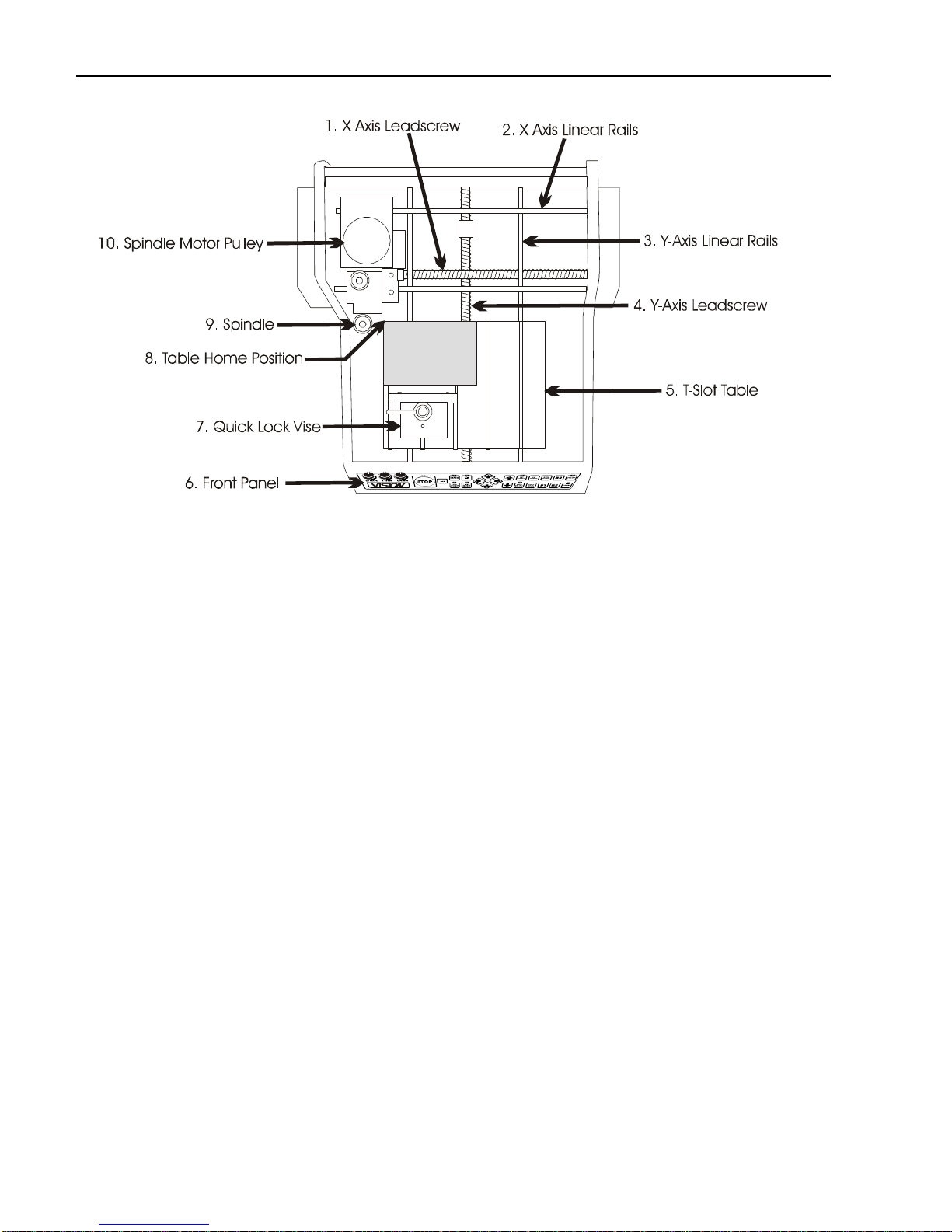
MACHINE DESCRIPTION &TERMINOLOGY ..............................................................................7
CHAPTER 2 - INSTALLATION .........................................................................................13
SOFTWARE INSTALLATION ..................................................................................................13
CONNECTING THE TABLE....................................................................................................19
CONFIGURING THE COMPUTER ...........................................................................................28
CHAPTER 3 - OPERATIONS............................................................................................29
THE FRONT PANEL ............................................................................................................29
HOLDING DOWN MATERIAL..................................................................................................34
DIAMOND DRAG ENGRAVING ..............................................................................................37
ROTARY ENGRAVING .........................................................................................................39
BURNISH ENGRAVING.........................................................................................................41
CHAPTER 4 - OPTIONAL ACCESSORIES......................................................................45
CLAMPING DEVICES...........................................................................................................45
VACUUM CHIP REMOVAL SYSTEM .......................................................................................49
CHAPTER 5 - MAINTENANCE.........................................................................................51
REMOVING CHIPS ..............................................................................................................51
LUBRICATION.....................................................................................................................52
CHANGING THE MOTOR BELT..............................................................................................54
CHANGING THE MOTOR BRUSHES.......................................................................................56
CLEANING THE FAN FILTER.................................................................................................59
REPLACING THE EXTERNAL FUSE........................................................................................60
CHAPTER 6 - TROUBLESHOOTING ...............................................................................63
ENGRAVING PROBLEMS......................................................................................................63
MECHANICAL PROBLEMS....................................................................................................66
INDEX................................................................................................................................59

iv VE810 Engraver Manual

Chapter 1 - Before You Begin 5
Chapter 1 - Before You Begin
Introduction
About This Manual
This manual is designed to provide you with information about your Vision VE-810—
VE-810XD engraver, beginning with unpacking the machine and continuing through
installation and lifetime machine maintenance. This manual does not attempt to teach
you how to engrave, how to use a computer or how to use your engraving software.
Some previous knowledge of engraving terms and the engraving process is assumed.
For information on the Vision Engraving Software, see the Vision Engraving
Software manual. For more information on your individual computer system, see your
computer’s user manual or contact your computer distributor.
Safety
Safety Precautions for the VE-810 Engraver
¾Keep hands clear of the bottom of the spindle during operation.
¾Always stop the machine before making any adjustments.
¾Do not operate the machine with the covers removed.
¾Wear safety glasses when cutting any materials that emit chips.
¾Use extreme caution when inserting or removing cutters.
¾Before any servicing, disconnect the power cord.
¾To avoid electric shock or equipment damage, ensure that the control unit is
connected to the appropriate electrical source as noted in the installation procedures.
¾Never operate the equipment with damaged or frayed power cords, loose connections,
or exposed extension cords where someone can step on the cord and create a tripping
hazard.
¾Be sure to hold the plug, not the cord, when disconnecting the controller from an
electrical socket or power source.

6 VE810 Engraver Manual
¾Place the machine in a location with low humidity and a minimum of dust. Avoid
placing the equipment in direct sunlight or in locations with excessive heat. Follow the
maintenance instructions for proper cleaning of the controller air filter.
¾If your machine does not operate properly; in particular, if there are any unusual
sounds or smells coming from it, immediately unplug it and contact a service
technician or your local distributor.
¾Unplug the machine when it is going to be left unused for an extended period of time.
Unpacking and Taking Inventory
The VE-810 engraving system has been shipped in one carton, unless other accessories
have been ordered with the machine that will not fit in the box. Examine the condition of
the box for external damage. In the event of apparent external damage, notify your
shipping carrier upon receipt, and call your sales representative or Vision immediately.
Note: The shipping container is considered reusable and should be stored for use in the
event of service need or upgrade.
Step1:
Open the foam packed shipping carton. In the top of the carton will be a cardboard box
with all of the machine accessories (including this manual). Open the accessory box and
the following items should be included:
91 VE-810 or VE-810XD Machine
91 VE-810 Warranty Card
91 Vision All Products CD
91 VE810 Table Manual
91 Vision Software Manual
91 Vision Font Catalog
92 Spare 1.5 Amp Fuses (.6 Amp fuses when machine is 220 volt)
91 Power Cord
91 Serial Interface Cable
91 USB Cable
91 Interface Cable Adapter (25 pin to 9 pin)
91 Extra 13 3/4“ Motor Belt
91 Allen Wrench Set
91 Cutter Wrench
91 Quick Lock Vice (mounted on the T-Slot table)
Check to see that all of the items are included. Should any of the contents be missing,
damaged, or of the incorrect type, please call your sales representative or Vision
immediately.
Step 2:
Prepare a clean, level surface to put the engraving machine on. Carefully lift the machine
out of the carton and place it on the table.

Chapter 1 - Before You Begin 7
Step 3:
After unpacking the machine, make sure that you SAVE THE CARTON, FOAM PACK and
ANY OTHER BOXES. They can be reused in the event the system must be transported
to another location or returned for service. Improper packaging for shipment can damage
the machine and may void the warranty.
Machine Description & Terminology
This chapter briefly describes the major components of the VE-810 table. Figure 1.1
shows a labeled drawing of the VE-810 Engraver. This chapter will help you identify the
parts of your table discussed elsewhere in the manual.
*Optional equipment such as accessory vises, clamps, fixtures or vacuum systems
may have been included with your system. For information regarding this
equipment, see the individual instructions for these options. For descriptions of
controllers, computers, and software used in your system, see the manuals from
the manufacturers of these units.
TABLE SPECIFICATIONS:
Z-Axis Clearance: 1 inch (25.4 mm)
(Definition: the distance between the bottom of the spindle and the work surface)
Z-Axis Stroke: 1 inch (25.4 mm)
(Definition: the travel distance of the Z-axis mechanism or spindle)
Table Resolution: .001 inch
(Definition: the smallest controlled motion the table is capable of)
Engraving Area: 8” x 10“ (203.2 mm x 254 mm)
Overall Dimensions: 14 1/2” Tall x 19“ Wide x 22” Deep
368 mm Tall x 483 mm Wide x 559 mm Deep
Table Top: Removable T-Slot
Shipping Weight: 65 lbs.
Shipping Dimensions: 27“ x 22” x 19“

8 VE810 Engraver Manual

Chapter 1 - Before You Begin 9
DEFINITION OF TERMS (see Figure 1.1)
1. X-Axis Leadscrew - The screw that drives the left to right motion of the machine.
2. X-Axis Linear Rails - The 1/2” round rails that the carriage assembly rides on.
3. Y-Axis Linear Rails - The 1/2” round rails that the t-slot table rides on.
4. Y-Axis Leadscrew - The screw that drives the front to back motion of the machine.
5. T-Slot Table - Also referred to as the work surface, this aluminum bed supported by
the Y-Axis linear rails allows placement of the engraving material or special clamps and
fixtures. The slots in the table are shaped with an upside-down T, with the bottom of the T
being a single-line slot across the top of the table. The slots are used to hold various
accessory holders, clamps, and jigs.
6. Front Panel - This is the area in which you control the table movement. You can start,
stop, pause, cancel a job and set the spindle surface. Also, you can control the speed at
which the table moves and the spindle RPM.
7. Quick Lock Vise - This is the clamp assembly that is included with the VE-810
Engraver that allows you to lock your material on the T-Slot table.
8. Table Home Position - This is the place on the T-Slot table where you position your
engraving material. All work is referenced from this position.
9. Spindle - This is the part where the engraving cutters are inserted and adjusted for
depth of cut.
10. Spindle Motor Pulley - This is where the motor belt runs from. It runs from the
spindle motor pulley to the spindle causing the spindle to turn. (The spindle motor pulley is
hidden by the cover. In order to see it, you must remove the covers).

10 VE810 Engraver Manual
(Figure 1.1) The VE-810 top view
(See Figure 1.2)
11. Spindle Up/Down Knob - This knob raises and lowers the spindle when the power is
off. You will see it turn as the spindle moves up and down while engraving.
12. Down Pressure Spring Adjust - This knob adjusts the amount of pressure that the
spindle applies on the material being engraved. Looking down from the top, turning it
clockwise will increase pressure and turning it counter-clockwise will decrease pressure.
13. Spindle Pulley - This is the top part of the spindle where the motor belt rides.
14. Spindle Micrometer - This is the part of the spindle that you adjust to set the depth of
engraving. Turning it to the right will cause the engraving to be deeper.
15. Spindle Nose Cone - This is the part of the spindle that rides on the material while
engraving. The cutter protrudes from the bottom of the nose cone creating your depth of
cut.
(Figure 1.2) The VE-810 carriage view

Chapter 1 - Before You Begin 11
0
11.
S
pindle Up
/
Down Knob
12. Down Pressure Spring Adjust
13. Spindle Pulley
14. Spindle Micrometer
15. Spindle Nose Cone


Chapter 2 - Installation 13
Chapter 2 - Installation
Software Installation
The VISION installation program guides you step-by-step. All the information you need
appears on the screen as you install the program. Read each screen carefully and follow
all prompts. If you make an error in the installation, do not panic. All setup information
can be changed later from within VISION.
While running Windows, insert the VISION CD-ROM into the CD drive. If your CD-ROM
drive has the auto start feature enabled, the Vision Installation will start automatically. If
the auto start is not enabled, then you will need to do the following:
Select Start… Run… from the toolbar on the Windows desktop.

14 VE810 Engraver Manual
Type the location of the CD drive followed by ”:\slcdmenu.exe“ in the command line.
Click on OK...
The installation process
will now begin.
Click on “Vision
Engraving Software”
The installation process
will now begin.
Select the language
to install and click on
OK.

Chapter 2 - Installation 15
Click on Next…
Select a folder
or leave the default
folder as is and
click Next….
Read the license
agreement and
select “I accept” and
click on Next…

16 VE810 Engraver Manual
Select the machine
and controller type
that is to be installed
and click on Next
Select Install to
continue
Click OK

Chapter 2 - Installation 17
The software
installation is
now complete.
Select Finish.
To run the Vision software, select the Vision icon from the desktop or from the Start Menu
- Programs - Vision Engraving Software group.
IMPORTANT: This procedure must be followed before the Vision software will operate
properly.
1. Run the Vision software by clicking the Vision icon on the desktop of your computer.
2. Go to the System menu and then to Register software.
with the following information:
a. Your company name
b. Address
c. Phone number
d. Email address
e. Vision machine serial numbers
f. The upgrade request number shown on the Register software screen in
Vision.
4. In the Upgrade Code box on the registration screen, type the word demo and click
OK. This will allow the Vision software to run for 14 days until the permanent
password is emailed or given to you from Vision.
5. You can now run the Vision software.
6. Once the password is emailed to you or given to you over the phone, go back into
the Vision software.
7. Go to the System menu and then to Register software in the Vision software.
8. Enter the password given to you in the Upgrade Code box and click OK.
9. The software is now completely registered.

18 VE810 Engraver Manual
Please give Vision a call if you have any questions at 602-439-0700.

Chapter 2 - Installation 19
Connecting the Table
There are two connections that must be made to the VE-810 engraver. The power input
and the serial or USB connection (See Figure 2.1)
(Figure 2.1) The VE-810 rear view
USB Connection
Serial Connection Fan Power Input
Power Switch
The power input is where you plug the power cord into the VE-810. The VE-810 can
accept 110 volt or 220 volt power depending on which option you’ve chosen. If your
system is configured for 220 volts, a yellow 220 volt label will be affixed to the back of
your machine. If there is no 220 volt label DO NOT PUT 220 VOLT power to the machine
as serious damage will occur.
The serial connection is where you connect the computer to the VE-810. The VE-810
accessory box contains a white serial cable. Connect one end to the VE-810 and screw in
the thumbscrews. The other end connects to your computer.
Your computer will have one of two different types of serial port connectors on the back.
One will be a 9-pin connector and the other will be a 25-pin connector. If you have a 9-pin
connector, you can plug the white serial cable directly into the computer. If your computer
has a 25-pin connector, you can use the 9-pin to 25-pin adapter included with the VE-810
to connect the cable to your computer. (See Fig 2.2 below)
(Figure 2.2) The 9 pin and 25 pin plug

20 VE810 Engraver Manual
If no serial port is available on the PC, it can be connected to a USB port. Please follow
the steps below to connect and configure the USB connection.
1. Make sure that the Vision All Products CD is installed in the CD ROM drive of the
PC. Important: The Vision All Products CD must be in the CD ROM drive before
proceeding.
2. Plug one end of the USB cable into the VE810 and the other end into the PC.
3. The message below will appear in the lower right corner of the screen.
4. The following screen will appear. Select “No, not this time” and select Next.
5. The following screen will appear. Select “Install from a list or specific location
(Advanced)” and select Next.
Table of contents
Other Vision Engraver manuals

Vision
Vision Cylindrical User manual

Vision
Vision MAX Pro User manual

Vision
Vision PHOENIX TABLE User manual

Vision
Vision 16 Series User manual

Vision
Vision VE810 S5 User manual

Vision
Vision MaxPro User manual

Vision
Vision VE810 4 Series User manual

Vision
Vision 5 Series User manual

Vision
Vision Phoenix 1212 S5 User manual

Vision
Vision Phoenix 1212 User manual