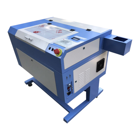
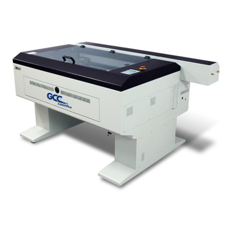
GCC Technologies LaserPro X252 User manual

www.technologysupplies.co.uk
content visit -
drivers and downloadable
For hints, tips, FAQ’s,
4eussI
User Guide - X252 & X380
e strongly recommend that you read and/or print out that manual.Wmachine.
This can be found on the GCC CD ROM, supplied with yours user manual.’rconjunction with the manufacture
a manual. It should therefore be read inThis document is designed as a quick step training guide and NOT
2021

Page 2
WF-Education has a comprehensive sevice and maintenance package ensuring your workshop equipment will last for future years. Trained engineers will
service and maintain the installed machinery and carry out all the obligatory fume and dust extraction tests (LEV). Please contact our Head Office for further
details of this service.
We can work in partnership with architects and designers to plan and produce workshop layouts complying with all relevant legislation and suggest quality
machinery and equipment that is fully compliant with all health and safety legislaton but is also relevant to the modern curriculum.
Manufacturers continuously improve their products and may modify the specification or look of their products without notice. We have tried to ensure the highest
accuracy to this manual at the time of publication.
Payment terms are nett monthly account. Please notify us of any shortages or damage within 3 days of delivery and in the case of non-delivery with 10 days
of the date of invoice. Any goods conveyed to customers remain the property of WF-Education group until paid for in full, but liability for those goods transfers
to the customer upon receipt. All business is transacted under our Terms and Conditions of Business, copies of which we are happy to supply upon request.
We accept orders by telephone, fax, post and email. We have no minimum order charge.
For secure on-line ordering please visit our website www.technologysupplies.co.uk
Orders are despatched within 1-5 days, unless school holidays intervene.
If an order is not complete when first despatched we do not charge carriage on the ‘to follow’ items. This does not apply to items such as large machines and
workbenches which have a longer lead time.
Please advise us if delivery cannot be made during school holidays.
WORKSHOP MAINTENANCE SERVICES
PLANNING & WORKSHOP LAYOUTS
INFORMATION IN THIS MANUAL
TERMS OF SALE
CATALOGUE ORDERS
ORDER DELIVERY

Page 3
4. . . . . . . . . . . . . . . . . . . . . . . . .Warranty Information
5. . . . . . . . . . . . . . . . . . . . . . . . .General Laser Information
6. . . . . . . . . . . . . . . . . . . . . . . . .What Materials Can Be Used?
7. . . . . . . . . . . . . . . . . . . . . . . . .Risk Assessment For Schools
9. . . . . . . . . . . . . . . . . . . . . . . . .General Maintenance
10. . . . . . . . . . . . . . . . . . . . . . . .Location Of The X252/X380 Mirrors
14. . . . . . . . . . . . . . . . . . . . . . . .Cleaning The Mirrors And Lens
17. . . . . . . . . . . . . . . . . . . . . . . .Laser Driver Installation
18. . . . . . . . . . . . . . . . . . . . . . . .Pre Installation Setup For Windows 8/10
19. . . . . . . . . . . . . . . . . . . . . . . .Driver Installation for Windows 7-10
20. . . . . . . . . . . . . . . . . . . . . . . .Recommended Driver Setup
22. . . . . . . . . . . . . . . . . . . . . . . .Techsoft 2D Design Version 2 Setup
24. . . . . . . . . . . . . . . . . . . . . . . .Example Project Using 2D Design Version 2
28. . . . . . . . . . . . . . . . . . . . . . . .How To Engrave A Photograph Using 2D Design
30. . . . . . . . . . . . . . . . . . . . . . . .CorelDraw Setup For Lasers
36. . . . . . . . . . . . . . . . . . . . . . . .Example Project Using CorelDraw
39. . . . . . . . . . . . . . . . . . . . . . . .How To Engrave A Photograph Using CorelDraw
42. . . . . . . . . . . . . . . . . . . . . . . .Setting Up The Laser Machine
44. . . . . . . . . . . . . . . . . . . . . . . .Setting Up The Printer Driver To Send A File
49. . . . . . . . . . . . . . . . . . . . . . . .Using The Rotary Attachment
53. . . . . . . . . . . . . . . . . . . . . . . .Page Setup For Rotary Attachment Using CorelDraw
54. . . . . . . . . . . . . . . . . . . . . . . .Printer Driver Setup For Rotary Attachment
55. . . . . . . . . . . . . . . . . . . . . . . .Manual Focus Probe
56. . . . . . . . . . . . . . . . . . . . . . . .Useful Control Panel Commands
57. . . . . . . . . . . . . . . . . . . . . . . .How To Enable/Disable The SMART Guard
58. . . . . . . . . . . . . . . . . . . . . . . .Maintenance Log
59. . . . . . . . . . . . . . . . . . . . . . . .X252 / X380 Engrave Settings
61. . . . . . . . . . . . . . . . . . . . . . . .Personal Material Settings Sheet
60. . . . . . . . . . . . . . . . . . . . . . . .X252 / X380 Cut Settings
Page
16. . . . . . . . . . . . . . . . . . . . . . . .Water Chiller Information
26. . . . . . . . . . . . . . . . . . . . . . . .How To Assign Colours In 2D Design
62. . . . . . . . . . . . . . . . . . . . . . . .Laser Setup Check List

Page 4
Your WF-Education Group Laser and tube are warrantied against manufacturing defects for a period of 2 years from the date of purchase, this warranty excludes any consumables
items. Subject to the terms and conditions listed below, the warranty will provide for the on-site repair of the laser, or any component thereof, which is identified as faulty or
below standard, or is a result of inferior workmanship or materials.
- The warranty shall only apply to defects that occur within the 2 year period (12 months on the laser tube).
- Any repair must be carried out by an authorised service technician - any unauthorised work will invalidate the warranty.
- The warranty does not cover any faults or defects caused by accident, misuse, fair wear & tear, neglect, tampering with the equipment, or any
attempt at adjustment or repair other than through WF-Education Group. Non-warrantied repair visits are chargeable at the current
technicians rate.
- If you experience difficulty using the product, please firstly refer to this manual, if the information you require is not avaliable in the manual then
please visit the laser FAQ section on our website www.technologysupplies.co.uk If you are still unsuccessful then phone the Technology Supplies
Technical Line for support (please see bottom of this page).
- In the unlikey event of a defect occurring, please phone WF-Education technical Line to arrange a technician’s visit.
- Becasue of the nature of the product, if your laser needs repair after the warranty period, the repair must only be carried out by an authorised
service technician. Further damage to the machine and also risks to health may occur when working with laser cutters if correct procedures and
parts are not used.
- In the event of a defect occurring, please first contact the WF-Education technical Line who will attempt to resolve or determine the issue prior to
arranging for a laser engineer to attend.
These are items that either have a limited life or their life is directly affected by their use, maintenance and care taken with them. For example the filters in the extraction units
have a limited number of hours before becoming clogged and are therefore not covered by any warranty.
The following items are classed as consumables and are not covered by the warranty.
* Fume Extraction Filters * Grid bed * Gas Struts for Lid
* Lens & Mirrors (their life is dependant on cleaning and maintenance) * Autofocus Probe and connecting components
WF-Education includes unlimited support throughout the life of the laser cutter.
1) The latest drivers, and FAQs, along with updated manuals are published via our website www.technologysupplies.co.uk
2) Telephone Support via our Technical Line on 01743 812200, option 2, one of our dedicated technical team members will be happy to help with your enquiry.
The Conditions of this Warranty are;
Within the 2 Year Warranty Period;
Outside the Warranty Period;
Consumables;
Total Product Technical Support;
Warranty Information
Page 5
General Laser Information

What is LASER an Abbreviation of?
LASER stands for Light Amplification by Stimulated Emission of Radiation.
How Does a Laser Work?
A CO laser works by exciting the molecules of a carbon dioxide gas mixture. C0 lasers are not powerful enough to mark or cut metal. The laser beam is focussed
22
through a lens and is so intensive that the beam can vaporise a wide range of materials. If the beam passes over the material quickly an engraved image is produced. By
slowing the speed down, the beam has time to vaporise more of the material resulting in a cut right through.
Laser Safety
The safety rating of Class 1 by CDRH means that the laser beam is enclosed in a cabinet and has safety interlock mechanisms to protect the operator from injury. When a
Class 1 laser system is equipped with a red dot pointer which allows you to accurately position the laser beam, the safety rating turns into a Class 3a due to the red beam
being laser light. This is similar to the laser pointing devices often used for presentations. The main safety precaution to be observed is to avoid placing your eyes in the
red beam path. This is difficult given the design of the laser cabinet.
The Conditions of this Warranty are;
2) Wear appropriate safety goggles especially when engraving with mirrors or coated .muinimuladesidonadnassarbdellemanesahcusslatem
).dradnatssadedivorperaselggoGytefaS(
.moordetalitnevllewanidesuebdluohsenihcamehT.desuebsyawladluohsdnadeilppussimetsysnoitcartxeemuFA)3
4) Always read the manual and caution labels carefully before operation.
.EFTPdnanolfeT,CVPsahcus,secnatsbuscixotecudorpyamtahtslairetamrehtorosecafrusevitisnestaeh,slatemevitcelferhtiwkrowtonoD)5
1) Do not attempt to modify or disassemble the laser system at any time as invisable laser radiation may cause physical burns or severe eye damage.
N.B. PVC, Plastazote, Teflon and some Styrenes produce corrosive fumes that will damage the mechanics of the laser, invalidate your
warranty and will be harmful to health. The user is responsible at all times for the health and safety of themselves and the people around
the machine with regards to the chosen materials.
! !
DO NOT PROCESS IT IN THE LASER!deniatrecsaebtonnaclairetamehtfoerutanehtfI)6
.semitllatadnahnoelbaliavaebdluohsrehsiugnitxeerifA)7 OC 2
.noitarepogniruddednettanuenihcamehtevaelreveN)8
enihcamruoytahterusnelliwti,yltneiciffeevargnednatucotuoyelbanesihtlliwylnotoN.metsysruoygninaelcdnagniniatniamrofsnoitadnemmocerehtwolloF)9
runs safely as well.
1) When cutting materials that can easily catch fire, such as acrylic, wood, paper or card it is VITAL that you have the air assist compressor turned on to prevent flames.
.taehdeppartehtdnamaebresalehtfoegassapwolsehtoteuderifno
.gnikrowsitinehwdednettanutfelNOT
sienihcamehttahtdesivdaylgnortssitI)3
Do not leave any material/debris underneath the laser grid bed or table otherwise when the laser is running the waste material below can be set
2)
Fire Prevention

Page 6
WF-Education always recommends that you consult your MSDS (Material Safety Data Sheet) supplied with your material, even if the material is listed
below as acceptable to be used with your laser. This is because certain materials may contain different chemicals/substances from the manufacturing process.
The user is responsible at all times for the health and safety of themselves and the people around the machine with regards to the chosen materials.
A WF-Education laser cutter with a Co2 laser tube can only process non-metal material, by etching or cutting.
Acrylic Veneer
Anodized Metals #Fabrics Painted Materials
Bamboo
Balsa Greyboard
Cardboard
Ceramics #Kevlar
Vinyl (GEFF)
Plastazote Plastazote
Below is a list of ‘known’ materials which are to be used in the laser cutter as they will produce corrosive fumes that will be harmful to health, damage theNOT
mechanics of the machine and invalidate the warranty.
Material
PVC - This material is extremely toxic, the resulting fumes will pass through most extraction filters.
PTFE
Teflon
Metals
Styrenes (modelling foam board, Styrofoam)
PVC based Vinyls
!
Boxcard
HIPS
Silicon Stone
Slate #
Ply
MDF
Polypropylene
Correx
Wood
Painted Metals #
Rubber
Pressboard
Tile #
Leatherette
Marble #
Matte Board
Melamine
Mylar
Nylon
Glass #
Non PVC Foam
Fiberglass
Composities Cork
= Engraving only (cannot be laser cut)#
Consult Your MSDS
Safe Materials to Use in the Laser
Materials NOT to Use in the Laser
!
What Materials Can Be Used?

Page 7
! !
Risk Assessment for Schools
The following risk assessment is provided to cover the use of laser cutters/engravers in schools to cut plastics, rubber, wood, card and textiles as an example of CAD/CAM.
It has been formatted in the style of CLEAPSS. Please note that all of the laser cutters supplied by Technology Supplies are Class 3a lasers (Class 1 without the red beam
pointer) not Class 4. The information gathered here assumes a worst case scenario with regard to the use of a laser cutter and highlights the general risks that could be
encountered.
Class 4 lasers must never be used in schools but, when enclosed, the classification of the whole system is reduced to class 1, which is acceptable. Many models incorporate
a low-power, visible (red) beam alongside the invisible, high-powered cutting beam. Whenever the machine is in operation, it must be assumed that where ever the visible
red beam is seen on the material, the invisible one is also present.
Burns Provided the laser beams are totally enclosed (reducing the hazard class of the system to 1), this risk is minimal.
Blinding Provided the laser beams are totally enclosed (reducing the hazard class of the system to 1), this risk is minimal.
High Voltage Provided the electrical supplies to the tube are totally enclosed, this risk is minimal.
Toxic Fumes PVC and polyurethane foams present a serious risk. Some plastics, rubber and MDF can give rise to harmful fumes.
- An interlock if fitted to all models to prevent access to the working area during laser operation whilst the laser is firing. The interlock system will also not
allow the laser to be fired without the extraction unit on. This device is essential and it must not be over-ridden.
- Servicing MUST only be carried out by a manufacture authorised and trained technician to control the high voltage risk as well as risks from the beam.
- PVC and polyurethane foams should not be cut even with LEV in use.
PVC, PTFE, Plastazone, Teflon and some styrenes will produce corrosive fumes that will be harmful to health, damage the mechanics of the
machine and invalidate the warranty. The user is responsible at all times for the health and safety of themselves and the people around
the machine with regards to the chosen materials.
Burns Class 4 (high-power) lasers can cause severe burns to skin.
Blinding Class 4 lasers can cause blinding if a reflected beam enters the eye; the invisible infra-red radiation from a Co2 laser renders the cornea of the eye
opaque in a fraction of a second.
High Voltage The gas filled tubes used as the source of the radiation operate at hazardous live potentials.
Toxic Fumes The use of the laser to cut PVC generates toxic vinyl chloride and other decomposition products. Polyurethane foams may give hydrogen cyanide
and nitrogen oxides when heated by the beam.
Harmful Particles The cutting process releases fine particles and decomposition products from the materials being cut. Rubber will produce a mixture of pyrolysis
products, including some harmful ones.
General Information
Hazards
General Information
Control Measures

Page 8
!!
Combined
HEPA/Carbon
Filter
The beam may produce a deep cut in tissue with little bleeding because the wound is immediately cauterised. Obtain specialist treatment.Burns
There is no immediate remedial measure.Blinding
Taking care for your own safety, break contact by switching off or pulling out the plug. If it is necessary to move the casualty without switchingHigh Voltage
off the supply/use a broom handle or wooden window pole or wear rubber gloves. If the casualty is unconscious and not breathing, check that
the airways are clear and begin artifical ventiltion. Send for an ambulance. If a trained first aider does not arrive quickly and the pulse is absent,
consider carrying out resuscitation.
Remove casualty to fresh air and seek medical attention.Toxic Fumes
If dust is in the eye, irrigate immediately and with water for several minutes, telling the casualty to hold eyelids apart.Harmful Particles
In order to meet the requirements of the COSHH Regulations for LEV, the school must operate a strict regime of
filter replacement and/or testing.
Pre-filters, which collect the coarse/solid particles, may need changing every couple of months. The main filter,
which is a combined activated carbon and HEPA filter which is for fine particles and odour, may last six months
to a year (all depending on material & usage).
The latest extraction units are equipped with air flow warning devices to aid the monitoring of efficient filter life.
Please refer to the separate section within the manual.
We recommend that a record of filter life is kept over the period of ownership. This will ensure that a school can
build a service/maintenance record according to HSE guidelines.
The fume and dust-control systems must be properly maintained, tested annually and the filters changed according to the manufacturer’s instructions. Used filters should
be sealed into a strong plastic bags before placing them in the waste, please take care to wear the appropriate PPE clothing when dealing with the contaminated filters.
Pre-filter
Laser cutters should be stored in secure locations to prevent un-authorised use.
We recommend that they are used only by teachers/technicians that have undertaken suitable training in the use of these machines.
Laser cutters should NOT be left unattended during operation due to risk of fire.
Immediate Remedial Measures
Extraction & COSHH Information
Disposal of Extraction Filters

Page 9
!!
General Maintenance
The lens, mirrors, bed, auto-focus gauge and runners must be cleaned before use or on a weekly basis to ensure correct operation of the laser, and the fume extractor
filters should be replaced as required. If you cut and/or engrave mainly on wood, MDF and plywood then more fumes are produced therefore the lens, mirrors, will need
cleaning much more frequently, (Please refer to the maintenance log on page 57).
Please refer to the manual supplied on CD with your extraction for operating and maintenance instructions.
When laser cutting, waste material builds up under the cutting table and must be removed on a regular basis and cleaned out as this can be ignited by the laser.
Especially when wood and card waste are present as they can be ignited more easily.
To clean the waste, lower the bed and remove the grid bed, open the front door panel and then sweep the bed area clean. Any staining on the bed can be removed
with cream cleaners such as Cif on a damp cloth and then dried. Ensure that the machine is disconnected from the mains power.
These are the most important parts of the laser for ensuring efficient cutting and engraving operations. If there is any sign of dirt or marks on any of these, the lasers power
and cutting efficiency will decrease. Only use the manufacturer’s recommended cleaning materials.
The mirrors in your laser cutter are numbered in the order they get hit by the laser beam. See
picture on the right for a visual reference of the mirrors. Please note the X380 laser machine has
4 mirrors, whereas the X252 laser has only 3 mirrors.
Keeping the optics and motion system clean is essential for excellent quality engraving and for the reliability of your engraver.
Please clean the bearing tracks and x-axis bearing daily to maintain good condition of the machine.
Never pour or spray any liquid directly onto the laser system.
Turn off the power and disconnect from the mains before carrying out any internal cleaning.
Mirror 1 Mirror 2 Mirror 3 Mirror 4
Fume Extractor Unit
General Maintenance
Mirrors & Lenses
Identifying the Mirrors

Page 10
Step 1. To access mirror 1 you will need to remove the screws from the tube access panel. Accessing this panel will reveal the black casing which contains mirror #1.
N.B. PLEASE MAKE SURE THE LASER MACHINE IS DISCONNECTED FROM THE MAINS POWER BEFORE OPENING THE TUBE ACCESS PANEL!
Step 2. Simply remove the screws as shown below, this will then allow you to slide the black dust cover off the mirror 1 housing.
Remove these three screws to open the
laser tube access panel.
Black Casing
Accessing Mirror 1
Location of the X252/X380 Mirrors

Page 11
Besides Mirror 1, the other mirrors 2, 3 and the lens are located in the main chamber of the laser cutter. Below is a photograph of the main chamber of the laser with the
locations of where each mirror and Lens can be found. Mirror #2 is on the left of the arm, mirror three is inside the head along with the lens.
Step 4. With the dust cover removed you will be able to see 2 mirrors (A & B). Mirror A is the Red Beam mirror and only has to be cleaned if you can no longer see the
red beam on the laser bed/material, as this mirror only bounces the red light beam NOT the laser cutting beam.
The mirror labelled B is mirror number one which is the first of the three mirrors which the laser beam hits as it passes through the machine.
To remove this for cleaning simply loosen the two thumb screws and slide the mirror out.
A
B
Accessing Mirrors 2, 3 and the Lens
Mirror #2
Loosen the 2 thumb screws
and slide mirror #1 out
Red laser pointer beam generator.
Mirror #3
and focusing
lens

Page 12
Releasing Mirror #2 (Mirror #3 on the X380)
Accessing Mirror #3 (Mirror #4 on the X380)
To release this mirror you need to loosen off the two screws as shown below and slide the mirror out. Ensure that the mirror is replaced correctly before reassembly.
As shown below, to be able to access the lens and mirror #3 (mirror #4 on the X380) for cleaning you need to release the front cover. To do this you need to remove
the bottom two screws, and loosen off the top screw. This enables you to swing the cover over and gives access to slide the items out. Ensure that the mirror and lens
are replaced correctly
before reassembly.
Loosen off these
two screws to
enable you to
slide out the
Mirror
Loosen off this
top screw and
swing the cover
around clockwise
Note:
Mirror #3
(mirror #4
on the
X380)
To remove mirror
#3 (#4) for cleaning
you will need to
loosen the screw
above the mirror
located at
2 inch
Focusing lens
Remove these
two screws and
store in a safe
place

Page 13
Correct Positioning of Mirror #3 (Mirror #4 on the X380) and the 2 Inch Lens
A common problem for first time users is that after cleaning they insert the mirror and the lens into the wrong locations. Please see pictures below explaining how to locate
these parts correctly.
Mirror #3 / #4 location
This mirror will locate above the two
small arms inside the laser head.
Lens location
The 2 inch lens will locate directly above the
two screw holes on the head.

Page 14
The mirrors should be cleaned on a weekly basis or daily basis depending upon usage. The mirrors are gold faced and can easily be damaged if not handled carefully.
The mirrors can blister and crack if they are not kept clean. When cleaning always put the mirrors with the gold face uppermost and only use the proper cleaning materials.
(See Photo in step 1). Kodak lens cleaning fluid and special lens cleaning papers are provided with the machine for this purpose. Spares are available from our website.
Step 3. Support the mirror to prevent it moving during cleaning, and holding the dry end, slowly drag the paper cloth across the mirror’s surface as show below.
If the mirror is dirty you may have to repeat this process several times with a new paper each time. The fluid will evaporate leaving a clean and shiny surface. After a
period of time, a film of cleaning fluid will build up on the surf ace of the mirrors. Under these circumstances, it will be necessary to use a complete cleaning sheet,
folded into a pad. Drop a spot of fluid onto the cleaning paper and then apply A REASONABLE PRESSURE with your finger as you drag it across the surface of the mirror.
Mirror - Gold
Surface facing
up
Cleaning The Mirrors And Lens
Cleaning the Mirrors
Step 2.Tear off a 20mm wide strip of cleaning paper, lay one end on the mirror and squeeze one or two drops of cleaning fluid onto it. IMPORTANT - USE ONLY THE SPECIFIED
CLEANING PAPER FOR THE MIRRORS - DO NOT USE THE CLEANING SWABS.
Step 1. Place the mirror gold side up on the side of the laser cutter or on a clean surface.

Page 15
Auto Focus Guage -
ensure the brass
plunger has free
movement and is clean
by gently pushing the
plunger upwards and
seeing if it springs back.
The lens should be checked often and cleaned, possibly hourly especially if you are processing materials which contain resin such as woods, MDF and ply.
Squeeze some lens cleaning fluid onto a cotton swab and gently rub in a spiral motion from the centre outwards on both sides of the lens.
If necessary dry the lens with a clean dry swab. If the lens is not totally clean then instead of the laser light transmitting through the lens it can heat up the glass and
cause expensive damage.
Clean this every time the machine is used by wiping the brass plunger
with a cloth to ensure it is free to move up and down.
The gantry arm, motion system track and V shaped carriage wheels
need to be wiped with a clean dry cloth daily to ensure smooth movement
of the laser head.
If you notice a build up of dirt within the wheels then you can simply insert
a cotton bud into the groove of the wheel/gantry and manually move
the head back and forth to clean out the dust particles.
DO NOT apply grease or oil to the motion system tracks.
The grid bed (cutting table) will over time take on a black stained appearance around the area most used for cutting. In most cases this will be localised around the top
left hand quarter. You may also find that you will start to get an odour from the machine itself during and after processing. We have found
from experience that the following procedure does dramatically clean up the grid bed, but the process may need to be repeated to get a good results.
Step 1 : Obtain a trough big enough to accept the grid bed, which is water tight or (use bricks and a sheet of plastic, outdoors).
Step 2: Dissolve mild detergent into warm water in your trough.
Step 3: Place the grid bed face down (so that the rubber feet are sticking out of the water) and leave to soak for 24 hours (or preferably a weekend).
Step 4: Thoroughly dry off the grid bed before use. You may have to repeat a couple of times to get rid of the majority of the staining.
Disclaimer: WF-Education can take no responsibility for any damage to the grid bed.
Degradation of rulers and paintwork will ensue if using detergents and other fluids to clean the cutting surface.
Cleaning the Laser Grid Bed
Cleaning the Gantry Arm & System Tracks
Cleaning the Auto Focus Gauge
Lens Cleaning

Page 16
It is essential that you drain your chiller and replace the water a minimum of every 3 months. Disconnect the pipes from both units and drain excess water
into a suitable container to reduce unit weight. To completely drain all the water from the chiller, place the unit in/over a sink and remove the draining cap
(indicated in the diagram below).
Once the water has completely drained from both the chiller and laser then you can attach the water pipes correctly to the chiller and laser cutter.
Undo the screw cap on the top of the water chiller and fill with your new de-ionised water up to the required level.
Temperature Indicator
Warning Light
Safe running light
Outlet pipe connection
On/Off power switch
HHooww Offtteenn Doo Yoouu Chhaannggee Yoouurr Waatteerr??
Inlet pipe connection
Draining cap
Cooling fan
Power cable insert
CW3000 Chiller Unit (7-8 litres)CW5000/5200 Chiller Unit (6-7 litres)
Water Chiller Information
WWhhaatt Tyyppee ooff Watteerr Dooeess tthhee Chhiilllleerr Reqquuiirree??
You should only use de-ionised water in the chiller unit. This is becasue de-inoised water reduces electrical conductivity and also reduces mineral deposits
on the chillers internal components. Changing the water regularly will aid the lifetime of the water chiller. De-ionised water can be purchased from most
automotive shops such as Halfords etc.
Filling cap

Page 17
Please note that most modern lasers will no longer have the USB Setup Wizard option, as parallel setup is no longer available,
in which case ignore the 5 steps below and proceed to the relevant driver installation page.
The latest laser printer driver is usually in the form of an executable installation program and therefore only requires double clicking to install.
However sometimes the driver can contain a directory of 9 files, including an inf file in which case please follow the step by step installation on page 18.
Laser driver setup from the executable file (windows 7, 8 & 10), please refer to page 18.
Step 1. Before installing your Windows driver you may need to change the USB Setup Wizard in the laser control panel. To do this turn the laser cutter ON and wait for
it to finish initialising, once it has finished Press F4 (Function, on the laser main menu control panel).
Step 2. In the next screen you will see a black diamond to the left hand side of your options. Move the diamond using the up and down directional keys either side
of the enter button on the control panel, navigate to the option, Machine Settings and press Enter.
Step 3. Again using the up and down controls, scroll through the options and select USB Setup Wizard and press Enter.
Step 4. The laser USB is usually set by default to GCC USB. You will need to press the right arrow (by the enter button) this will now show either Common, Windows
or Vista depending on your firmware. Once one of these options appears on your control panel screen press F4 to save the option.
Step 5. Now press F1 (back) until you reach the Empty File screen.
Windows 10 does not allow the installation of unsigned drivers, please refer to page 17 for information on disabling this function and to boot around Windows start up.
Before you start :-
Laser Driver Installation

Page 18
Step 1.
Step 2.
Step 3.
Step 4.
Many devices ship with unsigned drivers and 64-Bit versions of Windows require digitally signed drivers. Digitally signed drivers include an electronic fingerprint that indicates
which company the driver was produced by, as well as an indication as to whether the driver has been modified since the company released it. The laser drivers are NOT digitally
signed and therefore may require this workaround.
Pre-Installation for Windows 8/10 driver
To disable driver signature verification, go to the troubleshooting options from the boot manager.
The easiest way to bring this screen up is by selecting, restart from the power options menu
(on Windows 8 it’s under Charms or on the login screen, and in Windows 10 it’s on the Start Menu).
Hold down the SHIFT key while you click Restart.
Once your computer has rebooted you will be
able to choose the Troubleshoot option.
Head into Advanced options,
then choose Start-up Settings.
Since we are modifying boot time configuration settings, you will need to restart your computer one last time.
Finally, you will be given a list of start-up settings that you can change. The one we require is
“Disable driver signature enforcement”. To choose this setting, you will need to press the F7 key.
Your PC will then reboot and you will be able to install unsigned drivers without any error message.
Pre-Installation Setup for Windows 8/10

Page 19
Step 1. Insert the LaserPro driver CD supplied with your laser cutter and close the auto disc startup feature.
Insert the LaserPro driver GCC CD disc supplied with your laser cutter.
Close the auto disc startup and navigate to the laser drivers folder e.g. GCC Disc\X252\LaserPro Driver\*.EXE
Double click the required file and this will install automatically. When this has fininshed, close the small install window.
Step 2.
Step 1.
Step 2.
Step 3.
Go to the Start menu within Windows 7 and select Devices and Printers. Then select Add a Printer from the top toolbar.
Step 3. Select add as a Local Printer and click OK.
Step 4. Select USB001 (Virtual Printer Port for USB) from the “use an existing port” drop down menu, then click Next. If the USB 001 option is not available,
remove the USB cable from the computer and re-plug it in and start again from step 2.
Step 5. Select Have Disk, then select Browse.
Step 6. Now select your Windows 7 printer driver from your Laser Pro CD and keep on clicking through the menus until you reach the driver, select ‘Do Not Share’ and
‘Do Not Print A Test Page’
Step 7. Click OK, then Select Next.
Step 8. Then select Next and then click OK.
To test that the machine is connected correctly you should go back to the devices and printers section in Windows. You will first see an unspecified device at the
bottom of your screen and you will also see your laser cutter printer driver in the printers section just above this. If you now unplug the USB cable from the computer
the unspecified device will disappear and your laser printer should grey out on the screen (to indicate it has gone offline). If the printer driver has been installed successfully
then when you reconnect the USB cable back into the computer (correct USB port) the unspecified device will reappear and you should see the printer driver become
bold again (come back online).
Installation Complete
Installing Windows 7 Driver (inf file)
Installing Windows 7-10 Executable Driver File
How to Test Your Windows Installation
Installing Windows 7/8 USB driver
Note: After installation using this method please ensure the port for the printer driver is set to USB001 virtual port.
The laser driver is USB port specific once installed.
Driver Installation For Windows 7-10

Page 20
This simple step by step guide is provided to set your machine up for best use within the education sector. By following the guide you will be running your printer driver
in conjunction with the recommendations of WF-Education Group. The settings will reduce users experiencing issues with educational specific software (such as 2D Design).
Please perform this setup under FULL ADMINISTRATION RIGHTS.
Step 1. Go to the Windows start button in the bottom left hand corner of Windows.
Then go to Devices and Printers (Windows 7).Step 2.
Right click on your laser cutters printer driver and select properties at
in the drop down menu (it will be printer properties on Windows 7).
Step 3.
. The printer properties window will now open. Go to the Ports tab and set the laser driver to the USB virtual port (refer to image below left).Step 4
Laser Driver Setup
. Go to the first of two tabs and set the option calledStep 5 Advanced Print directly to printer (refer to image below right).
Windows 7 View
X252
Recommended Driver Setup
This manual suits for next models
1
Table of contents
Other GCC Technologies Engraver manuals

GCC Technologies
GCC Technologies LaserPro C180 User manual

GCC Technologies
GCC Technologies LaserPro C180II User manual

GCC Technologies
GCC Technologies LaserPro SmartCut X380 Series User manual

GCC Technologies
GCC Technologies LaserPro DFS User manual

GCC Technologies
GCC Technologies LaserPro Venus II User manual

GCC Technologies
GCC Technologies S290LS Series User manual

GCC Technologies
GCC Technologies LaserPro S400 User manual

GCC Technologies
GCC Technologies LaserPro Spirit Series User manual

GCC Technologies
GCC Technologies LaserPro E200 Series User manual

GCC Technologies
GCC Technologies StellarMark 3DS User manual