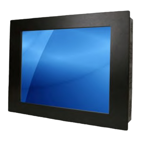
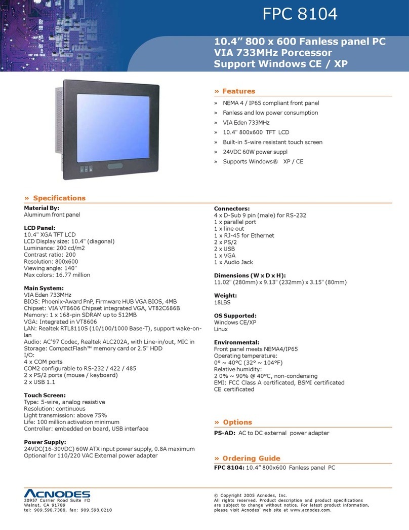
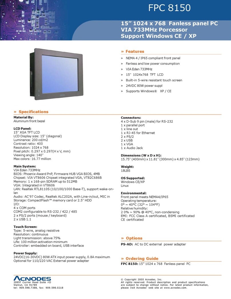
Acnodes PCM8210 User manual

User Manual
All rights reserved. Product description and product specifications are subject to change without
notice. For lastest product information, please visit Acnodes’ website at www.acnodes.com
14628 Central Ave. Chino, CA91710 Tel: 909.597.7588 Fax: 909.597.1939
© Copyright 2020 Acnodes Corp.
PCM8210PCM8210
10.4" Industrial Panel PC
5th Gen. Core i5 5200U 2.2GHz CPU
Full IP67 Rated Enclosure
Embedded Computers

1
IMPORTANTSAFETY INSTRUCTIONS
1.
Please read these instructions carefully before using the product and save for later reference.
2.
Follow all warnings and instructions marked on the product.
3.
Our military devices complied to ITAR –FREE for import/export to US territory.
4.
All products comply to ROHS and REACH regulation.
5.
No halogen or toxic metal contains or generated toxic material in use.
6.
Cleaning notice: the product with a damp soft cloth. Do not use liquid or aerosol cleaners as it may cause
permanent damage to the screen.
7.
Do not use this product near water.
8.
Do not place this product on an unstable cart, stand, or table. The product may fall, causing serious damage
to the product.
9.
Slots and openings in the cabinet and the back or bottom are provided for ventilation; to ensure reliable
operation of the product and to protect it from overheating, these openings must not be blocked or covered.
The openings should never be placed near or over a radiator or heat register, or in a built-in installation unless
proper ventilation is provided.
10.
This product should be operated from the type of power indicated on the marking label. If you are not sure
of the type of power available, consult your dealer or local power company.
11.
Do not allow anything to rest on the power cord. Do not locate this product where persons will walk on the
cord.
12.
If an extension cord is used with this product, make sure that the total of the ampere ratings on the
products plugged into the extension cord does not exceed the extension cord ampere rating. Also make
sure that the total of all products plugged into the wall outlet does not exceed 15 amps.
13.
Never push objects of any kind into this product through cabinet slots as they may touch dangerous voltage
points or short out parts that could result in a risk of fire or electric shock. Never spill liquid of any kind on the
product.
14.
Do not attempt to service this product yourself, as opening or removing covers may expose you to dangerous
voltage points or other risks and will void the warranty. Refer all servicing to qualified service personnel.
15.
Unplug this product from the wall outlet and refer servicing to qualified service personnel under the following
conditions:
-
When the power cord or plug is damaged or frayed.
-
If liquid has been spilled into the product.
-
If the product has been exposed to rain or water.
-
If the product does not operate normally when the operating instructions are followed. Adjust only those controls
that are covered by the operating instructions since improper adjustment of other controls may result in damage
and will often require extensive work by a qualified technician to restore the product to normal operation.
-
If the product has been dropped or the cabinet has been damaged.
-
If the product exhibits a distinct change in performance, indicating a need for service.

2
CAUTION
Read manual prior to installing the product. The operation of products depends on you reading
and following the information in this manual. Re-check your work prior to operating the product.
EVENT
EFFECT
PREVENTION
Sunlight shines directly will
cause the panel damage.
You should avoid placing the
product under direct sunlight.
If the product is close to the
wet ground such as grassplot,
the moisture between panel
and glass will make the
productmalfunction.
For None-IP level proof
models, please do not
splash water or put into
water from all direction.
Avoid settling the product
close to fire or explosive zones
All components comply to LFH
definition, no toxic fumes
generated when the device
put in the fire
Products comply to ROHS and
REACH regulations

3
Contents
REVISION HISTORY.................................................................................................. 2
IMPORTANTSAFETYINSTRUCTIONS.................................................................. 1
Contents......................................................................................................................... 3
1.1.
About the Rugged display............................................................................ 4
1.2.
Notice.......................................................................................................... 4
1.3.
Order Option............................................................................................... 4
1.
Input / OutputOverview........................................................................................... 5
1.1.
For Non-Military Connectors........................................................................ 5
1.2.
Typical Type................................................................................................ 5
1.3.
Military (D38999) Type................................................................................ 6
2.
Using the LCD Monitor............................................................................................. 8
2.1.
OSD Key Definition...................................................................................... 8
2.2.
OSD Hot Keys (Auto).................................................................................. 9
2.3.
OSD Menu Navigation................................................................................. 9
4.
Disclaimer ............................................................................................................. 14
5.
Troubleshooting..................................................................................................... 15

4
1.
Getting Started
1.1.
About the Rugged display
This rugged product adopts a high quality TFT LCD panel. (Options for high brightness, optical bonding
features.) It is designed to fit to the harsh environment and requirements of today’s business in the
heavy duty / military applications.
The model can separatedto 2 categories:
Basic Configuration: Standard Connectors / Front IP65
Advanced Configuration: D38999 Connectors / Full IP65 orIP67
Besides, there would be more advanced options on LCD displayor on its specifications.
1.2.
Notice
a.
Do not touch the LCD panel surface with sharp or hard objects.
b.
Do not use abrasive cleaners, waxes or solvents for cleaning, use only a dry or damp, soft
cloth.
c.
Use only with a high quality, safety-approved,AC/DC power adapter.
If any items are missing or damaged, please contact your dealer immediately.
1.3.
Order Option
a. LCD
Brightness Enhancement
1,000 nits sunlight readable high brightness
Touch Screen
5-wire resistive touch
Optical Bonding
Optical bonded by panel and touch or glass
b. Protective Glass
AR protective glass
Anti-reflective glass in front
ITO coating glass
ITO conductive glass for MIL-STD-461F
Heater glass
Heater glass for low temperature (-40degC)
Mesh filter
Mesh filter for MIL-STD-461F
c. Connectors
MIL. connectors
D38999 MIL. connectors
Connector Position
Down side or Bottom side
USB Port
USB TypeA port for USB Drive
d. System Protection
Heater Board
Heater board for low temperature (-40degC)
Wide range DC Input
9~36V DC Input (reversed current protection)
IP Level
Full IP65 or IP67
With different option which might impact the parameter in the specification should be double
checked by your sales representative to acquire the correct parameter.
The major impact would be on, i.e. power consumption, LCD brightness, operating
temperature…etc.

5
1.
Input / Output Overview
1.1.
For Non-Military Connectors
The default output signal is VGA for the main display and S-Video for PIP display. The LCD
output can be configured to use any of the available input formats (VGA, DVI, S-Video, and
Composite).
1.2.
Typical Type
Power cable connection:
Connect the power cord to the AC outlet, and connect the power to the monitor through the AC/DC
adapter.
VGA cable connection:
Plug 15-pin VGA signal cable to the VGA connector in the rear of PC system, and plug the other end
to the monitor. Secure cable connectors with screws.
DVI cable connection:
Plug DVI signal cable to the DVI connector in the rear of PC system, and plug the other end to
the
monitor. Secure cable connectors with screws.

6
1.3.
Military (D38999) Type
Type A: Connectors at down side
The default signal is VGA (J2) and power input (J1)
J1: Power Input (D38999/24WA98PN)
Wide Range DC Input is default definition in military LCD monitors, connect the power cord to the DC
outlet, and connect the power to the monitor through pins as below
J2: Signal Pins (D38999/24WD35PN) (Default: VGA, Optional: VGA+DVI)
Default is VGA Input, with additional one DVI-D could be for optional.
J3: Video Input (BNC)
This is a BNC connector for NTSC/PAL video input signal.
J1
Power
A
VCC+
B
VCC-
J2
VGA
J2
DVI-D
J2 Pin
Pin Name
J2 Pin
Pin Name
1
ANALOG RED INPUT
15
RXC-1N
18
ANALOG GROUND
28
RXC+1N
2
ANALOG GREEN INPUT
33
GND
19
ANALOG GROUND
13
DVI 5V
3
ANALOG BLUE INPUT
23
GND
20
ANALOG GROUND
12
DVI CAB
4
DDC SERIAL DATA
11
DVI SDA
17
H-SYNC
10
DVI SCL
30
V-SYHC
35
RX0-IN
31
DDC SERIAL CLOCK
34
RX0+IN
21
DIGITAL GROUND-
24
GND
32
VGA DETECT
14
RX1-IN
27
RX1+IN
8
GND
25
RX2-IN
26
RX2+IN
9
GND

7
Type B: Connectors at Rear side
J1: Power Input (D38999/24WA98PN)
Wide Range DC Input is default definition in military LCD monitors, connect the power cord to the DC
outlet, and connect the power to the monitor through pins as below
J2: Signal Pins (D38999/24WD35PN) (Default: VGA, Optional: VGA+DVI)
Default is VGA Input, with additional one DVI-D could be for optional.
J3: Video Input (BNC) (Optional)
This is a BNC connector for NTSC/PAL video input signal.
USB: USB Connector for USB Type A Drive (D38999/USBFTV71G w/ cap)
J1
Power
A
VCC+
B
VCC-
J2
VGA
J2
DVI-D
J2 Pin
Pin Name
J2 Pin
Pin Name
1
ANALOG RED INPUT
15
RXC-1N
18
ANALOG GROUND
28
RXC+1N
2
ANALOG GREEN INPUT
33
GND
19
ANALOG GROUND
13
DVI 5V
3
ANALOG BLUE INPUT
23
GND
20
ANALOG GROUND
12
DVI CAB
4
DDC SERIAL DATA
11
DVI SDA
17
H-SYNC
10
DVI SCL
30
V-SYHC
35
RX0-IN
31
DDC SERIAL CLOCK
34
RX0+IN
21
DIGITAL GROUND-
24
GND
32
VGA DETECT
14
RX1-IN
Option
USB (for touch)
27
RX1+IN
5
D+
8
GND
6
D-
25
RX2-IN
7
Vcc
26
RX2+IN
22
GND
9
GND

8
2.
Using the LCD Monitor
2.1.
OSD Key Definition
There are two types OSD keypad,
Type A
Type B
POWER
Initiates power-up sequence from low power mode or enters low power mode from normal
operation.
AUTO
Perform Auto Adjustment
Esc (EXIT)
i.
When OSD is enabled, it returns to the previous menu level or closes the OSD.
OK/MENU (ENTER)
ii.
When OSD is disabled, it displays the OSD Main Menu.
iii.
When OSD is enabled, it confirms a selection.
LEFT
Moves left in the menu or bar
RIGHT
Moves right in the menu or bar

9
UP
iv.
Selects the previous item in the Menu.
DOWN
v.
Selects the next item in the Menu.
2.2.
OSD Hot Keys (Auto)
Function
Hot Key
Main source
Press “
”to select the main source
Volume
Press “
”to the volume bar, and press “ ” “ ”to adjust
the
volume
Autoadjustment
Press “AUTO” to perform auto adjustment
2.3.
OSD Menu Navigation
OSD menu
2.3.1.
Display
OSD icon
Sub menu
Settings
Note
BRIGHTNESS
slider bar
Adjusts the overall image and background brightness. Press “ ” or “ ” to adjust.
CONTRAST
slider bar
Adjusts the image brightness in relationship to the background. Press“ ” or “ ”to adjust.
SHARPNESS
slider bar
Adjusts the crispness of the image. Press“ ” or “ ” to adjust.
ADC BRIGHTNESS
slider bar

10
*VGA CHANNEL ONLY
Adjusts the ADC brightness. Press“ ” or “ ”to adjust.
COLOR TEMPERATURE
USER/6500K/9300K
Adjusts the color temperature of the entire screen. A low color temperature will make
The screen reddish. A high color temperature will make the screen bluish.
COLOR CONTROL
R slider bar
G slider bar
B slider bar
Y slider bar
M slider bar
C slider bar
Adjusts the levels of the Red, Green, Blue, Yellow, magenta, and cyan. Press“ ” or “ ” to
adjust.
GAMMA SELECTION
@NATIVE
@1.8
@2.2
Select a display gamma value for best picture quality.
SCHEME
USER
GAME
SPORT
VIVID
CINEMA
Select scheme for different default setting combination.
DISPLAY RESET
YES/NO
Resets the following settings within the DISPLAY menu back to factory setting:

11
2.3.2.
Adjust
AUTO SETUP
*VGA CHANNEL ONLY
PRESS YES TO AUTO SETUP
Automatically adjusts screen size, H position, V position, Clock, Clock Phase
AUTO ADJUSTMENT
*VGA CHANNEL ONLY
ON/OFF
H Position, V Position and Clock Phase are adjusted automatically upon power on.
H POSITION
*VGA CHANNEL ONLY
slider bar
Controls the horizontal position of the image within the Display area of the LCD.
Press + to move right. Press - to move left.
V POSITION
*VGA CHANNEL ONLY
slider bar
Controls the vertical position of the image within the Display area of the LCD.
Press + to move up. Press - to move down.
CLOCK
*VGA CHANNEL ONLY
slider bar
Press + to expand the width of the image on the right of the screen.
Press - to narrow the width of the image on the left.
PHASE
*VGA CHANNEL ONLY
slider bar
Adjusts the visual “noise” on the image.
WHITE BALANCE
*VGA CHANNEL ONLY
YES/OFF
Perform the white balance
SCALING
@ ASPECT
@ OFF
@ FULL
Adjust the image scaling setting
ADJUST RESET
YES/NO
Resets the following settings within the ADJUST menu back to factory setting:

12
2.3.3.
Audio
VOLUME
slider bar
Audio Input
slider bar
MUTE
ON/OFF
AUDIO RESET
YES/NO
Resets “AUDIO” settings back to factory settings.
2.3.4.
PIP (Picture in picture)
PIP SOURCE
VGA
DVI
Composite
S-Video
PIP MODE
@OFF
@LARGE PIP
@SMALL PIP
@SIDE BY SIDE ASPECT
@SIDE BY SIDE FULL
Selects the size of the sub-picture used in Picture-in-Picture (PIP) mode.
PIP POSITION
slider bar
slider bar
Determines where the PIP appears on the screen.
PIP RESET
YES/NO
Resets the following settings within the PIP menu back to factory setting
*PIP mode selection guide
X: not support V : support mode
Sub
Main
Composite
Video
S-Video
VGA
DVI
Composite
Video
X
X
V
V
S-Video
X
X
V
V
VGA
V
V
X
V
DVI
V
V
V
X

13
2.3.5.
OSD settings
OSD TURN OFF
slider bar
Turns off the OSD after a period of inactivity. The preset choices are 0-60 seconds.
OSD POSITION
H - slider bar
V - slider bar
Determines the location where the OSD appears on the screen.
OSD TRANSPARENCY
@OFF
@TYPE1
@TYPE2
set the transparency level of OSD
OSD Rotated
@OFF
@90
@270
Set to rotate the OSD menu
MONITOR INFORMATION
Version
Panel Resolution
Main Resolution
PIP Resolution
Show BIOS version & resolution info.
OSD RESET
YES/NO
Resets the following settings within the OSD menu back to factory setting
2.3.6.
Advancedsettings
CHANNEL SELECT
VGA
DVI
HDMI
DP
Select the input signal source
FLIP
@OFF
@H-FLIP
@V-FLIP
@HV-FLIP
Adjust the flip settings
BRIGHTNESS MIN
Slide bar
ADVANCED RESET
YES/NO
Resets the following settings within the ADVANCED menu back to factory setting
FACTORY RESET
YES/NO
Resets OSD options back to factory settings EXCEPT FOR: CHANGE SECURITY PASSWORD
and SECURITY PASSWORD.

14
3.
Cleaning the Monitor
1.
Make sure the monitor is turned off.
2.
Never sprayor pour any liquid directly on the screen or case.
3.
Wipe the screen with a clean, soft, lint-free cloth. This removes dust and other particles.
4.
The display area is highly prone to scratching. Do not use ketone type material (ex. Acetone),
Ethyl alcohol, toluene, ethyl acid or Methyl chloride to clear the panel. It may permanently
damage the panel and void the warranty.
5.
If it is still not clean enough, apply a small amount of non-ammonia, non-alcohol based glass
cleaner onto a clean, soft, lint-free cloth, and wipe the screen.
6.
Don’t use water or oil directly on the monitor. If droplets are allowed to drop on the monitor
permanent staining or discoloration may occur.
4.
Disclaimer
We do not recommend using any ammonia or alcohol-based cleaners on the monitor screen or
case. Some chemical cleaners have been reported to damage the screen and/or case of the
monitor. Seller will not be liable for damage resulting from the use of any ammonia or
alcohol-
basedcleaner.

15
5.
Troubleshooting
If your monitor fails to operate correctly, consult the following chart for possible solution before calling for repairs:
Condition Check Point
1. The picture does not
appear
Check if the signal cable is firmlyseated in the socket.
Check if the Power is ON at the computer
Check if the brightness control is at the appropriate position, not at
theminimum.
2. The screen is not
synchronized
Check if the signal cable is firmlyseated in the socket.
Check if the output level matches the input level of your computer.
Make sure the signal timings of the computer system are within the
specification of the monitor.
If your computer was working with a CRT monitor, you should check
the current signal timing and turn off your computer before you
connect the VGACable to this monitor.
3. The position of the
screen is not in the center
Adjust the H-position, and V-position, or Perform theAuto
adjustment.
4. The screen is too bright
(too dark).
Check if the brightness or contrast control is at the appropriate
position, not at the Maximum (Minimum).
5. The screen is shaking or
waving
Perform theAuto adjustment.
Moving all objects which emit a magnetic field such as motor or
transformer, awayfrom the monitor.
Check if the specific voltage is applied.
Check if the signal timing of the computer system is within the
specification of monitor.
6. VGAsignal got noise
when using PIP function
Change PIPmode again.
If you are unable to correct the fault by using this chart, stop using your monitor and contact your distributor or dealer for further assistance
Table of contents
Other Acnodes Touch Panel manuals

Acnodes
Acnodes FPC 8077 User manual

Acnodes
Acnodes APW4032 User manual

Acnodes
Acnodes PC 1060 User manual

Acnodes
Acnodes PC 8170 User manual

Acnodes
Acnodes FPC 7150 User manual

Acnodes
Acnodes PC 8172 User manual

Acnodes
Acnodes PC 8717 User manual

Acnodes
Acnodes PC 8120 User manual

Acnodes
Acnodes FPC 5084 User manual

Acnodes
Acnodes PC 8153 User manual

Acnodes
Acnodes FPC 8089 User manual

Acnodes
Acnodes PC 8172 User manual

Acnodes
Acnodes FPC-8057 User manual

Acnodes
Acnodes PC6172 User manual

Acnodes
Acnodes FPC 6150 User manual

Acnodes
Acnodes PC 2120 User manual

Acnodes
Acnodes PC 6150 User manual

Acnodes
Acnodes PC 2120 User manual

Acnodes
Acnodes PC 5171 User manual

Acnodes
Acnodes FPC 8084 User manual