Camsat CDS-LIFT IP User manual

Thank you for choosing the CDS-LiftIP. We trust that its unique features will come in very
han y.
Please, rea this instruction manual to ensure safe operation an maximise efficiency of
the evice.
Safety and maintenance tips
In or er to safely use our evice, you shoul rea an observe the tips containe
in this instruction manual.
The CDS-EasyIP mo ule is maintenance-free. We recommen installing it on
a stable structure an connecting its power cables in a manner which woul
prevent them from being acci entally amage by the operator or any
bystan ers.
Safety tips
This evice has been esigne an manufacture with the utmost care for the safety of its
installers an users. For safety reasons, observe all the gui elines in this manual an
peripheral evices' manuals, such as the PC or IP camera. Before installing the evice,
carefully rea the entire instruction manual.
Ensure safe working con itions. The user's own mo ifications of the evice will prevent its
legal use an ren er the warranty null an voi . The evice has passe through the
man atory compliance assessment an it meets basic requirements in the European New
Approach Directives. The pro uct is CE-marke .
The evice is esigne to work within the European Union an beyon . Always a here to
the rules an regulations applicable in each country. The evice has the ability to work
with the power an frequency that is not allowe in specific country.
Please be sure to follow the current norms an safety stan ar s in lift shafts an elevators
themselves. The user an the installer is oblige to always check the current stan ar s
an con itions in the plant. In the case of non-compliance with the current stan ar s of
safety requirements, please o not install the evices.
The materials containe in this ocument contain information that is the property of
CAMSAT an is inten e exclusively for use by the purchasers of the equipment escribe
in this manual.
The CAMSAT company prohibits the uplication of any portion of this manual or use of this
ocument for a purpose other than the use or maintenance of the equipment escribe in
this manual without the written permission of CAMSAT.

Deklaracja z odności R&TTE
This evice meets requirements of the European irective on ra io equipment,
telecommunications terminals as well as on their mutual i entification an compatibility
(Directive 1999/5/CE of the European Parliament an the Council of Europe, March 1999, on
ra io equipment an telecommunication terminal equipment an the mutual recognition of
their conformity).
The CDS-LiftIP mo ule is compliant with provisions relate to the safety in using
electrical evices. Observe the following gui elines:
•the power outlet must be earthe in compliance with applicable provisions,
•before transferring the evice or performing any other technical operations,
isconnect the power supply,
•o not use any amage or worn power supply cables, as they pose a threat to the
user's safety,
•installation works must be performe by sufficiently qualifie technicians, o not
use the evice in locations where flammable substances are kept,
•secure the evice so that chil ren or unauthorise persons shoul not gain access
to it,
•make certain that the evice has been reliably fixe ,
•the evice is off only after isconnecting its power supply cables an the cables
between it an other evices,
•if the evice is transferre to a room where the temperature is higher than where it
has previously been kept, water vapour may con ensate insi e its casing, which
will prevent its proper use (Wait until the con ense water evaporates).
Interference
•The transmission istance may vary, epen ing on the frequency, environment, ra-
io waves, buil ings, weather con itions, etc.
•When the transmitter is near such equipment as the TV set, R-LAN wireless ne-
twork, another transmitter, or when it is place between other ra io evices, then
the vi eo stream may be interrupte or the evices might even lose the connec-
tion. If this occurs, increase the istance between the interrupte evices an the
transmitter.
•The signal reception may vary, epen ing on the transmitter's working height an
angle. If the signal reception is not stable, optimise the antenna settings.
•Meteorological ra ars operating within the frequency ranges of 5,250-5,350 MHz
an 5,650-5,850 MHz have the highest priority. These ra ars can interrupt the e-
vice operation or even prevent it entirely.
The antennas use for the transmission from this transmitter must be installe
accor ing to the instruction manual an they must be place at least 30 cm
from all persons. The transmitter is not compatible with another antenna nor
transmitter.
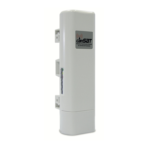
CDS-LiftIP
System for transmission of vi eo an au io from IP cameras in the elevators.
Key features of the module CDS-LiftIP:
•easy configuration on the switches, without the nee to connect a computer
•CDS-LiftIP can work both as a receiver an transmitter
•It ensures continuous an stable transmission capacity
•works in transparent mo e - it transmits all ata transparently, regar less of IP
cameras an recor ers.
•It works on both the Point-to-Point an Point-to-Multipoint receiving the signal
from 4 transmitters on two elevators.
•output power of 23 Bm at 5GHz ban operation
•built-in ual antenna MIMO 2 x 5 GHz 14 Bi (range 500m LoS)
•outer casing IP55
•operating temperature from -20 ° C to +55 ° C
Contents of the packa e
•CDS-LiftIP x 1 pc.
•PoE power supply 48V 0.5A with cable European 230V x 1pc.
•Mounting U-bolts x 1 pc.
•Users Manual an Declaration of conformity
DESCRIPTION OF CONNECTORS AND LED INDICATORS

DESCRIPTION OF CONNECTORS AND LED INDICATORS
RESET - reset button for the radio module to the default settings
PORT 2 - LAN port for connecting a second IP camera
PORT 1 - LAN port for connection to the DVR or connect the power adapter PoE48V
This port can also be used to connect a second IP camera through the LAN in the
power supply
SETTINGS – switches used to configure the device
LINK – LED indicator of the connection:
red - the signal is too strong (overdrive), or device is starting;
oran e - a link with a high signal level (very good signal);
reen - a valid link with the correct signal level;
off - the device is out of range or is incorrectly configured More information about the
level of radio signals can be obtained by logging on to the users’ panel website
POWER – red LED for power status
Preparation for operation
It is recommen e that the first start-up an configura-
tion of the system is ma e on the esk at small is-
tances. This can save a lot of valuable time with the
configuration of many ifferent cameras on the ob-
ject.
Function SETTINGS
Operating mode: Receiver
Transmitter
Operating channel
and IP address of the
device:
CH 36 (CE FCC)
CH 40 (CE FCC)
CH 44 (CE FCC)
CH 48 (CE FCC)
5.180 Ghz (192.168.112.x)
5.200 Ghz (192.168.113.x)
5.220 Ghz (192.168.114.x)
5.240 Ghz (192.168.115.x)
CH 149 (FCC)
CH 153 (FCC)
CH 157 (FCC)
5.745 Ghz (192.168.116.x)
5.765 Ghz (192.168.117.x)
5.785 Ghz (192.168.118.x)
In parentheses you can see the IP address of the device that depends on the settings. The
receiver always has the address of the ID 192.168.x.1. These addresses are reserved for radio
e uipment.

Function SETTINGS
CH 161 (FCC)
CH 165 (FCC)
5.805 Ghz (192.168.119.x)
5.825 Ghz (192.168.120.x)
Transmitter ID
number: Transmitter no 1 (192.168.x.2)
Transmitter no 2 (192.168.x.3)
Transmitter no 3 (192.168.x.4)
Transmitter no 4 (192.168.x.5)
MASTER receiver an all SLAVE transmitters must be set to the same operating channel to
establish connection. An then, each of the next set working nearby must be set to a ifferent
operating channel.
Multipoint Confi uration
CDS-LiftIP can be connecte in a point-to-multipoint configuration. You can connect the
evice from several elevators to one receiver. For such an application you shoul provi e
optical visibility between each transmitter an the receiver!
These settings are configure by switches 7 an 8 in each transmitter accor ing to the
following formula:
After 90 secon s since power on, unit will establish interconnection of sen ing ata
transparently between all ports of evices.
In the case of connection problems check:
•Directivity of antennas an if there are no obstacles between them
•Change the channel number to another one.
•Check the power supply capacity or replace another.


Assembly
Place mounting brackets esigne for mounting on a steel beam or rail in the appropriate
holes in the rear of the evice an tighten securely. Attach the evice to the construction with
the antenna pointe irectly at the point of receiving.
We use the U-Bolt han le which is inclu e .
WARNING
The antenna of the transmitter must "see” optically with an antenna at receiving
part of the set in the same polarity. Do not install the equipment rotate 90
egrees relative to each other as this will result in incompatibility of polarize
antennas.
Do not install the evices at istances of less than 0.5 m from each other. It is
recommen e to use a minimum istance of 1m.
Install receiver an antenna irecte exactly to the transmitting point. Set the esire
operating channel accor ing to the table. Channel numbers an polarity of antennas shoul
be the same in both cooperating transceivers. Connect the power cables together with power.
The evice must be powere from the supplie AC a apter PoE48V.
For installation you can use our accessories:
A) MTS-1D – Wall/roof mounting
B) MT-2D - Mounting to the pipe

Connection and start-up
It is recommen e that the first start-up an configuration of the system is ma e on the
esk at small istances. This can save a lot of valuable time with the configuration of
many ifferent cameras.
Transmitter (IP camera side):
•Set ipswitch 1 to OFF mo e (transmitter), set the operating channel accor ing to
the table, set the number of transmitter (if there is more than one transmitter).
•connect IP camera with a network cable with RJ45 PORT-2
•connect inclu e power supply PoE48V to PORT-1
•connect the secon camera by the network cable to the RJ45 LAN input in the
power supply of the transmitter.

The receiver (NVR side)
The receiver can be powered from a PoE injector or NVR PoE switch or PoE network.
•Set ipswitch No. 1 to ON mo e (receiver), set the operating channel by a table
i entical to the transmitter, set DIP7 an DIP8 ON (up)
•Connect NVR by the network cable to the PORT 1 or LAN port PoE in power supply.
•Connect power source for example inclu e PoE48V to PORT 2. To this port you
can also connect NVR with PoE or PoE network switch.

Application examples


Table of available operatin frequencies Table of frequencies outside the EU and the US
and paid
Use of specific channels accor ing to their
purpose:
•CE - Europe
•FCC - US
Using other frequencies depends on the legal regu-
lations of the country where you are. If you are not
sure about regulations in your country, consult your
supplier.
WARNING
The evice can operate at a frequency range an power that can be charge or
completely prohibite in your area or your country.

General warranty terms
Camsat grants a 24 month warranty for the CDS-LiftIP transmission kit
1. If the evice is not be operating properly, make sure, before returning the evice for
servicing, that everything was one accor ing to the operating manual
2. If the faulty evice is returne or sen in for repairs, a thorough written escription
of the signs of the evice’s faulty operation, inclu ing the operating environment an
the manner in which they appear, shoul be enclose
3. The prerequisite for exercising the warranty rights is enclosing the proof of purchase,
inclu ing the purchase ate an escription of amage, with the faulty evice
4. Warranty repairs cover only faults occurring ue to reasons inherent to the sol
evice.
5. Warranty repairs will be carrie out in the shortest possible amount of time not
excee ing 14 ays, counting from the moment of accepting the evice for servicing If parts
nee to be importe , the repair ea line may be exten e After the repairs have been carrie
out, the warranty perio will be exten e by the repair time.
7. The warrantor may refuse to carry out warranty repairs or terminate the warranty if
it is etermine that the seals place on evices or components comprising it are amage .
The warranty does not cover
1. Mechanical amage of evices an failures occurring ue to fortuitous events, such as:
fire, power gri overvoltage, electrical ischarges, power supply, effects of chemical
substances.
2. Damage occurring ue to: improper han ling of the evice, using the evice against its
inten e use or the operating manual, customer’s negligence, improper use
(temperature, humi ity, floo ing, ust, san ing up, improper power supply voltage)
3. Claims on account of the technical parameters, if they are consistent with those
in icate by the manufacturer
4. Marks create uring usage, such as scratches, soiling an localise wear are not
covere by warranty.
In cases not regulate by the terms of this warranty sheet, the appropriate provisions of the
Civil Co e are applicable.


Hereby, CAMSAT Gralak Przemyslaw eclares that the pro uct series CDS-LiftP meets the
essential requirements an other relevant provisions of Directive 1999/5 / WE.
The evice is CE marke , which in icates compliance with the gui elines of the Directive.
The evice can be sol an use for transmission in the 5 GHz ban . The frequency
range can be a juste using the settings in accor ance with legal regulations in every
country. It is your responsibility to be a equate settings of the complying with the
applicable laws in the country or region.
Device isposal
The mark presente to the left informs that this electrical or elec-
tronic evice, after its use has en e , cannot be thrown together
withhousehol refuse The evice shoul be elivere to a specia-
lise collection point Detaile information about the closest col-
lection pointis available from local authorities.
The proper isposal of this evice allows for preserving precious resources an avo-
i ingthe negative impact on health an environment, which may be en angere if
thewaste is han le improperly Improper waste isposal is subject to penalties pro-
vi e for in the appropriate regulations
Producer:
CAMSAT Gralak Przemysław
Ogro owa 2a
86-050 Solec Kujawski
Poland
Offer an information: www.camsat.com
Service: serwis@camsat.com.pl
Technical support Mon:
tel. + 48 505 272 224
Table of contents
Other Camsat Transmitter manuals

Camsat
Camsat TCO 5807m User manual

Camsat
Camsat TCO-7h Plus User manual

Camsat
Camsat CAM-9 User manual

Camsat
Camsat CDS-6IPeco Operator's manual

Camsat
Camsat VueNet EasyLink User manual

Camsat
Camsat CDS-5IPmini Operator's manual

Camsat
Camsat CAM-Analog2.0 User manual

Camsat
Camsat CAM8h-Multi2/AHD User manual

Camsat
Camsat GlobalCAM-LTE User manual

Camsat
Camsat CDS-6IP SMA User manual