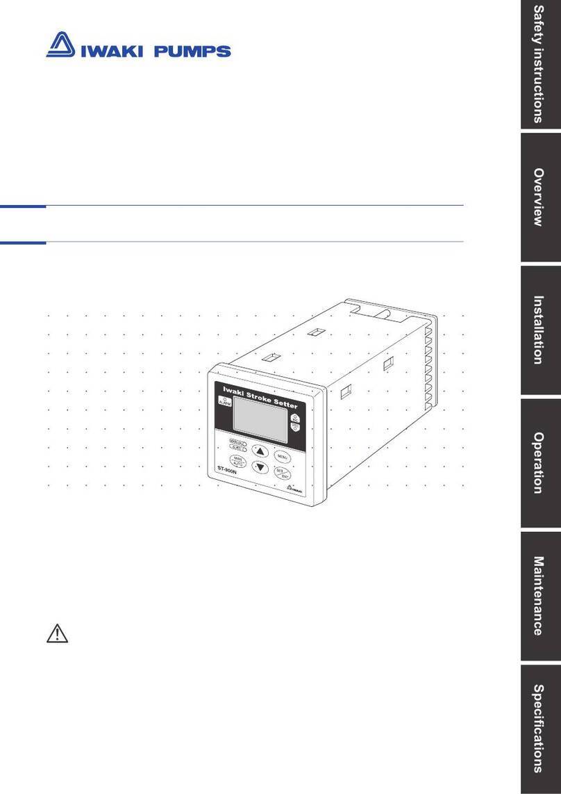
IWAKI PUMPS FDC-1 User manual

Read this manual before use of product
IWAKIController
ModelFDC-1
InstructionManual

Thank you for purchasing Iwaki Controller Model FDC-1.
This controller is an exclusive use for Iwaki pneumatic bellows pump. This document provides
“Notice and warnings”, “Overview”, “Set up”, “Operation” and “Maintenance”, and explains
handling and how to operate the controller.
To make sure for your safety and correct use, please read this manual entirely before using the
controller, and comprehend thoroughly for each clause.
Contents
NOTICE AND WARNING FOR HUMAN SAFETY ························ 1
OVERVIEW ··················································································· 3
1. Unpacking and inspection ····················································· 4
2. Specification ·········································································· 4
3. External dimensions ······························································ 5
4. Names and explanations of component devices ··················· 6
5. Explanation of work ······························································· 7
6. Main functions ······································································· 8
SETUP ··························································································· 9
1. Installation ·········································································· 10
2. Connection ·········································································· 10
Operation ···················································································· 17
1. How to operate ···································································· 18
2. How to set controller ···························································· 18
3. Operation screen ································································· 21
4. Setting confirming and setting change procedure ··············· 22
5. Pump operation ··································································· 22
6. Alarm reset procedure ························································· 23
Maintenance ··············································································· 24
1. Troubleshooting ··································································· 25
Please keep this document at customer’s site in order to review
whenever it is necessary. For additional information, please inquire
our local representatives in your area, or call us directly.

−1−
Important Instruction
Types of Symbols
Indicates that “Warning” or “Caution” must be exercised. Inside this
triangle, a concrete and practical image provided as a warning or cau-
tion message is depicted.
Indicates a prohibited action or procedure. Inside or near this circle, a
concrete and practical image of the activity to be avoided is depicted.
Indicates an important action or procedure which must be performed
or carried out without fail. Failure to follow the instructions herein
can lead to malfunction or damage to the pump.
Nonobservance or misapplication of the
contents of the “Caution” section could lead to
serious physical injury to the user or serious
damage to the product.
Warning Nonobservance or misapplication of the
contents of the “Warning” section could lead to
a serious accident, including death or injury.
Caution
For the Safe and Correct Handling of the Pump
•Read the "Safety Instructions" sections carefully to prevent accidents involving your customers
or other personnel and to avoid damage or loss of other assets. Always follow the instructions
and advice found in these sections.
•Observe and abide by the instructions described in this manual. These instructions are very
important for protecting pump users from potentially dangerous conditions and situations related
with the use of the pump system.
•The symbols relate to the following meanings described below:

Safety Section
WARNING
•For specified application only
Model FDC-1 is the exclusive use controller designed for IWAKI pneumatic drive bel-
lows pump FA, FF, FH, FW and FS Series. Do not use this controller for other pumps
or application.
•Do not disassemble and remodel
Do not disassemble and remodel the controller.
CAUTION
•Qualified operator only
The controller must be operated or maintained by the person who has enough knowl-
edge of the product and experience of handling of product.
•Place to be installed and stored
This controller is not explosion-proof design. Do not install or store the controller at
flammable atmosphere. Do not install or store the controller at corrosive
atmosphere.Otherwise, it may be failed or cause accident.
•Precautions for wiring proximity switches
Wrongly wired proximity switches (Right and Left) may cause the seizure of contacts.
Pay attention to the wiring.
•Specified voltage only
Do not use the controller with other voltage than specified one. Otherwise it may
causes fire or electrical shock.
- 2 -
Caution
No Remodeling
Prohibited
Prohibited
Prohibited
Prohibited

−3−
OVERVIEW
1. Unpacking and inspection.................... 4
2. Specification......................................... 4
3. External dimensions............................. 5
4. Names and explanations
of component devices......... 6
5. Explanation of work.............................. 7
6. Main functions...................................... 8

−4−
1) Please inspect immediately on the followings as soon as you receive the product, and inquire the shop you ordered if
any objectionable was found.
(1) Identify if the model number described on the front panel is the same as you ordered.
(2) Check if there is any damage(s) suffered from accident(s) during transportation.
(3) Confirm all of accessories were included. (if specified)
*Standard accessories: one each connector (CN1~CN6), total 6 connectors and a set of contact for the connectors.
*Optional accessories: Cable exclusively used for Electro- pneumatic regulator. (Only if ordered as an optional)
General
Spec.
Power supply DC24V + / - 10%
Power Consumption 24VA or less
Ambient temp. 0 ~ 50 °C
Ambient humidity 85% or less (No condensing)
Input
Spec. Leak sensor input Voltage between electrodes DC24V + / - 10%
Operating resistance Detect:0~15kohm (25k ohm or more: no detection)
Proximity switch input Input signal Proximity Switch (negative logic operation)
ON voltage level 3V or less
OFF voltage level 5V or more
External start input Input signal Potential free contact or NPN open collector output
ON voltage level 3V or less
OFF voltage level 18V or more
External alarm reset
input
Input signal Potential free contact or NPN open collector output
ON voltage level 3V or less
OFF voltage level 18V or more
Output
Spec. Solenoid valve
operation output
Output NPN open collector output
Output load voltage DC 24V + / - 10%
Output load current 1A (MAX)
Leak alarm output
Time-up alarm output
Life alarm output
Fast alarm output
Output NPN open collector output
Output load voltage DC 24V + / - 10%
Output load current 1A (MAX)
Electro-pneumatic
Regulator control output
Output signal Analog signal
Voltage range 0 ~ 10V
Resolution 8bit D/A converter
1. Unpacking and inspection
2. Specification

−5−
Fig. 1
PUMP CONTROLLER MODEL FDC-1
IWAKI
RUN
LEAK
TIME
LIFE
FAST CN1 CN2 CN3 CN4 CN5 CN6
141
+1
0
148
±
0.3
4-
φ
4.5
4-
φ
4.5
44+1
0
38±0.3
136
152
158
SELECT
MENU
ENT
AUTO MANU
148
38
48
42.3
(2)
Fig. 2
50
3
−
PT 1
/
4
PT 1
/
4
,
EXH.
52
(9)
72
22.5
×
×
OUT
SUP
PUSH OPEN
Zero span adjusting window
M12.4 pin, connector plug
(1) Controller (Fig. 1)
(2) Electro-pneumatic regulator (Option) (Fig. 2)
3. External dimensions

−6−
Fig. 3
;;;
;;;;;
;;;;;;;
;;;;;;
;;;;
;;
PUMP CONTROLLER MODEL FDC-1
IWAKI
;;;;;;
;;;;;;;;
;;;;;;;;;;
;;;;;;;;;;;;
;;;;;;;;;;;;;;
;;;;;;;;;;;;;;;;
;;;;;;;;;;;;;;;;;;
;;;;;;;;;;;;;;;;;;;;
;;;;;;;;;;;;;;;;;;;;;;
;;;;;;;;;;;;;;;;;;;;;;;;
;;;;;;;;;;;;;;;;;;;;;;;;;;
;;;;;;;;;;;;;;;;;;;;;;;;;;;;
;;;;;;;;;;;;;;;;;;;;;;;;;;;;;;
;;;;;;;;;;;;;;;;;;;;;;;;;;;;;;;;
;;;;;;;;;;;;;;;;;;;;;;;;;;;;;;;;;;
;;;;;;;;;;;;;;;;;;;;;;;;;;;;;;;;;;;;
;;;;;;;;;;;;;;;;;;;;;;;;;;;;;;;;;;;;;;
;;;;;;;;;;;;;;;;;;;;;;;;;;;;;;;;;;;;;;;;
;;;;;;;;;;;;;;;;;;;;;;;;;;;;;;;;;;;;;;;;;;
;;;;;;;;;;;;;;;;;;;;;;;;;;;;;;;;;;;;;;;;;;;;
;;;;;;;;;;;;;;;;;;;;;;;;;;;;;;;;;;;;;;;;;;;;;;
;;;;;;;;;;;;;;;;;;;;;;;;;;;;;;;;;;;;;;;;;;;;;;;;
;;;;;;;;;;;;;;;;;;;;;;;;;;;;;;;;;;;;;;;;;;;;;;;;;;
;;;;;;;;;;;;;;;;;;;;;;;;;;;;;;;;;;;;;;;;;;;;;;;;;;;;
;;;;;;;;;;;;;;;;;;;;;;;;;;;;;;;;;;;;;;;;;;;;;;;;;;;;;;
;;;;;;;;;;;;;;;;;;;;;;;;;;;;;;;;;;;;;;;;;;;;;;;;;;;;;;;;
;;;;;;;;;;;;;;;;;;;;;;;;;;;;;;;;;;;;;;;;;;;;;;;;;;;;;;;;;;
;;;;;;;;;;;;;;;;;;;;;;;;;;;;;;;;;;;;;;;;;;;;;;;;;;;;;;;;;;;;
;;;;;;;;;;;;;;;;;;;;;;;;;;;;;;;;;;;;;;;;;;;;;;;;;;;;;;;;;;;;;;
;;;;;;;;;;;;;;;;;;;;;;;;;;;;;;;;;;;;;;;;;;;;;;;;;;;;;;;;;;;;;;;;
;;;;;;;;;;;;;;;;;;;;;;;;;;;;;;;;;;;;;;;;;;;;;;;;;;;;;;;;;;;;;;;;;;
;;;;;;;;;;;;;;;;;;;;;;;;;;;;;;;;;;;;;;;;;;;;;;;;;;;;;;;;;;;;;;;;;;;;
;;;;;;;;;;;;;;;;;;;;;;;;;;;;;;;;;;;;;;;;;;;;;;;;;;;;;;;;;;;;;;;;;;;;;;
;;;;;;;;;;;;;;;;;;;;;;;;;;;;;;;;;;;;;;;;;;;;;;;;;;;;;;;;;;;;;;;;;;;;;;;;
;;;;;;;;;;;;;;;;;;;;;;;;;;;;;;;;;;;;;;;;;;;;;;;;;;;;;;;;;;;;;;;;;;;;;;;;;;
;;;;;;;;;;;;;;;;;;;;;;;;;;;;;;;;;;;;;;;;;;;;;;;;;;;;;;;;;;;;;;;;;;;;;;;;;;;;
;;;;;;;;;;;;;;;;;;;;;;;;;;;;;;;;;;;;;;;;;;;;;;;;;;;;;;;;;;;;;;;;;;;;;;;;;;;;;;
;;;;;;;;;;;;;;;;;;;;;;;;;;;;;;;;;;;;;;;;;;;;;;;;;;;;;;;;;;;;;;;;;;;;;;;;;;;;;;;;
;;;;;;;;;;;;;;;;;;;;;;;;;;;;;;;;;;;;;;;;;;;;;;;;;;;;;;;;;;;;;;;;;;;;;;;;;;;;;;;;;;
;;;;;;;;;;;;;;;;;;;;;;;;;;;;;;;;;;;;;;;;;;;;;;;;;;;;;;;;;;;;;;;;;;;;;;;;;;;;;;;;;;;;
;;;;;;;;;;;;;;;;;;;;;;;;;;;;;;;;;;;;;;;;;;;;;;;;;;;;;;;;;;;;;;;;;;;;;;;;;;;;;;;;;;;;;
;;;;;;;;;;;;;;;;;;;;;;;;;;;;;;;;;;;;;;;;;;;;;;;;;;;;;;;;;;;;;;;;;;;;;;;;;;;;;;;;;;;;;
;;;;;;;;;;;;;;;;;;;;;;;;;;;;;;;;;;;;;;;;;;;;;;;;;;;;;;;;;;;;;;;;;;;;;;;;;;;;;;;;;;;;;
;;;;;;;;;;;;;;;;;;;;;;;;;;;;;;;;;;;;;;;;;;;;;;;;;;;;;;;;;;;;;;;;;;;;;;;;;;;;;;;;;;;;;
;;;;;;;;;;;;;;;;;;;;;;;;;;;;;;;;;;;;;;;;;;;;;;;;;;;;;;;;;;;;;;;;;;;;;;;;;;;;;;;;;;;;;
;;;;;;;;;;;;;;;;;;;;;;;;;;;;;;;;;;;;;;;;;;;;;;;;;;;;;;;;;;;;;;;;;;;;;;;;;;;;;;;;;;;;;
;;;;;;;;;;;;;;;;;;;;;;;;;;;;;;;;;;;;;;;;;;;;;;;;;;;;;;;;;;;;;;;;;;;;;;;;;;;;;;;;;;;;;
;;;;;;;;;;;;;;;;;;;;;;;;;;;;;;;;;;;;;;;;;;;;;;;;;;;;;;;;;;;;;;;;;;;;;;;;;;;;;;;;;;;;;
;;;;;;;;;;;;;;;;;;;;;;;;;;;;;;;;;;;;;;;;;;;;;;;;;;;;;;;;;;;;;;;;;;;;;;;;;;;;;;;;;;;;;
;;;;;;;;;;;;;;;;;;;;;;;;;;;;;;;;;;;;;;;;;;;;;;;;;;;;;;;;;;;;;;;;;;;;;;;;;;;;;;;;;;;;;
;;;;;;;;;;;;;;;;;;;;;;;;;;;;;;;;;;;;;;;;;;;;;;;;;;;;;;;;;;;;;;;;;;;;;;;;;;;;;;;;;;;;;
;;;;;;;;;;;;;;;;;;;;;;;;;;;;;;;;;;;;;;;;;;;;;;;;;;;;;;;;;;;;;;;;;;;;;;;;;;;;;;;;;;;;;
;;;;;;;;;;;;;;;;;;;;;;;;;;;;;;;;;;;;;;;;;;;;;;;;;;;;;;;;;;;;;;;;;;;;;;;;;;;;;;;;;;;;;
;;;;;;;;;;;;;;;;;;;;;;;;;;;;;;;;;;;;;;;;;;;;;;;;;;;;;;;;;;;;;;;;;;;;;;;;;;;;;;;;;;;;;
;;;;;;;;;;;;;;;;;;;;;;;;;;;;;;;;;;;;;;;;;;;;;;;;;;;;;;;;;;;;;;;;;;;;;;;;;;;;;;;;;;;;;
;;;;;;;;;;;;;;;;;;;;;;;;;;;;;;;;;;;;;;;;;;;;;;;;;;;;;;;;;;;;;;;;;;;;;;;;;;;;;;;;;;;;;
;;;;;;;;;;;;;;;;;;;;;;;;;;;;;;;;;;;;;;;;;;;;;;;;;;;;;;;;;;;;;;;;;;;;;;;;;;;;;;;;;;;;;
;;;;;;;;;;;;;;;;;;;;;;;;;;;;;;;;;;;;;;;;;;;;;;;;;;;;;;;;;;;;;;;;;;;;;;;;;;;;;;;;;;;;
;;;;;;;;;;;;;;;;;;;;;;;;;;;;;;;;;;;;;;;;;;;;;;;;;;;;;;;;;;;;;;;;;;;;;;;;;;;;;;;;;;;
;;;;;;;;;;;;;;;;;;;;;;;;;;;;;;;;;;;;;;;;;;;;;;;;;;;;;;;;;;;;;;;;;;;;;;;;;;;;;;;;;;
;;;;;;;;;;;;;;;;;;;;;;;;;;;;;;;;;;;;;;;;;;;;;;;;;;;;;;;;;;;;;;;;;;;;;;;;;;;;;;;;;
;;;;;;;;;;;;;;;;;;;;;;;;;;;;;;;;;;;;;;;;;;;;;;;;;;;;;;;;;;;;;;;;;;;;;;;;;;;;;;;
;;;;;;;;;;;;;;;;;;;;;;;;;;;;;;;;;;;;;;;;;;;;;;;;;;;;;;;;;;;;;;;;;;;;;;;;;;;;;
;;;;;;;;;;;;;;;;;;;;;;;;;;;;;;;;;;;;;;;;;;;;;;;;;;;;;;;;;;;;;;;;;;;;;;;;;;;
;;;;;;;;;;;;;;;;;;;;;;;;;;;;;;;;;;;;;;;;;;;;;;;;;;;;;;;;;;;;;;;;;;;;;;;;;
;;;;;;;;;;;;;;;;;;;;;;;;;;;;;;;;;;;;;;;;;;;;;;;;;;;;;;;;;;;;;;;;;;;;;;;
;;;;;;;;;;;;;;;;;;;;;;;;;;;;;;;;;;;;;;;;;;;;;;;;;;;;;;;;;;;;;;;;;;;;;
;;;;;;;;;;;;;;;;;;;;;;;;;;;;;;;;;;;;;;;;;;;;;;;;;;;;;;;;;;;;;;;;;;;
;;;;;;;;;;;;;;;;;;;;;;;;;;;;;;;;;;;;;;;;;;;;;;;;;;;;;;;;;;;;;;;;;
;;;;;;;;;;;;;;;;;;;;;;;;;;;;;;;;;;;;;;;;;;;;;;;;;;;;;;;;;;;;;;;
;;;;;;;;;;;;;;;;;;;;;;;;;;;;;;;;;;;;;;;;;;;;;;;;;;;;;;;;;;;;;
;;;;;;;;;;;;;;;;;;;;;;;;;;;;;;;;;;;;;;;;;;;;;;;;;;;;;;;;;;;
;;;;;;;;;;;;;;;;;;;;;;;;;;;;;;;;;;;;;;;;;;;;;;;;;;;;;;;;;
;;;;;;;;;;;;;;;;;;;;;;;;;;;;;;;;;;;;;;;;;;;;;;;;;;;;;;;
;;;;;;;;;;;;;;;;;;;;;;;;;;;;;;;;;;;;;;;;;;;;;;;;;;;;;
;;;;;;;;;;;;;;;;;;;;;;;;;;;;;;;;;;;;;;;;;;;;;;;;;;;
;;;;;;;;;;;;;;;;;;;;;;;;;;;;;;;;;;;;;;;;;;;;;;;;;
;;;;;;;;;;;;;;;;;;;;;;;;;;;;;;;;;;;;;;;;;;;;;;;
;;;;;;;;;;;;;;;;;;;;;;;;;;;;;;;;;;;;;;;;;;;;;
;;;;;;;;;;;;;;;;;;;;;;;;;;;;;;;;;;;;;;;;;;;
;;;;;;;;;;;;;;;;;;;;;;;;;;;;;;;;;;;;;;;;;
;;;;;;;;;;;;;;;;;;;;;;;;;;;;;;;;;;;;;;;
;;;;;;;;;;;;;;;;;;;;;;;;;;;;;;;;;;;;;
;;;;;;;;;;;;;;;;;;;;;;;;;;;;;;;;;;;
;;;;;;;;;;;;;;;;;;;;;;;;;;;;;;;;;
;;;;;;;;;;;;;;;;;;;;;;;;;;;;;;;
;;;;;;;;;;;;;;;;;;;;;;;;;;;;;
;;;;;;;;;;;;;;;;;;;;;;;;;;;
;;;;;;;;;;;;;;;;;;;;;;;;;
;;;;;;;;;;;;;;;;;;;;;;;
;;;;;;;;;;;;;;;;;;;;;
;;;;;;;;;;;;;;;;;;;
;;;;;;;;;;;;;;;;;
;;;;;;;;;;;;;;;
;;;;;;;;;;;;;
;;;;;;;;;;;
;;;;;;;;;
;;;;;;;
;;;;;
;;;
RUN
LEAK
TIME
LIFE
FAST CN1 CN2 CN3 CN4 CN5 CN6
SELECT
MENU
ENT
AUTO MANU
①
②
⑦
⑥
④③
⑤
⑨⑩⑧ ⑪
①LCD panel:
Describes setting item, operating condition and contents of alarm for each pump in English abbreviation. (2 lines, 16
alphabets)
②key, key and key :
key: To be used for writing selection of each setting value. At that time, ENTER key will be used for
confirmation of figure down of value and operation.
By the combination of MENU key and SELECT key, it is able to access to each setting screen individually.
key: The designation of setting screens No., changeover of Stop & Run and Alarm reset can be executed.
③Controller operation mode selection key (MANU operation):
When LED turns on by depressing key, operation mode can be switched to manual operation mode.
Manual mode can effect all sort of setting and work on the panel manually.
④Controller operation mode selection key (AUTO operation):
When LED turns on by depressing key, operation mode can be switched to automatic operation mode.
Automatic operation mode can effect all sort of setting on the panel manually, and remote operation can be effected
for pump start, pump stop and alarm reset respectively by zero voltage contact signal or open collector signal.
⑤LEDs:
There are 5 LEDs in total. The explanation of each LED is as follows.
RUN: Turns on while pump is operating. (Green)
LEAK: Turns on when leak alarm is detected. (Red)
TIME: Turns on when time-up alarm is detected. (Red)
LIFE: Turns on when life alarm is detected. (Red)
FAST: Turns on when fast alarm is detected. (Red)
⑥Exclusive connector for alarm output signal (CN1):
At the same time of each alarm detection, each alarm output signal are made out to the external. Connect this
controller and your equipment with an output cable (optional).
⑦Connector exclusively used for driving solenoid valve (CN2):
Solenoid valve driven signal will be generated. Then, connect this controller and solenoid valve (single or double
solenoid valve) with an output cable (optional).
⑧Connector exclusively used for pump input (CN3) :
This connector effects to input the signal of proximity switch and leak sensor. Connect this controller and pump
with an input cable (optional).
⑨Connector exclusively used for external input (CN4):
This connector effects to input signals of pump start, pump stop and alarm reset respectively from the external.
Connect this controller and your equipment with an input cable (optional).
⑩Connector exclusively used for electro-pneumatic regulator (CN5):
This connector generates regulator control signal for flow rate control. Connect this controller and electro-
pneumatic regulator with an output cable (optional).
⑪Connector exclusively used for power supply (CN6):
This connector supplies DC24V + / - 10%.
Connect this controller and power supply with a cable for power supply (optional).
AUTO
MANU
ENTER
SELECT
ENTER
SELECT
MENU
4. Names and explanations of component devices

−7−
(1) Pump operation:
①When proximity switch R input is on, solenoid valve operation output keeps ON condition.
②Even if proximity switch R input is off, solenoid valve operation output keeps ON condition.
③At the condition of proximity switch L input is on, solenoid valve operation output becomes off.
④Then, until proximity switch R input comes on, solenoid valve operation output keeps off condition.
⑤The above operations (①~④) shall be repeated in order.
②
①
Proximity switch L
Proximity switch R
Solenoid valve
operation output L
Solenoid valve
operation output R
(2) Flow rate control:
1 shot flow rate for F pump has been arranged; discharge capacity shall be “pump stroke rate times 1 shot flow rate”.
When the flow rate was set arbitrarily, stroke rate shall be converted automatically within the controller. Comparing
this converted stroke rate and operating cycle of proximity switch, which is effected to input into controller while
pump is operating, control voltage (DC0~10V) to Electro-pneumatic regulator (ER1) shall be adjusted. Varying
secondary air pressure of electro-pneumatic regulator (ER1), discharge capacity shall be controlled.
(3) Leak alarm:
This function effects to stop pump with alarm signal when pump brings about leakage.
It detects leakage and makes output signal by that leaked liquid conducts between electrodes (C1- C2 or D1-D2) of
which set up corresponding to each bellows (left and right).
Receiving this alarm, the controller effects warning, and put control signal off to Electro-pneumatic regulator
simultaneously. Then, it makes stop pump.
On this occasion, pneumatic pressure to drive inside of pump shall be released and becomes no-pressure only when
Electro-pneumatic regulator (optional) is being used.
(4) Time up alarm:
This function effect to alarm when pump stops or stroke speed becomes abnormally slow down for some reason.
Output for solenoid valve still keeps operating condition, though. Time set for criterion of warning shall be
executed on setting screen No.8.
It makes output as an alarm in case of whatever longer stroke time (t1, t2 and t3), than preset time t0. When all of
t1, t2 and t3 become shorter than t0, this alarm shall be reset automatically, and starts operation again.
5. Explanation of work
t1t2t3
t0t0t0
Proximity switch L
Proximity switch R
Time up alarm

−8−
(5) Life alarm:
This function effects to alarm and notice when accumulated count number becomes beyond the fixed total count
number which was set manually.
Output for solenoid valve and Electro-pneumatic regulator (optional) still keep operating condition, though.
Total count number setting can be executed at setting screen No.9, and also, it is able to reset by manual reset or
reset signal from the externals. After input of reset, Life alarm detection is neglected for 2 minutes. After 2 minutes
past, it detects again if pump is operating condition.
(6) Fast alarm:
This function effects to alarm when pump stroke became abnormally faster than the preset stroke rate for some
reasons. Output for solenoid valve and Electro-pneumatic regulator (optional) still keep operating condition,
though.
Stroke rate setting for criterion of warning shall be executed on setting screen No.10.
If actual operating stroke becomes slower than the fixed stroke, then it resets automatically. Also it is able to reset
by reset signal from manual reset device. After reset signal input, it neglects detection for 2 minutes. After
2minuites, it may start again if it is in alarm condition.
①Possible to fix a specified flow rate control against the load fluctuation at discharge side.
②Possible to set flow rate freely.
③Possible to display stroke rate, flow rate and total count number while pump is operating.
④In case of bellows broken, leak alarm will be output to the externals. Pump stops simultaneously with alarm output.
⑤Possible to set necessary time set for 1 shot of pump operation. When the time for 1 shot of pump is beyond the
setting time, time up alarm will be output to the externals.
⑥Possible to set total counts number of pump. When count number for 1 shot of pump is beyond the setting number,
life alarm will be output to the externals.
⑦Possible to set maximum counts stroke rate. When count number for stroke is beyond the setting number while its
operation, first alarm will be outputting to the externals.
⑧Possible to set alarm reset for start / stop of pump by signals from the externals.
⑨Possible to select operation mode of controller from MANU and AUTO.
⑩In case of proximity switch broken, possible to operate pump by timer mode until proximity switch is replaced.
6. Main functions

−9−
SETUP
1. Installation.......................................... 10
2. Connection......................................... 10

−10−
(1) Installation to instrument panels (see the illustration):
Fig. 4
• Cutout (W141 x H44mm) on instrument panel.
• Tap 4 screw holes (W148 x H38mm) for fitting.
• Insert the controller into the hole, and fix firmly with M4 screws.
• Install with enough room toward the depth.
PUMP CONTROLLER MODEL FDC-1
IWAKI
RUN
LEAK
TIME
LIFE
FAST CN1 CN2 CN3 CN4 CN5 CN6
141
+1
0
148
±
0.3
4-
φ
4.5
4-
φ
4.5
44+1
0
38±0.3
136
152
158
SELECT
MENU
ENT
AUTO MANU
148
38
48
42.3
(2)
1. Installation
WARNING
•Do not install or store at explosion atmosphere, such places causing particulate or corrosion
gases (such as chlorine gas).
It may cause fire or harm to human body.
2. Connection
Execute wiring and piping referring illustrations 5 & 6 of which shows electrical wiring of controller and piping
drawing of air and charts 2 ~ 7 as well as an instruction of pump.
Caution: In case of wrong wiring, it may cause breakdown or wrong operation of controller and
pump. Please pay special attention!

−11−
CN 1
GND
GND
GND
CN 3
CN 2
◯
− ◯
+
LR
FA・FF・FH・FW・FS pump
C1
C2D1
D2
SV ER
CN 4
GND
CN 5
CN 6
GND
FR
Leak alarm
DC+24V output
Time up alarm
DC+24V output
Life alarm
DC+24V output
DC+24V output
Fast alarm
SV output R
DC+24V output
DC+24V output
SV output L
Leak detection input
DC+24V output
Proximity switch input R
DC+24V output
Proximity switch input L
Red (Brown)
White (Black)
Black (Blue)
Red (Brown)
White (Black)
Black (Blue)
Proximity switch
input R
Proximity switch
input L
Electrode Electrode
Your device
External start input
External alarm reset input
Electro-pneumatic reguleter
DC+24V output
Electro-pneumatic reguleter
DC0-+10V output
Electro-pneumatic reguleter GND
DC+24V supply
GND supply
DC+24V
power source
SV: Electro-magnetic valve
(Single solenoid valve)
ER: Electro-pneumatic regulater
FR: Manual regulater
Note: L and R are in reverse for air piping of FS pump.
Fig. 5 Wiring for single solenoid valve.

−12−
CN 1
CN 3
CN 2
◯
− ◯
+
LR
C1
C2D1
D2
WSV ER
CN 4
CN 5
CN 6
FR
Leak alarm
DC+24V output
Time up alarm
DC+24V output
Life alarm
DC+24V output
DC+24V output
Fast alarm
SV output R
DC+24V output
DC+24V output
SV output L
GND
GND
GND
Leak detection input
DC+24V output
Proximity switch input R
DC+24V output
Proximity switch input L
Red
(Brown)
White
(Black)
Black
(Blue)
Red
(Brown)
White
(Black)
Black
(Blue)
FA・FF・FH・FW・FS pump
Proximity switch
input R
Proximity switch
input L
Electrode Electrode
GND
GND
External start input
External alarm reset input
Electro-pneumatic reguleter
DC+24V output
Electro-pneumatic reguleter
DC0-+10V output
Electro-pneumatic reguleter GND
DC+24V supply
GND supply
DC+24V
power source
WSV: Electro-magnetic valve
(Double solenoid valve)
ER: Electro-pneumatic regulater
FR: Manual regulater
Note: L and R are in reverse for air piping of FS pump.
Fig. 6 Wiring for double-solenoid valve.
Your device

−13−
CN1 Chart 2
OUTPUT Purpose of wiring Wiring objects
Pin No. Marker Tube No.
1P 1 Leak alarm
Connection between FDC-1 and
your equipment
2P 2COM (DC+24V)
3P 3Time up alarm
4P 4COM (DC+24V)
5P 5Life alarm
6P 6COM (DC+24V)
7P 7 Fast alarm
8P 8COM (DC+24V)
OUTPUT Purpose of wiring
Pin No. Marker Tube No.
1P 9 Solenoid valve output R-
2P 10 Solenoid valve output R+
3P 11 Solenoid valve output L-
4P 12 Solenoid valve output L+
Connection between FDC-1 and
Solenoid valve (Note)
Wiring objects
Note: In case of connection with single solenoid, it is no matter to connect pin Nos. 3P and 4P
1P
2P
3P
4P
5P
6P
7P
8P
FDC-1 Controller inside
DC+24V
Fig. 7 Output scheme
Your equipment side
Inside circuit
CN2 Chart 3

−14−
INPUT Purpose of wiring
Pin No. Marker Tube No.
1P 21 External input (pump start, stop)
2P 22 GND
3P 23 External input (alarm reset)
4P 24 GND
Connection between FDC-1 and
your equipment
Wiring objects
(Brown) (Black) (Blue) : FH, FA type pump proximity switch
(Red) (White) (Black) : FF, FW, FS type pump proximity switch
Note: Proximity switch L & R signify Left and Right respectively from the view of pump inlet port.
For FH-40R, FA-40VE, L & R are Upper side and Lower side respectively.
INPUT Purpose of wiring Wiring objects
Pin No. Marker Tube No.
1P 13 Leak sensor C1, D1
Connection between FDC-1 and
pump
2P 14 Leak sensor C2, D2
3P 15 Proximity switch R (Brown) [Red]
4P 16 Proximity switch R (Black) [White]
5P 17 Proximity switch R (Blue) [Black]
6P 18 Proximity switch L (Brown) [Red]
7P 19 Proximity switch L (Black) [White]
8P 20 Proximity switch L (Blue) [Black]
CN3 Chart 4
CN4 Chart 5
1P
2P
3P
4P
DC+24V
NPN Open collector
Your equipment side
Start signal
Alarm reset signal or
or
Potential free
contact
Inside of FDC-1
Same as above
Fig. 8 CN4 Input scheme
Inside
circuit

−15−
INPUT Purpose of wiring
Pin No. Marker Tube No.
1P 25 Power supply for Electro-pneumatic regulator (Red)
2P 26 Input signal for Electro-pneumatic regulator (White)
3P 27 GND for Electro-pneumatic regulator (Black)
Connection between FDC-1 and
Electro-pneumatic regulator
Wiring objects
INPUT Purpose of wiring
Pin No. Marker Tube No.
1P 28 DC24V Power supply +
2P 29 GND
Connection between FDC-1 and
power supply (Note)
Wiring objects
Note: Please provides DC24V power supply with 1A or more.
CN5 Chart 6
Note: Wiring is not needed when electro-pneumatic regulator is not used.
CN6 Chart 7
Chart 8 Table of wiring devices
FDC-1 side
connector Contact Wire Remarks
Cross section mm2AWG
CN1 VHR-8N BVH-21T-P1.1 0.5 20 8 wires, 5m or less
CN2 VHR-4N BVH-21T-P1.1 0.5 20 4 wires, 5m or less
CN3 XHP-8 BXH-001T-P0.6 0.3 22 8 wires, 5m or less
CN4 XHP-4 BXH-001T-P0.6 0.3 22 4 wires, 5m or less
CN5 XHP-3 BXH-001T-P0.6 0.3mm2, Outer dia. φ5.9 4 wires shield cord、5m or less
CN6 VHR-2N BVH-21T-P1.1 0.5 20 2 wires, 5m or less
Note 1: Use the connector and pin made by J.S.T. Mfg. Co., Ltd.
2: For the wiring of CN5, use Omron made XS2C-D422 as electro-pneumatic regulator side I/O connector. Refer
to Chart 9) for connection.
Chart 9 Wiring of electro-pneumatic regulator
FDC-1 side
connector Electro-pneumatic regulator
side I/O connector
1P 1P
2P 4P
3P 3P
Note: Connect shield cord to 3P of FDC-1 side connector XHP-3.

−16−
Caution
• Proximity switch cord of FF, FW and FS pumps consists of three wires of black, white and red. Wrong connection
of them will cause the failure of proximity switch.
Caution
1. Standard proximity switch can not be used to handle flammable liquid such as solvent or so. Ask IWAKI for
explosion-proof proximity switch.
2. Electrode can not be used to handle flammable liquid. If used, it may spark resulting in fire.
Caution
• Use power source of DC24V plus minus 10% range.
■Air piping
Figure 5 and 6 show electrical wiring and air piping schemes. Make the air piping according to following procedures
referring to the schemes.
(1) Precautions for air piping
a) Bad quality air will give bad influence to the performance and life of the equipments.
Supply clean air which contains no solid matters, water and oil.
b) Flush pipes before they are connected. When the seal tape is used for piping, pay attention so that the tape can be
get into the pipe.
c) Install a regulator before the electro-pneumatic regulator (option) and adjust supplied air pressure to get the stable
performance.
d) If the electro-pneumatic regulator is not used, connect pipe from manual regulator
(FR) on Fig. 5 and 6 to the solenoid valve.
Note: The secondary side set pressure of manual regulator must not exceed the max. supply air pressure of the pump.
Refer to the instruction manual of the used pump.
(Pay attention to the pumped liquid temperature range.)
(2) Piping of electro-pneumatic regulator
Install the electro-pneumatic regulator between the manual regulator and the solenoid valve. Refer to the
instruction manual of the electro-pneumatic regulator for details.
The first side set pressure of electro-pneumatic regulator : Between the max. supply air pressure of pump and the
max. supply air pressure of pump + 0.05 MPa (Pay attention to the pumped liquid temperature range.)

−17−
OPERATION
1. How to operate................................... 18
2. How to set controller.......................... 18
3. Operation screen ............................... 21
4. Setting confirmation and
setting change procedure ........... 22
5. Pump operation.................................. 22
6. Alarm reset procedure ....................... 23

−18−
1. How to operate
①Confirm if pump, solenoid valve, alarm devices and electro-pneumatic regulator are connected correctly each other,
and if it is connected DC24V as well.
(Adjust voltage to DC24V with the help of transformer if it is an abnormal voltage.)
②Supply air to preliminary inlet of electro-pneumatic regulator with manual regulator.
2-1 Flow of setting
Flow of setting is as follow.
Setting Pump Sensor
Power on
No.1
No.2
No.3
No.4
No.5
No. 6
No. 7
No. 8
No. 9
No. 10
No. 11
Selecting Timer
NO
Selecting Sensor
YES
No. 3
No. 8
No. 9
No. 10
No. 11
No.2 NO
No.12
No.3
No.9
No.11
No.3
No.9
No.11
No.12
YES
Setting Electro-pneumatic
regulator presence
Setting 1 shot of pump
discharge
Setting necessary pump
discharge
Setting maximum air supply
pressure for Electro-pneumatic
regulator
Completion of setting
(Control of constant discharge)
Setting key protect for setting
operation
Setting standard No. of stroke
of detection
Setting standard No. of count
of detection for Life alarm
Setting standard time of
detection for Time up alarm
Setting air supply pressure
when pump starts
Setting minimum air supply
pressure for Electro-pneumatic
regulator
Setting 1 shot of pump
discharge
Setting standard time of
detection for Time up alarm
Setting standard count number
of detection for Life alarm
Setting standard stroke rate of
detection for First alarm
Setting key protect for setting
operation
Completion of setting
(Normal operation)
Setting Electro-pneumatic
regulator presence
No.5
No. 6
No. 7
Setting maximum air supply
pressure for Electro-pneumatic
regulator
Setting air supply pressure
when pump starts
Setting minimum air supply
pressure for Electro-pneumatic
regulator
Setting Pump stroke rate
Setting 1 shot of pump
discharge
Setting standard count number
of detection for Life alarm
Setting key protect for setting
operation
Completion of setting
(Timer mode)
Setting Pump stroke rate
Setting 1 shot of pump
discharge
Setting standard count number
of detection for Life alarm
Setting key protect for setting
operation
Completion of setting
(Timer mode)
2. How to set controller
Table of contents
Other IWAKI PUMPS Controllers manuals
Popular Controllers manuals by other brands

Mitsubishi Electric
Mitsubishi Electric MELSEC iQ-R Series user manual

Geovent
Geovent PowerSmart II user manual

ARAG
ARAG 4669 Series General instruction for installation use and maintenance

oventrop
oventrop Hydromat DTR Installation and operating instructions

SOMFY
SOMFY HOME MOTION Smoove RS100 io instructions

Peerless Pump
Peerless Pump Sealtrode P Series instructions