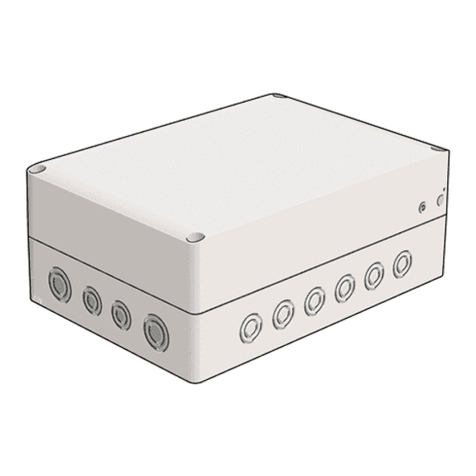
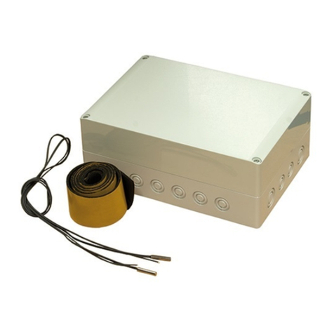
Nibe AXC 40 User guide

Installer manual
LEK
AXC 40
Accessories
IHB GB 0935-1
031444


Table of Contents
1 General 2
Contents 2
Component positions 2
2 Common electrical connection 3
Connecting the supply 3
Connecting communication 3
3 Mixing valve controlled additional
heat (oil/gas boiler/district heat-
ing) 4
General 4
Pipe connections 4
Outline diagram 5
Electrical connection 7
Program settings 8
Electrical circuit diagram 9
4 Hot water circulation 10
General 10
Outline diagram 10
Electrical connection 12
Program settings 12
Electrical circuit diagram 13
5 Groundwater pump 14
General 14
Outline diagram 14
Electrical connection 16
Program settings 16
Electrical circuit diagram 17
1Table of Contents |AXC 40

This accessory is used to enable connection and control
of:
႑Mixing valve controlled additional heat
႑Pump for hot water circulation
႑Groundwater pump
Contents
Cable ties4x
Heating pipe paste2x
Insulation tape1x
Kit for accessory card1x
Aluminium tape2x
Temperature sensor2x
Component positions
LEK
AA5-X4
AA5-S2
AA5-X2
AA5-X9
X1
FA1
AA5-F1
AA5
Miniature circuit-breakerFA1
Terminal block, power supplyX1
Accessory cardAA5
Terminal block, sensors and external blockingAA5-X2
Terminal block, communicationAA5-X4
Terminal block, circulation pump, mixing valve and auxiliary relayAA5-X9
DIP switchAA5-S2
Fine-wire fuseAA5-F1
AXC 40Chapter 1 | General2
1 General

NOTE
All electrical connections must be carried out by
an authorised electrician.
Electrical installation and wiring must be carried
out in accordance with the stipulations in force.
F1145/F1245 must not be powered when in-
stalling AXC 40.
Electrical circuit diagrams are at the end of the chapter
for each connection option.
Connecting the supply
Connect the power supply to terminal block X1 as illus-
trated.
3
2
1N
230V 50Hz-X1
L
PE
Connecting communication
The first accessory card must be connected directly to the
heat pump's terminal block AA3-X4. In the event of sev-
eral accessory cards the following cards must be connec-
ted in series with the previous card.
Use cable type LiYY, EKKX or similar.
1
2
3
4
5
6
7
8
AA5-X4
15
A
B
GND
A
B
GND
A
B
GND
A
B
GND
A
B
GND
14
13
AA3-X4
1
2
3
4
5
6
7
8
AA5-X4
F1245
AA3-X4
F1145
AA3-X4
Accessory card 1
Accessory card 2
ON
12345678
-X9
-X2
24 20212223 1516171819 1011121314 567891
1
N
L
PE
PE
1
2
3
4
5
6
7
8
2
3
4
5
6
7
8
9
234
-X8
-X4
-X10
-X1
AA5-X4
ON
12345678
-X9
-X2
24 20212223 1516171819 1011121314 567891
1
N
L
PE
PE
1
2
3
4
5
6
7
8
2
3
4
5
6
7
8
9
234
-X8
-X4
-X10
-X1
AA5-X4
F1145/F1245
3Chapter 2 | Common electrical connectionAXC 40
2 Common electrical connection

General
This connection enables an external additional heater,
e.g. an oil boiler, to aid with heating.
The heat pump controls a mixing valve and a circulation
pump via AXC 40. If the heat pump does not manage to
keep the correct flow temperature, the addition starts
and the mixing valve (QN11) opens from the addition.
Pipe connections
Temperature sensor
Install the boiler sensor (BT52) in a suitable location
in the external addition.
External flow temperature sensor (BT25) must be in-
stalled on the flow line to the radiators, after the
mixing valve (QN11).
K
Install the temperature sensors with cable ties with the
heat conducting paste and aluminium tape. Then insulate
with supplied insulation tape.
NOTE
Sensor and communication cables must not be
placed near power cables.
AXC 40Chapter 3 | Mixing valve controlled additional heat (oil/gas boiler/district heating)4
3 Mixing valve controlled additional heat
(oil/gas boiler/district heating)

Outline diagram
Explanation
Heat pumpEB100Temperature sensor, outdoorBT1
Accumulator tank with hot water coilCP1Temperature sensor, hot waterBT6
Expansion vesselCM1,
CM4
External temperature sensor, flow lineBT25
Safety valveFL2Temperature sensor, additionBT52
Shut-off valveQM31,
QM32
External additionEM1
Particle filterHQ1, HQ4Mixing valve, additionQN11
Non-return valveRM1Accessory card, additionAA5
Circulation pump, climate systemGP10Auxiliary relay, additionKA1
Outline diagram F1145 with AXC 40 and external addition
-QM31
-FL2
-QM32
-HQ1
-CM1
-BT1
-EB100
F1145
-QN11
-EM1 -BT52
-CM4
-EM1-KA1
-FL2
-BT25 -GP10
-EM1-AA5
-RM1
-BT6
-CP1
5Chapter 3 | Mixing valve controlled additional heat (oil/gas boiler/district heating)AXC 40

Outline diagram F1245 with AXC 40 and external addition
-BT1
-QM31
-QM32
-HQ1
F1245
-EB100
-FL2
-CM1
-QN11
-EM1 -BT52
-CM4
-EM1-KA1
-FL2
-BT25 -GP10
-RM1
-EM1-AA5
AXC 40Chapter 3 | Mixing valve controlled additional heat (oil/gas boiler/district heating)6

Electrical connection
NOTE
All electrical connections must be carried out by
an authorised electrician.
Electrical installation and wiring must be carried
out in accordance with the stipulations in force.
F1145/F1245 must not be powered when in-
stalling AXC 40.
Connection of sensors and external blocking
Use cable type LiYY, EKKX or similar.
Boiler sensor (BT52)
Connect the boiler sensor to AA5-X2:23-24.
External blocking (optional)
A contact (NO) can be connected to AA5-X2:21-22 to
block the addition. When the contact closes, the addition
is blocked.
345678
-X2
24 20212223 1
7
1819
-X8
BT52
External
blocking
AA5
External flow temperature sensor (BT25)
Connect the flow temperature sensor to AA3-X6:5-6 on
the input card in the heat pump.
AA3-X6
1
2
3
4
5
6
7
8
9
BT25
BT25
AA3-X6
F1245
123456789
BT25
BT25
AA3-X6
AA3-X6
F1145
Caution
The relay outputs on the accessory card can have
a max load of 2 A (230 V) in total.
Connection of the circulation pump (GP10)
Connect the circulation pump (GP10) to AA5-X9:8 (230
V), AA5-X9:7 (N) and X1:3 (PE).
-X9
-X1
1
2
3
4
5
6
7
8
9
-X10
L
N
PE
3
2
1
GP20
AA5
7Chapter 3 | Mixing valve controlled additional heat (oil/gas boiler/district heating)AXC 40

Connection of the mixing valve motor (QN11)
Connect the mixing valve motor (QN11) to AA5-X9:6
(230 V, open), AA5-X9:5 (N) and AA5-X9:4 (230 V, close).
-X9
1
2
3
4
5
6
7
8
9
Open
Close QN11
N
AA5
Connection of the auxiliary relay for addition-
al heating
Connect the auxiliary relay for switching the addition on
and off to AA5-X9:2 (230 V) and AA5-X9:3 (N).
-X9
1
2
3
4
5
6
7
8
9
L
N
A1 A2
External auxiliary relay
Additional
Heating
External auxiliary relay
Additional
heat:
AA5
DIP switch
The DIP switch on the accessory card must be set as fol-
lows.
ON
12345678
ON
12345678
-X9
-X2
24 20212223 1516171819 1011121314 567891
1
N
L
PE
PE
1
2
3
4
5
6
7
8
2
3
4
5
6
7
8
9
234
-X8
-X4
-X10
-X1
AA5-S2
Program settings
Program setting of AXC 40 can be performed via the start
guide or directly in the menu system.
Start guide
The start guide appears upon first start-up after heat
pump installation, but is also found in menu 5.7.
Menu system
If you do not make all settings via the start guide or need
to change any of the settings, this can be done in the
menu system.
Menu 5.2 - system settings
Activating/deactivating of accessories.
Menu 5.3.2 - shunt controlled add. heat
Setting minimum running time, minimum boiler temper-
ature for the mixing valve to start control and start value
for the addition as well as mixing valve settings.
Caution
Also see the Installer manual for F1145/F1245.
AXC 40Chapter 3 | Mixing valve controlled additional heat (oil/gas boiler/district heating)8

Electrical circuit diagram
9Chapter 3 | Mixing valve controlled additional heat (oil/gas boiler/district heating)AXC 40

General
One pump can be controlled for the circulation of the
hot water during selectable periods.
Outline diagram
Explanation
Heat pumpEB100Temperature sensor, outdoorBT1
Accumulator tank with hot water coilCP1Temperature sensor, hot waterBT6
Hot water heaterEB2Expansion vesselCM1
Safety valveFL2Pump, hot water circulationGP11
Shut-off valveQM31,
QM32
Accessory card, hot water circulationAA5
Particle filterHQ14-way valve, hot water circulationQN2
Non-return valveRM3, RM4Control valveQN3, QN4
Outline diagram F1145 with AXC 40 and hot water circulation
-QM31
-FL2
-QM32
-HQ1
-CM1
-BT1
-EB100
F1145
-BT6
-CP1
-GP11
-QN2
-QN3
-RM3
-RM4
-QN4
-EB2
-GP11-AA5
AXC 40Chapter 4 | Hot water circulation10
4 Hot water circulation

Outline diagram F1245 with AXC 40 and hot water circulation
-BT1
-QM31
-QM32
-HQ1
F1245
-EB100
-FL2
-CM1
-GP11
-QN2
-QN3
-RM3
-RM4
-QN4
-EB2
-GP11-AA5
11Chapter 4 | Hot water circulationAXC 40

Electrical connection
NOTE
All electrical connections must be carried out by
an authorised electrician.
Electrical installation and wiring must be carried
out in accordance with the stipulations in force.
F1145/F1245 must not be powered when in-
stalling AXC 40.
Caution
The relay outputs on the accessory card can have
a max load of 2 A (230 V) in total.
Connection of the circulation pump (GP11)
Connect the circulation pump (GP11) to AA5-X9:8 (230
V), AA5-X9:7 (N) and X1:3 (PE).
-X9
-X1
1
2
3
4
5
6
7
8
9
-X10
L
N
PE
3
2
1
GP11
AA5
DIP switch
The DIP switch on the accessory card must be set as fol-
lows.
ON
12345678
-X9
-X2
24 20212223 1516171819 1011121314 567891
1
N
L
PE
PE
1
2
3
4
5
6
7
8
2
3
4
5
6
7
8
9
234
-X8
-X4
-X10
-X1
AA5-S2
ON
12345678
Program settings
Program setting of AXC 40 can be performed via the start
guide or directly in the menu system.
Start guide
The start guide appears upon first start-up after heat
pump installation, but is also found in menu 5.7.
Menu system
If you do not make all settings via the start guide or need
to change any of the settings, this can be done in the
menu system.
Menu 5.2 - system settings
Activating/deactivating of accessories.
Menu 2.9.2 - hot water recirc.
Setting operating time, downtime and period times.
Caution
Also see the Installer manual for F1145/F1245.
AXC 40Chapter 4 | Hot water circulation12

Electrical circuit diagram
13Chapter 4 | Hot water circulationAXC 40

General
This connection enables the use of ground water as heat
source. The ground water is pumped up to an intermedi-
ate heat exchanger. An intermediate heat exchanger is
used to protect the heat pump's exchanger from dirt and
freezing. The water is released into a buried filtration unit
or a drilled well.
The ground water pump runs at the same time as the
brine pump.
Outline diagram
Explanation
Heat pumpEB100Temperature sensor, outdoorBT1
Filling setXL15Ground water systemEP12
Shut-off valveQM34,
QM42
Circulation pump, groundwaterGP3
Filler valveQM12Accessory card, ground waterAA5
Level vesselCM2Heat exchanger, ground waterEP4
Safety valveFL3Particle filterHQ2
Outline diagram F1145 with AXC 40 and ground water pump
-FL3
-QM42
-QM12
-CM2
-QM34
-XL15
-BT1
-EB100
F1145
-EP4
-EP12
-HQ2
-GP3
-EP12-AA5
AXC 40Chapter 5 | Groundwater pump14
5 Groundwater pump

Outline diagram F1245 with AXC 40 and ground water pump
-FL3
-QM42
-QM12
-CM2
-QM34
-XL15
-BT1
F1245
-EB100
-EP4
-EP12
-HQ2
-GP3
-EP12-AA5
15Chapter 5 | Groundwater pumpAXC 40

Electrical connection
NOTE
All electrical connections must be carried out by
an authorised electrician.
Electrical installation and wiring must be carried
out in accordance with the stipulations in force.
F1145/F1245 must not be powered when in-
stalling AXC 40.
Caution
The relay outputs on the accessory card can have
a max load of 2 A (230 V) in total.
Connection of the circulation pump (GP3)
Connect the circulation pump (GP3) to AA5-X9:8 (230
V), AA5-X9:7 (N) and X1:3 (PE).
-X9
-X1
1
2
3
4
5
6
7
8
9
-X10
L
N
PE
3
2
1
GP3
AA5
DIP switch
The DIP switch on the accessory card must be set as fol-
lows.
ON
12345678
-X9
-X2
24 20212223 1516171819 1011121314 567891
1
N
L
PE
PE
1
2
3
4
5
6
7
8
2
3
4
5
6
7
8
9
234
-X8
-X4
-X10
-X1
AA5-S2
ON
12345678
Program settings
Program setting of AXC 40 can be performed via the start
guide or directly in the menu system.
Start guide
The start guide appears upon first start-up after heat
pump installation, but is also found in menu 5.7.
Menu system
If you do not make all settings via the start guide or need
to change any of the settings, this can be done in the
menu system.
Menu 5.2 - system settings
Activating/deactivating of accessories.
Caution
Also see the Installer manual for F1145/F1245.
AXC 40Chapter 5 | Groundwater pump16

Electrical circuit diagram
17Chapter 5 | Groundwater pumpAXC 40

AXC 40Chapter 5 |18
Other manuals for AXC 40
4
Table of contents
Other Nibe Controllers manuals
Popular Controllers manuals by other brands

Iron logic
Iron logic Matrix II Wi-Fi user manual

Icom
Icom IP1000C instruction manual

PTZOptics
PTZOptics PT20XSE-PRODUCER-JOY4 user guide

Contro l4
Contro l4 Media Controller Installation and user guide

Kieback&Peter
Kieback&Peter DDC4400e Product description

Allen Organ Company LLC
Allen Organ Company LLC Classic R-10 quick start guide