ActSafe RIGGING FRAME User manual

Introduction A
Assembly B
Application C
Pivoting Frame D
Fixed Rigging Frame E
Tramway Frame F
Rigging Frame Warranty Terms G
Technical Data H
RIGGING
FRAME
Rev 1-2018 ENG MASTER


DISCLAIMER
Failure to read and follow
the instructions within
this manual may result
in damage to property,
personal injury or death.
WARNING
Adequate Training and experience are required to
reduce the risk of serious bodily injury or death.
This user manual provides general information about
the safe operation and risks associated with the use
of the ActSafe Rigging Frame. It also gives details
of maintenance procedures.
Never use the equipment unless you have read
and understood this manual and completed ActSafe-
approved training in the use of the Rigging Frame.
ActSafe Systems AB, our partners and subsidiaries,
disclaim any liability for damages, injuries or death
resulting from the use of the equipment which
is not in compliance with this manual.
This manual may be updated without notice.
For more information about updates and safety
warnings, visit www.actsafe.se

INTRODUCTION
A
About ActSafe A.01
About this manual A.02
Denitions A.03
FOREWORD
Thank you for choosing the Rigging Frame from
ActSafe Systems.
The Rigging Frame is a lightweight and portable edge
management system for the deviation of ropes over edges,
for rope rescue, and rope access.
The main benet of this frame is to pass casualties,
operators and loads, in a controlled way, over any edges in
both lowering and lifting operations. The Frame has been
successfully used in both urban and outdoor environments
for rope rescue and industrial rope access applications all
over the world.
DANGER
The Rigging Frame is designed purely to deviate ropes
over edges. The Rigging Frame is NOT approved as
an anchor point and should not be not used as such,
neither as standalone anchor construction or anchor
point extension. Always use a backup system that is not
rigged via the Rigging Frame.

A.01 ABOUT ACTSAFE
A
ActSafe is a pioneer in developing powered
Rope Ascenders and has been delivering
high-performance equipment since 1997.
ActSafe has a worldwide distribution
network of dedicated experts selling our
innovative products to a wide variety
of users.
ActSafe products are redening the
possibilities for work in vertical environments.
We are completely committed
to our customers and do our
utmost to deliver top quality
products and service.

A.02 ABOUT THIS MANUAL
This manual gives detailed information on
features and safety. However, this manual
cannot replace the need for training and
experience. The Rigging Frame must only
be used by operators who have undergone
the ActSafe approved training.
Safety messages of extra importance
are highlighted throughout this manual
using the signals ‘danger’, ‘caution’,
’note’ and ’recommendation’.
DANGER
CAUTION
Not following instructions or training
methods may result in SERIOUS
BODILY INJURY or DEATH.
Not following instructions or training
methods may result in BODILY INJURY,
or DAMAGE TO PROPERTY.
RECOMMENDATION
Instructions and tips on how best
to use the Rigging Frame.
i
Note
Important information on the use of the
equipment used with the Rigging Frame.

A.03 DEFINITIONS
Anchor
Attachment point for rope, rope adjustment
devices or Ascender.
Backup system
A rope system which captures the load in
case of primary rope failure or if any other
components in the work system should fail.
Approved according to backup
system requirements.
Guying line
A tensioned rope that is used to stabilise
the Rigging Frame in its desired position.
Lifting system
The main rope system that is used to lift or lower
any persons or loads with an ascender.
Resultant force
An object may have several different forces
acting on it, which can have different strengths
and directions. But they can be added together
to give the resultant force. This is a single force
that has the same effect on the object as all the
individual forces acting together.
User/operator
Person that operates the Rigging Frame,
Backup system or Ascender and/or is
suspended on the lifting system.
SWL
Safe Working Load. The maximum load
(as certied by a competent person) that an
item of lifting equipment may raise, lower or
suspend under particular service conditions.

ASSEMBLY
B
Assembly B.01
Pre-use inspection B.02

BB.01 ASSEMBLY
B
The Rigging Frame is made
up of two sets of aluminium
poles. Each set is a group
of three distinct tube types
which, when connected,
form a triangle structure.
When combined, the two
triangle forms create the
Rigging Frame.
x2
B

1. Lay the two pole sets out on the oor. Place the end of
the U-sections over the top of the red tubes and align
the bolt holes.
2. Secure the fastening by scewing together both parts
of the eyelet bolts through the bolt holes.
Rear view – fastening completeSide view
1
2
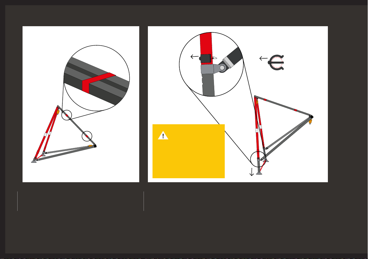
3. Fasten the two red ties around the two
U-sections tubes. Pull them tight to give
more stability.
Cross-section view
CAUTION
Only use original feet
to extend the frame.
The use of any other
feet could affect the
structural integrity.
4. The frame can be raised if required. Extend the legs by pulling the steel
clip at the base of the red section sliding into the desired hole. Secure
the feet at the desired height by putting the clip back in.

B.02 PRE-USE INSPECTION
Check the Rigging Frame thoroughly
in accordance with your training
and this manual.
If you are in any doubt about the
condition of the Rigging Frame, do
not use it and contact yourActSafe
distributor orActSafe directly.
Structure (tubes)
Check that the tubes are not damaged
in a way that it could compromise the
static strength of the frame.
»No cracks or holes
»No bending of tubes
»No indentations more
than 5mm deep
»Tubes must be round
Bolts
»Check that all bolts and eyes
are original
»Remove top bolts and check
thoroughly
»No cracks or deformations
on bolts or eyes
»Closely check the bolts
threading to ensure there is
no bending
Feet
»Check that feet are not bent,
and pivot freely
»Rubber should be present
under both feet
»No damage to tubes
»Check that both locking pins
are present and connected
to the frame
»Both feet can be easily adjusted
in height after removing pins
»Other components such as
pulleys, connector rings etc.
(see respective user manuals for
these parts)
»Annual documented inspection


APPLICATION
C
Overview and Pivoting Frame C.01
Fixed Frame C.02
Tramway Frame C.03

v
In this section, three basic
Rigging Frame applications
are shown. For more detailed
information about these
applications and the exact
setups, see the respective
sections in the manual.
CC.01 OVERVIEW AND PIVOTING FRAME
Pivoting Frame
The Pivoting Frame setup, with its inwards/
outwards pivot, is ideal for lifting a casualty
over an edge in a controlled manner.
Allow enough space for positioning and
maneuvering the frame properly in order to
benet fully from the pivoting principle.
The Frame will hold its nal, balanced,
position on the equalisation of forces alone,
with the resultant force pushing onto the
right-angle towards the feet.
C

Fixed Frame
The Rigging Frame can also be used in a xed
position with multiple guying lines. The Fixed
Frame setup allows edges to be cleared in
situations where there is little space to manage
the frame, or where the frame cannot stand on
a level surface. This setup does not have the
advantage of moving a controlled load over
the edge with the frame (as per the Pivoting
Frame setup).
C.02 FIXED FRAME
Note
Displayed are the 3 basic setups
as recommended by ActSafe, other
setups are possible but should only be
used by expert user who can ensure
the safe operation of and take the full
responsibility for that particular use.

»ww
Tramway Frame
The Rigging Frame can also be used as a
support frame for Tramway guidelines, to
facilitate further ground clearance for easier
access and exit on the Tramway. The frame
can be xed on the Tramway ropes for
improved stability.
Note
It is recommended to use the Rigging
Frame with the red side facing towards
the edge for optimal balance and
function, especially when used in the
pivoting frame setup. However, the
structural integrity of the frame is not
affected if the frame is used with the
black tubes facing towards the edge.
C.03 TRAMWAY FRAME

PIVOTING FRAME
D
Working principle,
angles and resultant forces D.01
Setup position D.02
Rigging D.03
Outward edge transition D.04
Inward edge transition D.05

Balance position
The pivoting frame will stand in
balance in its outward position,
when the angles of the ingoing
and outgoing rope are equal.
As a result, the forces that are
working will stabilise the frame
and the resultant forces point
towards the area around feet and
therefore the feet do not slip away.
D
The basic principle of the
pivoting frame is that it can
be ipped outwards/inwards
under load and will stand
in balance in its outwards
position. This working
principle is ideal for passing
edges with people or loads
with reduced effort.
D.01 WORKING PRINCIPLE, ANGLES & RESULTANT FORCES
CAUTION
Secure the feet of the
rigging frame to avoid
them slipping away.
Table of contents
Other ActSafe Safety Equipment manuals


Popular Safety Equipment manuals by other brands

Petzl
Petzl DJINN STEEL AXESS manual

Roger Technology
Roger Technology R85 Series Instruction and warnings for the installer

Dupont
Dupont ProShield 20 SFR Cat. III Instructions for use

Sabre
Sabre MK-60 Fill and Pressurization Instructions

LAS
LAS 10334 operating instructions

Troy Lee Designs
Troy Lee Designs Tbone Product owners manual


CMC
CMC HELITACK AIRBAG quick start guide

Elysee
Elysee 23415 Product information

Tractel
Tractel blocfor AES Series Operating and maintenance instructions

Tractel
Tractel FABA-Klassik A11 Operating and maintenance instructions

Protekt
Protekt P-16 instruction manual

Finsterwalder
Finsterwalder Paralock 3 instruction manual