manuals.online logo
Brands
  1. Home
  2. •
  3. Brands
  4. •
  5. ACU-RITE
  6. •
  7. Thermometer
  8. •
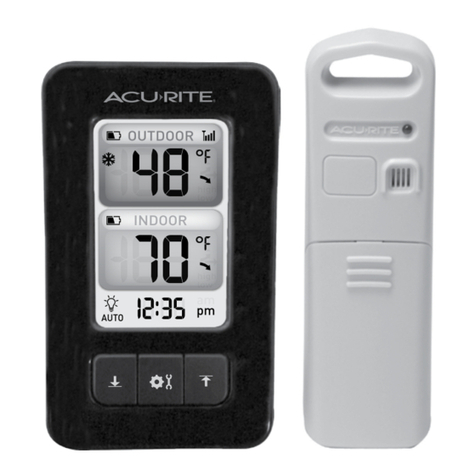
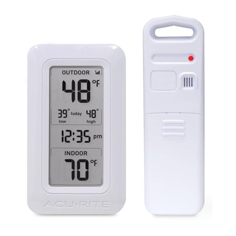
  9. ACU-RITE 00606 User manual

ACU-RITE 00606 User manual

Other ACU-RITE Thermometer manuals

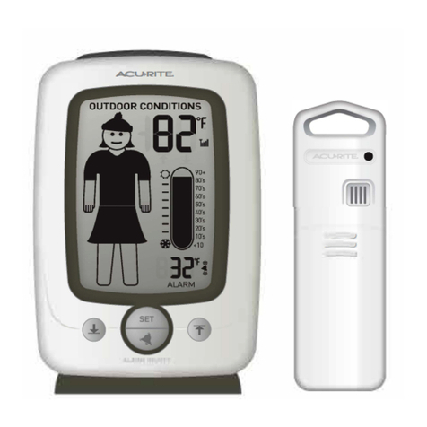
ACU-RITE 1523 User manual

ACU-RITE

ACU-RITE 1523 User manual

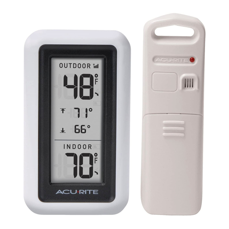
ACU-RITE 00277 User manual

ACU-RITE

ACU-RITE 00277 User manual

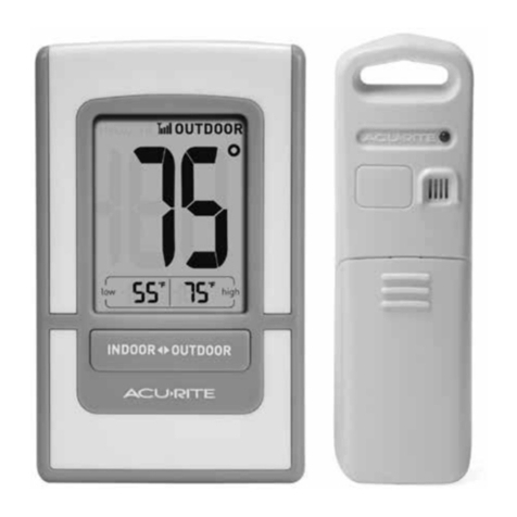
ACU-RITE 00782 User manual

ACU-RITE

ACU-RITE 00782 User manual

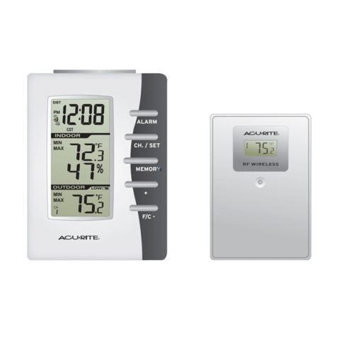
ACU-RITE 00986 User manual

ACU-RITE

ACU-RITE 00986 User manual

ACU-RITE 888 User manual

ACU-RITE

ACU-RITE 888 User manual

ACU-RITE 02097 User manual

ACU-RITE

ACU-RITE 02097 User manual

ACU-RITE 986 User manual

ACU-RITE

ACU-RITE 986 User manual

ACU-RITE 3168 User manual

ACU-RITE

ACU-RITE 3168 User manual

ACU-RITE 822 User manual

ACU-RITE

ACU-RITE 822 User manual

ACU-RITE 411 User manual

ACU-RITE

ACU-RITE 411 User manual

ACU-RITE 754 User manual

ACU-RITE

ACU-RITE 754 User manual

ACU-RITE 00592W2 User manual

ACU-RITE

ACU-RITE 00592W2 User manual

ACU-RITE 10378 Manual

ACU-RITE

ACU-RITE 10378 Manual

ACU-RITE 00384 User manual

ACU-RITE

ACU-RITE 00384 User manual

ACU-RITE 02002 User manual

ACU-RITE

ACU-RITE 02002 User manual

ACU-RITE 00305 User manual

ACU-RITE

ACU-RITE 00305 User manual

ACU-RITE 799 User manual

ACU-RITE

ACU-RITE 799 User manual

ACU-RITE 00888 User manual

ACU-RITE

ACU-RITE 00888 User manual

ACU-RITE 822 User manual

ACU-RITE

ACU-RITE 822 User manual

ACU-RITE 02044W User manual

ACU-RITE

ACU-RITE 02044W User manual

ACU-RITE 00315 User manual

ACU-RITE

ACU-RITE 00315 User manual

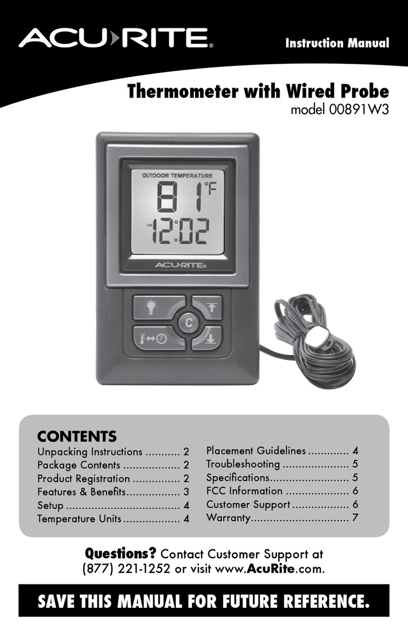
ACU-RITE 00891W3 User manual

ACU-RITE

ACU-RITE 00891W3 User manual

ACU-RITE 606 User manual

ACU-RITE

ACU-RITE 606 User manual

ACU-RITE 00526W User manual

ACU-RITE

ACU-RITE 00526W User manual

Popular Thermometer manuals by other brands

Benetech GM900 instruction manual

Benetech

Benetech GM900 instruction manual

Parton PTD-400 manual

Parton

Parton PTD-400 manual

GAME 15900 owner's manual

GAME

GAME 15900 owner's manual

scigiene FP-180 instruction manual

scigiene

scigiene FP-180 instruction manual

Ametek Land UNO U1 600/1600C-L user guide

Ametek Land

Ametek Land UNO U1 600/1600C-L user guide

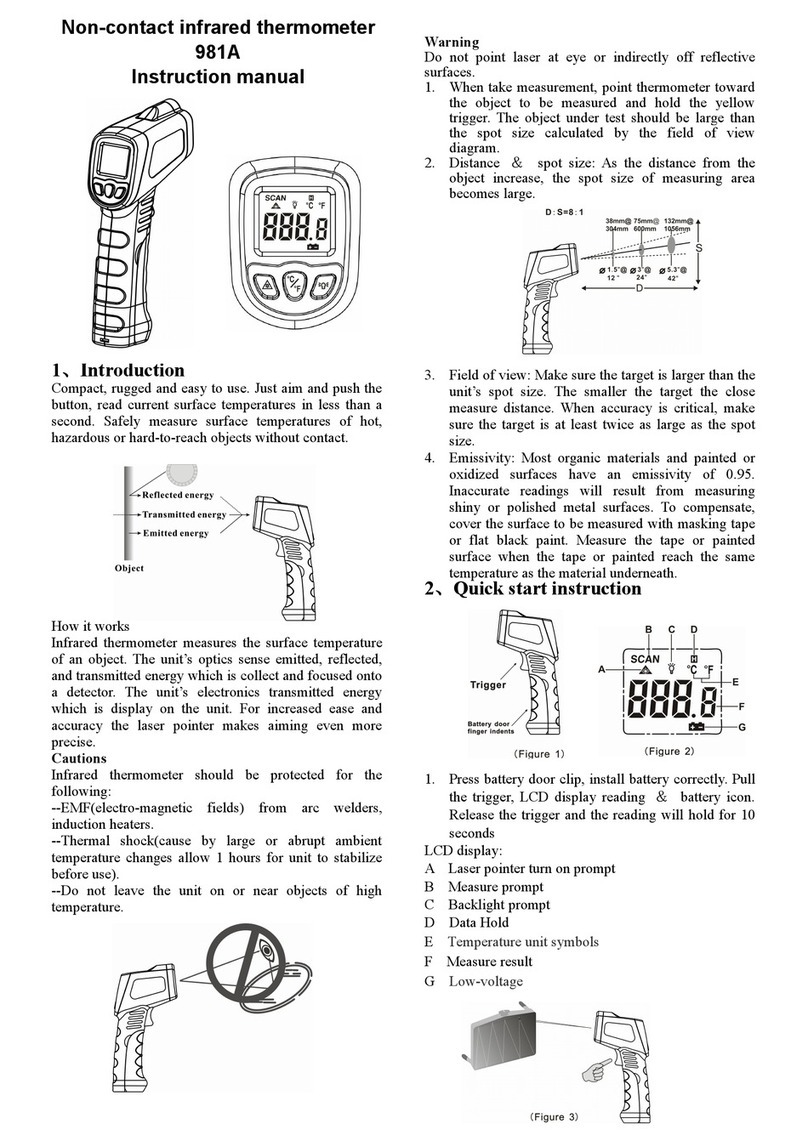
Delton 981A instruction manual

Delton

Delton 981A instruction manual

Taylor 5286498 instruction manual

Taylor

Taylor 5286498 instruction manual

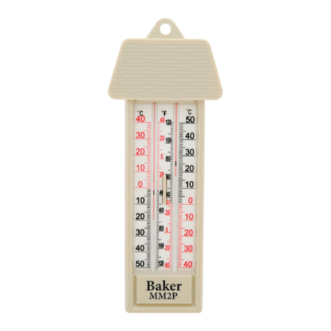
Baker MM2P instruction manual

Baker

Baker MM2P instruction manual

Chino IR-FA Series instructions

Chino

Chino IR-FA Series instructions

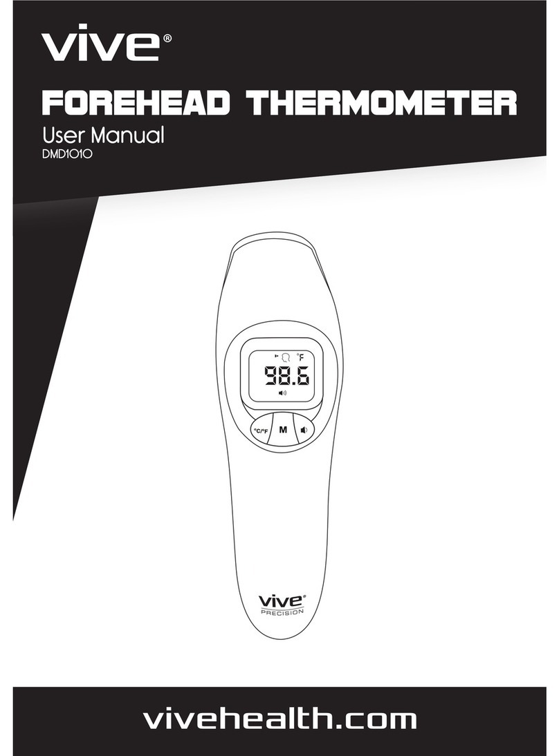
Vive DMD1010 user manual

Vive

Vive DMD1010 user manual

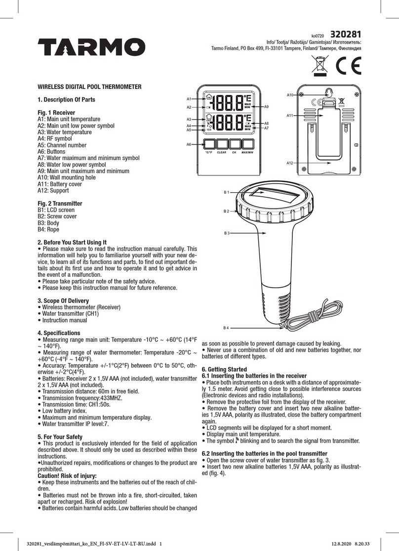
Tarmo 320281 manual

Tarmo

Tarmo 320281 manual

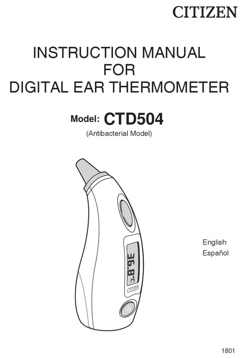
Citizen CTD 504 instruction manual

Citizen

Citizen CTD 504 instruction manual

TFA 14.1500 instruction manual

TFA

TFA 14.1500 instruction manual

Gotemp THB4002 user guide

Gotemp

Gotemp THB4002 user guide

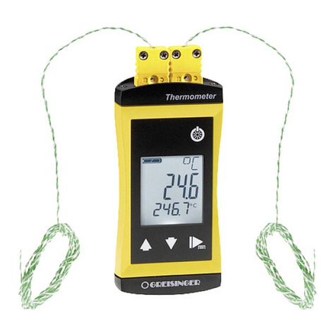
GREISINGER G 1202 Quick reference guide

GREISINGER

GREISINGER G 1202 Quick reference guide

Amprobe TMD-53W user manual

Amprobe

Amprobe TMD-53W user manual

Trotec BP10 operating manual

Trotec

Trotec BP10 operating manual

Radiance instruments RT616 Series product manual

Radiance instruments

Radiance instruments RT616 Series product manual

manuals.online logo
manuals.online logoBrands
  • About & Mission
  • Contact us
  • Privacy Policy
  • Terms and Conditions

Copyright 2025 Manuals.Online. All Rights Reserved.

INST- 00606072109
Instruction Manual
Package Contents:
DESIGNEDTOWORKFORvou· [11Main Unit [Al
[1] Wireless Sensor [Bl
[1] Instruction Manual
What You Need:
• [2] AA batteries
• [2] MA batteries
B. Wireless Sensor A. Main Unit
Thank Youfor purchasing this ACURITE® product. Please read this manual in it's
entirety to fully enjoy the benefits and features of this product. Please keep this
manual for future reference.
NOTE:A clear film is applied to the LCDat the factory that must be removed prior
to using this product. Locate the clear tab and simply peel to remove.
( 1 • OVERVIEW OF FEATURES )
Wireless Sensor
LOWBATTERY
Indicator
Outdoor Wireless Sensor
Temperature Signal Icon
Main Unit
,.,.a...-+---.-- LOWBATTERY
Indicator
°F/°C Button MIN/MAX Button
SET Button
- 1-
(SECTION 2 • SETUP )
Battery Choice & Temperature Range
Extended periods of cold temperatures Ibelow -4°F / -20°C Ican cause alkaline
batteries to function improperly. This will cause the outdoor wireless sensor to
stop transmitting temperature readings. Use lithium batteries in these low
temperature conditions to ensure continued operation for wireless sensors placed
outdoors. NOTE:Rechargeable batteries are not recommended due to higher
operating voltages.
(70°C) 158°F I
ALKALINE
BATTERIES ltWIA·i(700C) 158°F I
Install Batteries
NOTE:Install all batteries in both units within a 6 minute period to ensure proper
wireless functionality. Alwaysinstall batteries intothewireless sensorFIRST.
A.WirelessSensor 0 INSTALL2"AA"
Removethe battery 0 REMOVE • BATTERIES
BATTERY
compartment cover. COMPARTMENT
Install 2 fresh "AA" COVER
batteries as shown
here.
WirelessSensor
B.MainUnit
Removethe battery 0 REMOVE 0 INSTALL2"AAA"
compartment cover BATTERY BATTERIES
and install 2 fresh COMPARTMENT
COVER =AAAo
"AAA" batteries as OAAA=
shown here.
MainUnit
- 2 -
Basic Setup is Now Complete
The wireless sensor will soon send a signal to the main unit and the two
units will be synchronized. It may take a few minutes for synchronization to
be complete. The wirelesssensorsignal icononthe displaywill show1to4 "bars"
whenthe signalis received.If both or one of the units appear to be functioning
improperly, refer to the troubleshooting section in this manual.
Main Unit : Clock Set
After installing batteries into the Wireless Sensor and into the Main Unit, the
clock can be set.
TOSETTHE CLOCK:
Press andholdthe "SET" button for 5 seconds to enter into CLOCKSETMODE.
Oncein clock set mode, the preference you are currently setting will blink on the
display.
The preference set order is as follows:
CLOCKHOURMODE(12 hour or 24 hour)
CLOCKHOUR
CLOCKMINUTE
Toadjustthe currently selected (flashing) preference item, press the"+" button
to adjust up to the desired setting (press and HOLDto fast adjust). Tosaveyour
adjustments, press the "SET" button again to move on to adjusting the next
preference.
Youwill automatically exit CLOCKSETMODEif no buttons are depressed for :30
seconds. Youmay enter basic setup mode again at any time by pressing and
holdingthe "SET" button.
Main Unit: MIN/MAX Memory
This wireless thermometer features a MIN/MAX memory feature which records
the MINIMUM and MAXIMUMindoor and outdoor temperature readings.
Toview the MAXrecorded temperature reading, press and release the
"MIN/MAX" button. Note the "MAX" icon on the display.
Toview the MIN recorded temperature reading, press and release the
"MIN/MAX" button again. Note the "MIN" icon on the display.
Toclear the MAXrecorded values, press andholdthe "MIN/MAX" button while
in the MAXview mode. Dasheswill display in the temperature display to confirm
you have cleared the MAXvalues.
Toclear the MIN recorded values, press andholdthe "MIN/MAX" button while in
the MIN view mode. Dasheswill display in the temperature display to confirm
you have cleared the MIN values.
- 3 -
(SECTION 3 • PLACEMENT )
Now that setup is complete, you must choose a location to place the wireless
sensor and the main unit. The wireless sensor MUSTbe placed less than 100
feet away from the main unit.
This wireless thermometer uses radio frequency for communication, which is
susceptible to interference from other electronic devices and large metallic
items or thick walls. Always place both units at least 3 feet away from
appliances ITV,microwave, radios, computers, etc. I or objects that may
interfere with the wireless communication Ilarge metal surfaces, thick stone
walls, etc. ].
--'01'.,.
- -
,; I \'
100 feet maximum
Placement of Main Unit
Place the main unit in a dry area free of dirt and dust. Tohelp ensure
an accurate indoor temperature measurement, be sure to place the
main unit out of direct sunlight, and away from any heat sources or
vents in your home. There are 2 placement options for the main unit.
Youmay hang the main unit on a wall using the integrated hang hole.
Alternatively, you may place the main unit on a table top or other flat
surface.
Placement of Sensor
The wireless sensor MUSTBE PLACEDOUTDOORSto observe
outdoor temperatures. The wireless sensor must be placed less than
100feet from the main unit.
The wireless sensor is water resistant and is designed for general
outdoor use. However, to extend the life of the product, place the
wireless sensor in an area protected from direct weather elements.
Toensure an accurate outdoor temperature measurement, be sure
the wireless sensor is placed out of direct sunlight and awayfrom any
heat sources.
There are 2 placement options for the wireless sensor. Youmay hang
it on a wall using one of the two integrated hang holes, or use string
[not included] to hang it from a suitable location like a well covered
tree branch.
-4 -
Troubleshooting
Problem Possible Solution
Bad
Wireless Sensor
Reception
(no temperature reading)
,OF
• Make certain that the batteries are installed
correctly into the wireless sensor. The
wireless sensor batteries may need
replacing.
• Relocate the main unit and/or the wireless
sensor. Both units must be within 100feet
from each other.
• Make sure both units are placed at least 3
feet from other electronic appliances and
devices that may interfere with the wireless
communication [such as TV's, microwaves,
radios, computers etcl.
• Make certain there are no large metallic
Tull
--out 1..olllll
no bars
12:35pm
surfaces or very thick stone walls or surfaces
between the wireless sensor and the main
unit.
,noF.
IU 1n
• Metal screens or LOW-Ewindows may
interfere with the wireless communication.
• In some cases, relocating AND resetting
the main unit and wireless sensors
[removing and re-installing batteries) may be
necessary.
NOTE:It may take up to 20 minutes for the
main unit to re-synchronize with the sensor
when batteries are replaced. Use lithium
batteries in sensor when temperature is
below -4°F.
Main Unit
Display Not Working Make certain that the batteries are installed
correctly. The batteries may need replacing.
Please DO NOT return product to the retail store.
For technical assistance and product return information, please call
Customer Care: 877-221-1252 Mon. - Fri. 8:00A.M. to 4:45 P.M.(CST]
www.chaneyinstrument.com
-5 -
(SECTION 4 • PRODUCT SPECIFICATIONS
Measurement Ranges
Temperature
MainUnit:32°Fto 122°F / o0cto 50°C
Wireless Sensor: -40°F to 158°F / -40°Cto 70°C
Specifications
Power Requirements
Main Unit: 2 x "AAA" alkaline or lithium batteries
Wireless Sensor: 2 x "AA" alkaline or lithium batteries
Wireless Communication
Radio Frequency: 433 mhz
Transmission Intervals: every 16 seconds
PLEASEDISPOSEOFOLDORDEFECTIVEBATTERIESINANENVIRONMENTALLYSAFE
WAYANDIN ACCORDANCEWITHYOURLOCALLAWSANDREGULATIONS.
BATTERYSAFETY:Followthepolarity(+/-)diagraminthebatterycompartment.Promptlyremovedeadbatteriesfromthe
device.DisP-oseofusedbatteriesproperly.Onlybatteriesofthesameorequivalenttypeasrecommendedaretobe
used.DONOTincinerateusedbatteries.DONOTdisposeofbatteriesinfire,asbatteriesmayexplodeorleak.DONOTmix
oldandnewbatteriesortypesofbatteries(alkaline/standard).DONOTuserechargeablebatteries.DONOTrecharge
non-rechargeablebatteries.DONOTshort-circuitthesupplyterminals.
- 6 -
] Toreceiveproduct information, register your product online. Ifs quick and easy!
Log on to http://www.chaneyinstrument.com/product_reg.htm
LIMITEDONEYEARWARRANTY
Chaney Instrument Company warrants that all products it manufactures to be of good material and workmanship and to be free of
defects if properly installed and operated for a period of oneyear from dateof purchase. REMEDYFORBREACHOFTHIS
WARRANTYISEXPRESSLYLIMITEDTOREPAIRORREPLACEMENTOFDEFECTIVEITEMS.Any product which, under normal use
and service, is proven to breach the warranty contained herein within ONE YEARfrom date of sale will, upon examination by
Chaney,and at its sole option, be repaired or replaced by Chaney. In all cases, transportation costs and charges for returned
goods shall be paid for by the purchaser. Chaney hereby disclaims all responsibility for such transportation costs and charges.
This warranty will not be breached, and Chaney will give no credit for products it manufactures which shall have received normal
wear and tear, been damaged, tampered, abused, improperly installed, damaged in shipping, or repaired or altered by others than
authorized representatives of Chaney.
THEABOVE-DESCRIBEDWARRANTYISEXPRESSLYIN LIEUOFALL OTHERWARRANTIES,EXPRESSORIMPLIED,ANDALL
OTHERWARRANTIESAREHEREBYEXPRESSLYDISCLAIMED,INCLUDINGWITHOUTLIMITATIONTHEIMPLIEDWARRANTYOF
MERCHANTABILITYANDTHE IMPLIEDWARRANTYOFFITNESSFORA PARTICULARPURPOSE.CHANEYEXPRESSLYDISCLAIMS
ALL LIABILITYFORSPECIAL,CONSEQUENTIALORINCIDENTALDAMAGES,WHETHERARISINGINTORTORBYCONTRACTFROM
ANYBREACHOFTHISWARRANTY.SOMESTATESDONOTALLOWTHEEXCLUSIONORLIMITATIONOFINCIDENTALOR
CONSEQUENTIALDAMAGES,SOTHEABOVELIMITATIONOREXCLUSIONMAYNOTAPPLYTOYOU.CHANEYFURTHERDISCLAIMS
ALL LIABILITYFROMPERSONALINJURYRELATINGTOITSPRODUCTSTOTHEEXTENTPERMITTEDBYLAW. BYACCEPTANCE
OFANYOFCHANEY'SEQUIPMENTORPRODUCTS,THEPURCHASERASSUMESALL LIABILITYFORTHECONSEQUENCES
ARISINGFROMTHEIRUSEORMISUSE.NOPERSON,FIRMORCORPORATIONISAUTHORIZEDTOASSUMEFORCHANEYANY
OTHERLIABILITYIN CONNECTIONWITHTHESALEOFITSPRODUCTS.FURTHERMORE,NOPERSON,FIRMORCORPORATIONIS
AUTHORIZEDTOMODIFYORWAIVETHETERMSOFTHISPARAGRAPH,ANDTHEPRECEDINGPARAGRAPH,UNLESSDONEIN
WRITINGANDSIGNEDBYA DULYAUTHORIZEDAGENTOFCHANEY.THISWARRANTYGIVESYOUSPECIFICLEGALRIGHTS,AND
YOUMAYALSOHAVEOTHERRIGHTSWHICHVARYFROMSTATETOSTATE.
For in-warranty repair, please contact:
Customer CareDepartment
Chaney Instrument Company
965Wells Street
LakeGeneva,WI 53147
ChaneyCustomerCare
877-221-1252
Mon-Fri8:00a.m.to4:45p.m.CST
www.chaneyinstrument.com
This device complies with part 15 of the FCCrules. Operation is
su~ect to the following_two conditions:
1-This device may NOTcause harmful interference, and
Fe 2- This device must accept any interference received, including
interference that may cause undesired operation.
NOTE:This equipment has been tested and found to comply with the limits for a
Class B digital device, pursuant to Part 15of the FCCrules. These limits are
designed to provide reasonable protection against harmful interference in a residential installation.
This equipment generates, uses and can radiate radio frequency energy and, if not installed and used
in accordance with the instructions, may cause harmful interference to radio communications.
However, There is no guarantee that interference will not occur in a particular installation. If this
equipment does cause harmful interference to radio or television reception, which can be determined
byturning the equipment off and on, the user is encouraged to try to correct the interference byone or
more of the following measures:
• Reorient or relocate the receiving antenna.
• Increase the separation between the equipment and the receiver.
• Corne<=;tthe equipment into an outlet on a circuit different from that to which the
receiver 1sconnected.
• Consult the dealer or an experienced radio/TV technician for help.
NOTE:The manufacturer is not responsible for any radio or TVinterference caused by unauthorized
modifications to this equipment. Such modifications could void the user authority to operate the
equipment.
Patent numbers: 5,978,738; 6,076,044; 6,597,990
- 7 -