Adash VA5 Pro User manual

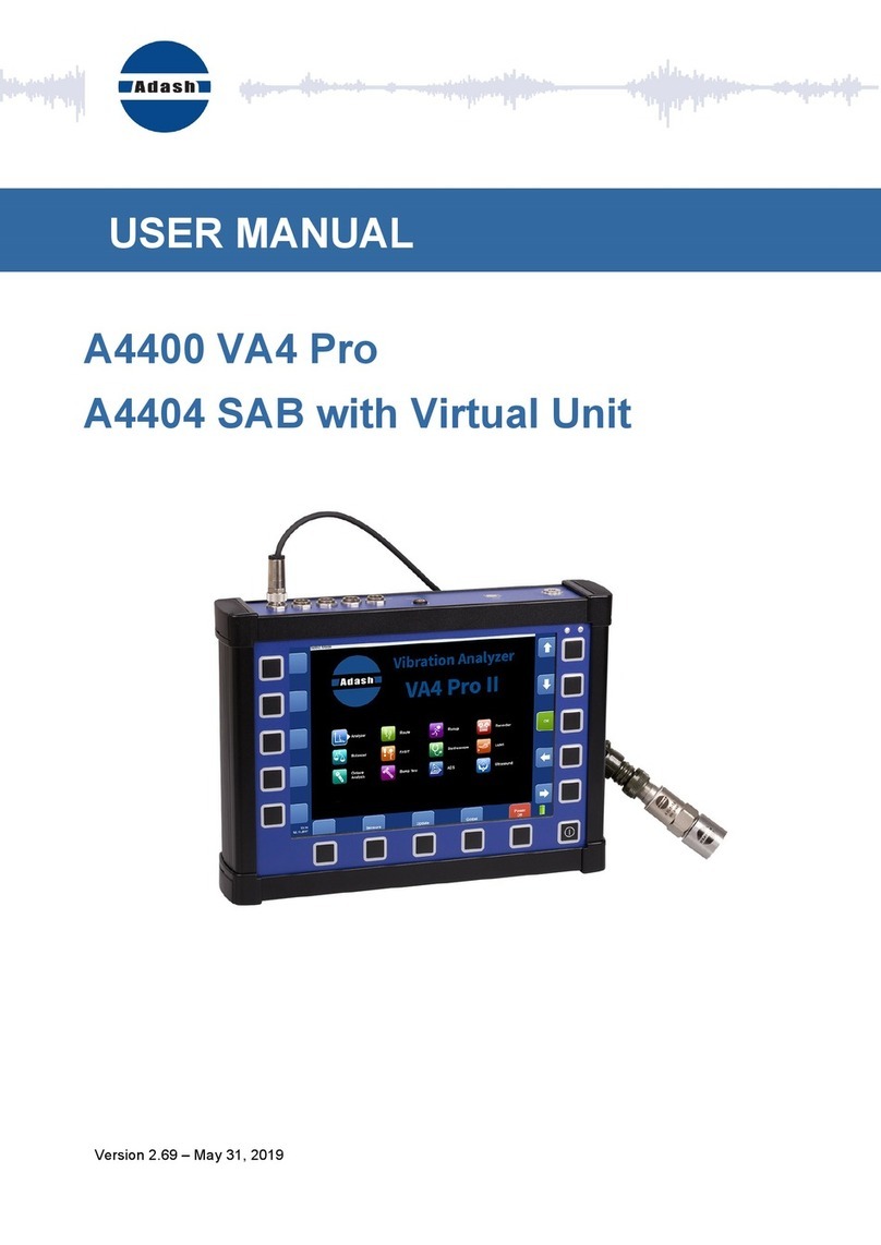
USER MANUAL
VA5 Pro
A4404 SAB
Virtual Unit
Version 2.69 – July 01, 2019

ADASH Adash 4500 – VA5Pro
For further technical and contact information visit www.adash.com or email: [email protected]
2
Content:
VA5 Pro vs. A4404 SAB.......................................................................................... 12
VA5 Pro...........................................................................................................................12
A4404 SAB (Signal Analyzer Box)................................................................................... 12
Before Switching On............................................................................................... 13
General Warnings ........................................................................................................... 13
General Information................................................................................................ 14
Front View.......................................................................................................................14
Top View .........................................................................................................................14
Rear View........................................................................................................................14
Battery Charging ............................................................................................................. 15
Switching on....................................................................................................................15
Switching off....................................................................................................................15
Sleep Mode ..................................................................................................................... 16
Auto Switch off ................................................................................................................ 16
Emergency Switch off...................................................................................................... 16
Capacity Warning............................................................................................................ 16
Connection to the computer............................................................................................. 16
VA5_DISC 16
Connection 16
VAx_DISC 17
Input Channels........................................................................................................ 18
IN1 Socket....................................................................................................................... 18
IN2 Socket....................................................................................................................... 18
IN3 Socket....................................................................................................................... 19
IN4 Socket....................................................................................................................... 19
TRIG Socket....................................................................................................................19
Standard Cable Wiring ....................................................................................................20
A4409 - BNC Box .................................................................................................... 21
Instrument Control.................................................................................................. 22
How to work with menu ...................................................................................................22
Item Selection 22
Value Selection 23
User Defined Values 23
Item Value Saving 24
Multi-selection of Items 24
Searching an Item 24
Main Screen............................................................................................................. 25
Modules .......................................................................................................................... 25
MENU button................................................................................................................... 25
Shortcuts......................................................................................................................... 25
Battery Lifetime ............................................................................................................... 25
PC Connection Indication ................................................................................................26
MENU ....................................................................................................................... 27
MENU / SETTINGS .................................................................................................. 28
Global Settings................................................................................................................28
Display Route Values 28
Route Autosave 28
Route Auto Forward 28
Check Route Sensors 28
Display Small Values 28
Stop if ICP Error 28

ADASH Adash 4500 – VA5Pro
For further technical and contact information visit www.adash.com or email: [email protected]
3
Units 28
Frequency unit 29
Speed unit 29
Power/Line Frequency 29
Phase range 29
Displayed Spectra in Cascade 29
Align Graphs 29
Graph Grid 29
Cursor Type 29
Record analysis speed 29
Record Analysis Start 29
Touchscreen ................................................................................................................... 30
Enable Touchscreen 30
Keyboard.........................................................................................................................30
Keyboard Backlight 30
Language ........................................................................................................................ 30
Language 30
Brightness ....................................................................................................................... 30
Appearance.....................................................................................................................30
Interface Style 30
Background Color 30
Profiles ............................................................................................................................30
Save settings to "just opened profile name" 31
Save settings as new profile 31
Factory 31
List of saved profiles 31
User Notes Settings ........................................................................................................ 31
Date/Time........................................................................................................................32
Date format 32
Year, Month, Day, Hour, Minute, Second 32
Shortcuts......................................................................................................................... 32
Signal Source.................................................................................................................. 33
Trigger Settings............................................................................................................... 33
Trigger Mode 33
Runup Mode 33
Speed change 33
Time change 33
Trigger Source 33
Use Ampl Tacho 34
Ampl Trig Channel 34
Ampl Trig Level 34
Ampl Tacho Hysteresis 34
External Trig Edge 34
External Trig Level[V] 34
Pretrig (%) 34
Runup ............................................................................................................................. 35
Max Memory Size [MB] 35
Time Unit 35
Length 35
Trend Time Axe 35
Trend Length 35
Spectrum Settings........................................................................................................... 35
Detect Type 35
Axe X 36
Axe Y 36
Peaks list 36
Graph Lines 36
Sensors........................................................................................................................... 36

ADASH Adash 4500 – VA5Pro
For further technical and contact information visit www.adash.com or email: [email protected]
4
Sensor Properties for Records 36
AC Sensors..................................................................................................................... 37
ICP 37
Sensitivity[mV/unit] 37
Unit 37
Position 37
DC gap channel 37
ISO Machine Group 37
Bearing Type 37
ISO 10816 Machine Groups ............................................................................................ 38
Bearing Settings.............................................................................................................. 38
Bearing type 38
Rotating Race 38
DC Sensors.....................................................................................................................38
Sensitivity [mV/unit] 38
Offset [mV] 38
Unit 38
Position 39
Tacho.............................................................................................................................. 39
Tacho Trig Level 39
Pulses per rotation 39
Min Speed 39
Settling Prolongation ....................................................................................................... 39
MENU / RUN ............................................................................................................ 40
Camera ........................................................................................................................... 40
IR Camera....................................................................................................................... 40
Gallery.............................................................................................................................40
Update ............................................................................................................................ 40
Help................................................................................................................................. 40
Screenshot...................................................................................................................... 40
Export All.........................................................................................................................40
About............................................................................................................................... 40
Power Off ........................................................................................................................ 41
Speed detection ...................................................................................................... 42
Analyzer................................................................................................................... 43
Meas ............................................................................................................................... 43
Graph..............................................................................................................................43
Set................................................................................................................................... 43
Reading...........................................................................................................................43
Project............................................................................................................................. 43
Export of the Project to the VA5_DISC (flash disc)..........................................................43
Project List ...................................................................................................................... 44
Project Menu ...................................................................................................................44
New Project - Set creation 44
New Project - L1/Set creation 45
New Project - L2/L1/Set creation 45
Copy 46
Rename 46
Delete 46
Clear Data 46
Notes 46
Export 46
Export to runup 46
Main Set Screen..............................................................................................................46
Measurement Definition in the Set................................................................................... 47
Input Buffering.................................................................................................................52

ADASH Adash 4500 – VA5Pro
For further technical and contact information visit www.adash.com or email: [email protected]
5
Graph Max/Min................................................................................................................52
Graphs Control................................................................................................................52
Set Menu.........................................................................................................................54
Save data 54
Notes 54
Clear Data 54
Enter speed / Cancel speed 54
View Trend / View Actual 55
Clear Last Data 55
Meas Menu ..................................................................................................................... 55
New Basic 55
New Advanced 56
Copy 56
Info 56
Edit 56
Delete 56
Export to uff 56
Export to wav 56
Export to csv 57
Export to csv (all) 57
Export to Records 57
Export to VA5_DISC 57
Edit Measurement ........................................................................................................... 57
Type 57
Channel 57
Unit 57
Detect Type 57
Result Type 58
Band fmin 58
Band fmax 58
DEMOD fmin 58
DEMOD fmax(Hz) 58
Input channel 59
Output channel 59
FFT Window 59
Zoom spectrum 60
Center freq 60
Range 60
ACMT FS 60
Trigger control 60
Number of triggers 60
Samples 61
Lines 61
Orders 61
Avg 61
Averaging 61
Overlap 61
Resolution 61
Frequency 61
Full spectrum 61
Graph Properties............................................................................................................. 62
Display 62
Scale 62
Cursor (for time signals) 62
Cursor (for spectra) 62
Cursor Position 62
Delta X 62
Axe X 63

ADASH Adash 4500 – VA5Pro
For further technical and contact information visit www.adash.com or email: [email protected]
6
Axe Y 63
Axe Z 63
Order Z 63
Detect Type 63
Peaks List 63
Synch Table 63
Bearing Faults 63
Orders Table 64
Statistics Table 64
Primary Cursor 64
View (for center line) 64
View (for frf) 64
View (for 1x amp+phase) 65
View (for phase shift) 66
View (for spectrum) 67
View (for spectrum) 67
View (for time waveform) 67
View (for orbit) 67
View (for filtered orbit) 67
FFT Output (for spectrum) 68
Speed Period 68
FTF Period 68
BSF Period 68
BPFO Period 68
BPFI Period 68
Graph Lines 68
FASIT.............................................................................................................................. 69
Overall............................................................................................................................. 69
ISO 10816 overall measurement 70
Spectrum.........................................................................................................................71
Full spectrum 71
Time................................................................................................................................73
Time signal averaging 74
Time signal with DC offset (gap) 74
G-demod Spectrum......................................................................................................... 75
G-demod Time ................................................................................................................ 75
G-demod Overall............................................................................................................. 76
1x amp+phase................................................................................................................. 76
Orbit ................................................................................................................................ 77
Orbit measurement with DC offset (gap) 77
Filtered Orbit ................................................................................................................... 78
Speed..............................................................................................................................78
ACMT.............................................................................................................................. 79
Orders............................................................................................................................. 80
Order Spectrum (Order Tracking Analysis)...................................................................... 80
Order full spectrum 81
Phase Shift......................................................................................................................81
DC................................................................................................................................... 81
Frf - Frequency Response Function ................................................................................ 82
Octave Spectrum, Sound Level and Equivalent Sound Level .......................................... 83
Center Line...................................................................................................................... 83
S-max.............................................................................................................................. 84
Cepstrum......................................................................................................................... 85
Ultrasound....................................................................................................................... 85
Record ............................................................................................................................ 86
Route........................................................................................................................ 87
Loading of the route to the instrument ............................................................................. 87

ADASH Adash 4500 – VA5Pro
For further technical and contact information visit www.adash.com or email: [email protected]
7
Creation of the route tree................................................................................................. 87
Route Measurement........................................................................................................ 87
Reference Values............................................................................................................89
Manual Entry ...................................................................................................................89
Enter Speed .................................................................................................................... 90
Cancel Speed.................................................................................................................. 90
Notes...............................................................................................................................90
Speed in the Route.......................................................................................................... 92
Speed entered in the instrument 92
Speed entered in DDS 92
Measured Speed 92
Export to VA5_DISC........................................................................................................ 92
Runup ...................................................................................................................... 93
Measurement Control...................................................................................................... 93
Runup Measurement....................................................................................................... 93
Trends............................................................................................................................. 94
Trend Menu.....................................................................................................................96
Delete 96
Export 96
Recorder .................................................................................................................. 97
Project List ...................................................................................................................... 97
Project Menu ...................................................................................................................97
New 98
Copy 98
Rename 98
Delete 98
Clear Data 98
Notes 98
Export 98
Export to wav 98
Export to wav Settings 98
Record Settings............................................................................................................... 99
Sampling Frequency 99
AC1 – AC4, DC1 – DC4, Trigger Channel 99
Time 99
Start of Rec 99
Pretrig 100
Recording...................................................................................................................... 100
Record Preview............................................................................................................. 101
Export to wav ................................................................................................................ 101
AC1 – AC4 102
Mixer 102
Range [V] 102
Temporary records........................................................................................................ 102
Balancer................................................................................................................. 103
Introduction ................................................................................................................... 103
Project........................................................................................................................... 103
Project Screen............................................................................................................... 103
Project List .................................................................................................................... 103
New 104
Copy 104
Rename 104
Delete 104
Clear Data 105
Export 105
New project ................................................................................................................... 105

ADASH Adash 4500 – VA5Pro
For further technical and contact information visit www.adash.com or email: [email protected]
8
Balancer Settings .......................................................................................................... 105
Basic Settings ............................................................................................................... 105
Planes 105
Image 106
Look 106
Rotation 106
Inputs 106
Channel 106
Channel A, Channel B 106
Balancing Masses 106
Blades 106
Meas Mode 106
Avg 106
Resolution 106
Units Settings ................................................................................................................ 107
Amplitude 107
Detect Type 107
Speed 107
Mass 107
Rotor Settings ............................................................................................................... 107
Rotor Mass 107
Correction Radius 107
Balance Quality Grade 107
Single Plane Balancing.................................................................................................. 108
RUN 1 Screen 108
RUN 2 - TRIAL MASS Screen 108
RUN 2 - RESULT Screen 110
RUN 3 Screen 113
Trim Screens 113
Dual Plane Balancing .................................................................................................... 114
RUN 1 Screen 114
RUN 2 with trial mass in plane 1 115
RUN 2 with trial mass in plane 2 117
RUN 2 - Result Screen 118
RUN 3 Screen 118
Trim Screens 118
Balancing Errors............................................................................................................ 118
The effect of trial weight is low 119
Balancer Menu .............................................................................................................. 119
Balancing Report 119
Balancing Vectors 119
Total Mass 120
FASIT ..................................................................................................................... 121
Setup............................................................................................................................. 121
Channel 121
Band fmin [Hz] 121
Sensor Settings............................................................................................................. 121
Units.............................................................................................................................. 121
metric 121
imperial: 121
Measurement ................................................................................................................ 121
FASIT screen ................................................................................................................ 122
Vibration Limits.............................................................................................................. 122
Machine Limits .............................................................................................................. 123
Bearing Limits ............................................................................................................... 124
Unbalance, Misalignment and Looseness ..................................................................... 124
Stethoscope .......................................................................................................... 125

ADASH Adash 4500 – VA5Pro
For further technical and contact information visit www.adash.com or email: [email protected]
9
The delay of audio output .............................................................................................. 125
Playback Settings.......................................................................................................... 125
Playback speed 125
Stereo 126
Lubri - the greasing control ................................................................................. 127
Two Possible Ways How to Measure ............................................................................ 127
Procedure...................................................................................................................... 128
Octave Analysis .................................................................................................... 130
Measurement settings ................................................................................................... 130
Type 130
Channel 130
Unit 130
Resolution 130
Frequency Range 130
Frequency Weighting 130
Averaging 131
Avg 131
Measurement ................................................................................................................ 131
Octave Analysis Algorithm............................................................................................. 131
Bump Test ............................................................................................................. 132
Settings ......................................................................................................................... 132
Channel 132
Hits 132
Amplitude Trigger.......................................................................................................... 132
Response Spectrum...................................................................................................... 133
Analysis......................................................................................................................... 134
Buttons.......................................................................................................................... 134
Start 134
New test 134
Export 134
ADS ........................................................................................................................ 135
ADS project................................................................................................................... 135
Project Import to VA5 135
Rewriting of geometry 135
Project List .................................................................................................................... 135
Project Menu ................................................................................................................. 135
Copy 136
Rename 136
Delete 136
Clear Data 136
Export Data 136
Export Project 136
ADS Settings................................................................................................................. 136
Measurement Definition 137
Reference Direction 137
Frequency for Animation 137
Views ............................................................................................................................ 137
Machine View 137
Measurement View 138
Machine+Measurement View 139
Automatic change of view 139
Buttons for Machine View.............................................................................................. 139
Fit 139
Start/Stop Animation 139
Enter Direction 139

ADASH Adash 4500 – VA5Pro
For further technical and contact information visit www.adash.com or email: [email protected]
10
Blink on/Blink off 139
Hide on/Hide off 139
Zoom 140
Left / Right Arrow - Direction 140
Up / Down Arrow - Point 140
Start 140
Buttons for Measurement View...................................................................................... 140
Zoom 140
Graph Properties 140
180° on/180°off 140
Save 140
Ultrasound............................................................................................................. 141
Introduction ................................................................................................................... 141
Sensor Setting............................................................................................................... 141
Settings ......................................................................................................................... 141
Measurement ................................................................................................................ 142
Listening........................................................................................................................ 142
Camera................................................................................................................... 143
Buttons.......................................................................................................................... 143
Pause / Run 143
Capture 143
Gallery 143
IR Camera .............................................................................................................. 144
Cursor ........................................................................................................................... 144
Buttons.......................................................................................................................... 144
Pause / Run 144
Capture 144
Gallery 144
Graph Properties........................................................................................................... 145
Unit 145
Emissivity 145
Color spectrum 145
Scale 145
Gallery.................................................................................................................... 146
Buttons.......................................................................................................................... 146
Sort 146
Delete 146
Buttons for maximized IR Camera picture ..................................................................... 147
Cursor 147
Graph Properties 147
A4404 SAB and Virtual Unit ................................................................................. 148
Installation..................................................................................................................... 148
A4404 SAB Drivers Installation 148
Virtual Unit Installation 148
License file 148
Update .......................................................................................................................... 148
Operation ...................................................................................................................... 148
VA5_DISC..................................................................................................................... 149
VA5 Virtual unit and VA5 Pro connection....................................................................... 149
Copying projects to the instrument 149
Projects and records copy from the instrument 149
Appendix A: Technical Specification.................................................................. 150
Inputs ............................................................................................................................ 150
Dynamic Channels (AC) 150

ADASH Adash 4500 – VA5Pro
For further technical and contact information visit www.adash.com or email: [email protected]
11
Tacho Channel 150
Static Channels (DC or 4-20mA) 150
Measurement Functions................................................................................................ 150
Recording:..................................................................................................................... 151
Balancing: ..................................................................................................................... 151
General: ........................................................................................................................ 151
Appendix B : Phase measurement conventions................................................ 152
Single channel measurement with tacho ....................................................................... 152
Dual channel measurement........................................................................................... 155
Last reminder ................................................................................................................ 155
Appendix C: Symbols and Abbreviations........................................................... 156
Abbreviations in Graphs ................................................................................................ 156

ADASH Adash 4500 – VA5Pro
For further technical and contact information visit www.adash.com or email: [email protected]
12
VA5 Pro vs. A4404 SAB
The VA5 Pro instrument, the A4404 SAB Signal Analyzer Box and the Virtual Unit application will be described
in this user manual. This chapter should clear up the difference between them.
VA5 Pro
VA5 Pro is a portable vibration analyzer which is based on unique Digital Signal Processing board (DSP)
developed by Adash.
A4404 SAB (Signal Analyzer Box)
A4404 SAB is a pocket size vibration analyzer which contains input connectors for sensors. It uses the same
DSP board as VA5 Pro but it doesn't contain keyboard and screen. It must be connected with computer via
USB. You need to install Virtual Unit application which is the same software used in VA5 Pro. Almost all
functions described in this manual work both in the instrument and in the Virtual Unit. You will be notified when
some difference occurs. Virtual Unit and A4404 SAB peculiarities will be described in a standalone chapter in
the end of the manual.

ADASH Adash 4500 – VA5Pro
For further technical and contact information visit www.adash.com or email: [email protected]
13
Before Switching On
General Warnings
Only suitable ICP powered sensors can be connected to the AC signal inputs.
If the measurement without ICP power is required, ICP power must be switched off. You can damage the
external signal source, which is not protected against ICP powering.
AC channels - voltage higher then 18 V (peak) can damage the instrument.
DC channels - voltage higher then 30 V (peak) can damage the instrument.
Always use only original cables designed for connection with sensor.
Long push and hold of POWER button evokes incorrect instrument switching off. Data could be lost.
If you are unsure, contact your distributor or the manufacturer.
Ignoring an
y recommendations mentioned below may cause failure of the device.
Operating with a power higher then 24 V can cause an accident.

ADASH Adash 4500 – VA5Pro
For further technical and contact information visit www.adash.com or email: [email protected]
14
General Information
Front View
Top View
Rear View

ADASH Adash 4500 – VA5Pro
For further technical and contact information visit www.adash.com or email: [email protected]
15
Battery Charging
Charge the battery only at 0 - 40°C (30 - 100 °F)!
The POWER socket for external charger is on the top panel. The battery LED diode lights orange during
charging and lights green when fully charged.
The VA5 instrument uses Li-ION (LiON) batteries. This type of battery should not be discharged completely. If
the battery is discharged below certain Voltage, we call it deep discharging. The deep discharging shortens
battery life. The charging of deeply discharged battery takes much longer.
If the instrument is not charged for longer period of time, then the deep discharge can occur. It is caused by self-
discharging of the battery. Another cause of deep discharge can be a situation when the instrument is switched
to the SLEEP mode by the Power Off button (instead of switching off the instrument). When the battery is
deeply discharged, it takes much longer to charge it again. Sometimes the indicator on the charger does not
light when the battery is deeply discharged – it does not mean it is not charging. Please keep the battery
charging even if the indicator does not light, the indicator will start light later.
To avoid deep discharge of the instrument, charge it regularly, even when you don’t use it. We recommend you
to check if it is charged every 3 months.
WHAT TO DO WHEN YOU CANNOT SWITCH ON THE INSTRUMENT/ WHEN THE INSTRUMENT CANNOT
BE CHARGED NORMALLY:
- Discharged battery – battery needs to be charged (charging for approximately 5 hours), the instrument
can be switched on normally with the charger connected
- Deeply discharged battery, when the instrument wasn’t charged for longer period of time – the
instrument needs to be charged completely until the indicator on the charger starts light green. It can
take more than 12 hours. The indicator on the charged does not light from the beginning of charging
process. Sometimes it is not possible to switch on the instrument even with the charger connected.
- Damaged charger – when the charger is connected, the indicator should start to light (green or orange
color), only with deep discharge the indicator does not light immediately.
- Sudden decrease of battery life – the instrument needs to be charged and discharged completely few
times (usually 2-5 times). The battery lifetime should increase this way.
Switching on
The POWER button is in bottom left corner of the front panel. Press the button for a few seconds until a power
LED begins to light. Firstly it blinks orange for a while, then it lights blue. A keyboard backlight blinks for a while.
Switching off
Use a Power Off in main MENU and confirm.
Warning! The POWER button (intended for the switching on) doesn't turn the instrument off. It switches it into a
sleep mode!

ADASH Adash 4500 – VA5Pro
For further technical and contact information visit www.adash.com or email: [email protected]
16
Sleep Mode
Use the POWER button (described in the "Switch on" chapter) to switch the instrument into a sleep mode. The
screen is off and power consumption is lower in the sleep mode. Use the same POWER button to wake up
again.
Note! You can use any button to wake the instrument up. However notice the button press isn't ignored by the
system even in the sleep mode and the press can cause some unexpected event in the application. The
reaction to the button press is same like not being in the sleep mode.
Auto Switch off
If no button is pushed in 5 minutes from switching on, the instrument will be switched off.
Emergency Switch off
This is not correct method to switch off the instrument. Using it can cause data corruption. Use this method only
in case of emergency (eg. when the system freezes).
Push and hold the POWER button for about 10 seconds. Instrument will switch off.
Capacity Warning
If this warning message appears, you need to get free disc space by removing the measurements, routes or
records, which are not needed.
Connection to the computer
VA5_DISC
All data like projects, measurements, readings, setups and so on are stored to a high capacity hard disk which
is intended for internal purposes only. Furthermore the instrument contains the VA5_DISC, it is flash memory,
which is accessible from external computer. The VA5_DISC is an interface for data. For example, you save a
route from DDS to the VA5_DISC, the instrument copies it automatically to hard disk. Then you measure the
route and then you export the route back to the VA5_DISC. Here you can read it from computer. You don't need
to export all data from internal hard disk. Export only the data which you want to read from computer. A detailed
description how to export will be stated later in chapters about project's control for each module.
Connection
To make a connection between computer and instrument (more precisely VA5_DISC) use the USB cable which
is the standard accessory of VA5 set.
The connection to PC is indicated by icon located on the bottom right corner next to battery icon. For data
download you must be in the main screen.

ADASH Adash 4500 – VA5Pro
For further technical and contact information visit www.adash.com or email: [email protected]
17
Until you are not on main screen, the VA5_DISC remains to be connected to the instrument processor and you
cannot see it on your PC. The correct connection with PC is announced by the message box.
VAx_DISC
Sometimes you may need higher capacity interface disk than the VA5_DISC (16GB). You can connect any
external disk via USB. In order that the instrument is able to recognize your disk, you must name it as
VAx_DISC. Use a standard USB OTG cable (see bellow) to allow the instrument to act as a host. Connect the
small plug to the USB socket then connect the VAx_DISC to the OTG's socket. When VAx_DISC is connected
the instrument prefers it against VA5_DISC.
Note: The OTG cable is not a standard accessory of VA5 set.

ADASH Adash 4500 – VA5Pro
For further technical and contact information visit www.adash.com or email: [email protected]
18
Input Channels
All input sockets are in the top panel.
The input sockets IN1, IN2, IN3, IN4 are used for AC and DC signals. The TRIG input socket is used for trigger
signals, usually tacho. All sockets have several pins. It enables to connect more signals to one socket (see wire
diagrams).
The AC inputs enable to measure max voltage peak +/-12V. The DC channels enable to measure max +/-24V.
IN1 Socket
1 – GND
2 – +5V/0.1A
3 – DC1
4 – NC
5 – SHLD
6 – +20V/5mA
7 – GND
8 – AC1
Warning! Pin 2 of IN1 socket (ultrasound sensor powering) is internally connected with pin 2 of TRIG socket
(tacho sensor powering).
IN2 Socket
1 – GND
2 – AC4
3 – DC2
4 – AC3
5 – SHLD
6 – AC1
7 – GND
8 – AC2
Pay attention to possibility of connecting all four AC channels to IN2.

ADASH Adash 4500 – VA5Pro
For further technical and contact information visit www.adash.com or email: [email protected]
19
IN3 Socket
1 – GND
2 – DC2
3 – DC3
4 – DC4
5 – SHLD
6 – DC1
7 – GND
8 – AC3
Pay attention to possibility of connecting all four DC channels to IN3.
IN4 Socket
1 – GND
2 – NC
3 – DC4
4 – NC
5 – SHLD
6 – +20V/5mA
7 – GND
8 – AC4
TRIG Socket
1 – TRIG
2 – +5V/0.1A
3 – SHLD
4 – GND
5 – GND
Warning! Pin 2 of IN1 socket (ultrasound sensor powering) is internally connected with pin 2 of TRIG socket
(tacho sensor powering).

ADASH Adash 4500 – VA5Pro
For further technical and contact information visit www.adash.com or email: [email protected]
20
Standard Cable Wiring
The standard cable, which are the part of the VA5 set, have the sensor signal connected to the pin number 8.
The second sensor wire is connected to the ground (pin 7).
If you want to use the tri-axial sensor, then you have to use the IN2 socket (pins 6,8,4) + ground (pin 7). You
need the special cable for this purpose.
This manual suits for next models
1
Table of contents
Other Adash Measuring Instrument manuals
Adash
Adash A3716 User manual
Adash
Adash A4900 - Vibrio M User manual
Adash
Adash A4900 - Vibrio M User manual
Adash
Adash A3900 II User manual

Adash
Adash 4300 - VA3 User manual

Adash
Adash A3716 User manual

Adash
Adash 4300 VA3Pro User manual
Adash
Adash 4900 Vibrio M User manual
Adash
Adash A4910 Lubri User manual

Adash
Adash A4900 - Vibrio M User manual
Popular Measuring Instrument manuals by other brands
Raytech
Raytech TR-MARK III instruction manual
HOZAN
HOZAN F-100 instruction manual

Keysight Technologies
Keysight Technologies N5244/5B Service guide
Emerson
Emerson Rosemount 3410 Series Maintenance and troubleshooting manual
YOKOGAWA
YOKOGAWA WT500 user manual
Endress+Hauser
Endress+Hauser RIA452 operating instructions
