Adash 4300 VA3Pro User manual

Adash 4300
VA3Pro
Ver.1.08 – September 22, 2016
User Manual

ADASH Ltd. Adash 4300 – VA3Pro
2
Content:
Before you read this manual.................................................................................... 6
Before Switching On................................................................................................. 7
General warnings..............................................................................................................7
Batteries and charging............................................................................................. 8
General information.................................................................................................. 9
A4300 VA3 Pro – general information and configuration ...................................................9
Switching on......................................................................................................................9
Battery...............................................................................................................................9
Switching off......................................................................................................................9
The emergency switch off................................................................................................10
Memory capacity warning................................................................................................10
Connection to the computer.............................................................................................10
The DSP board................................................................................................................10
The CPU status LED.......................................................................................................11
Virtual Analyzers Data Processing...................................................................................11
How to work with the Menu.................................................................................... 12
Special buttons................................................................................................................12
Item selection..................................................................................................................12
User defined values.........................................................................................................13
Input channels ........................................................................................................ 14
IN1 input..........................................................................................................................14
IN2 input..........................................................................................................................14
TRIG input.......................................................................................................................15
Standard cable specifications..........................................................................................15
Main menu............................................................................................................... 16
Trigger.............................................................................................................................16
Sensors...........................................................................................................................17
AC sensors......................................................................................................................18
DC sensors .....................................................................................................................19
Tacho..............................................................................................................................19
Global..............................................................................................................................20
Date and Time.................................................................................................................21
Update ............................................................................................................................21
Export Logs.....................................................................................................................21
Screenshot......................................................................................................................22
Update of the unit firmware ................................................................................... 23
Info........................................................................................................................... 24
The Main screen...................................................................................................... 25
Speed detection...................................................................................................... 26
Meter mode.............................................................................................................. 27
Settings...........................................................................................................................27
Sensor Settings...............................................................................................................27
Unit Settings....................................................................................................................27
Measurement..................................................................................................................28
Status bar........................................................................................................................28
Measurement screens.....................................................................................................28
Overall (RMS) and Peak (0-P) values 28
Spectrum up to 200Hz – mechanical looseness detection 28
Time signal for roller bearing diagnosis 29

ADASH Ltd. Adash 4300 – VA3Pro
3
Vibration in frequency ranges - gearboxes/ bearings 29
Displacement values 29
Temperature 30
FASIT ....................................................................................................................... 31
Settings...........................................................................................................................31
Sensor Settings...............................................................................................................31
Units................................................................................................................................31
Measurement..................................................................................................................31
FASIT screen..................................................................................................................32
Strobo...................................................................................................................... 33
The Analyzer mode................................................................................................. 34
The Meas........................................................................................................................34
The Graph.......................................................................................................................34
The Set ...........................................................................................................................34
Analyzer menu................................................................................................................34
New Set 34
Copy Set 35
Rename Set 35
Delete Set 35
Clear Set Data 35
Notes 35
Readings (Measurements)..............................................................................................35
New Meas.......................................................................................................................35
New Meas (Basic) 35
New Meas (Advanced) 36
Next Meas functions........................................................................................................39
Copy Meas 39
Edit Meas 39
Meas info 39
Delete Meas 39
Functions for Set.............................................................................................................39
Save data 39
View Trend/ View Actual 39
Graph Max/Min................................................................................................................39
Graph Properties.............................................................................................................40
Scale 40
View orbit 40
Axis X, Axis Y 40
Detect Type 40
Graph Lines 40
The Analyzer buttons description ....................................................................................40
The Start and Start/S button 40
The Shift button 41
Band fmin[Hz] - HP filtering.............................................................................................41
The Route mode...................................................................................................... 42
Loading the route to the instrument.................................................................................42
Creation of the route tree.................................................................................................42
Route readings................................................................................................................42
Downloading the route to the computer...........................................................................44
Reference values ............................................................................................................44
Manual entry ...................................................................................................................44
Notes...............................................................................................................................45
Speed in the route...........................................................................................................45
Speed entered in DDS 46
Measured Speed 46

ADASH Ltd. Adash 4300 – VA3Pro
4
The Balancer ........................................................................................................... 47
Introduction .....................................................................................................................47
Planes and Points ...........................................................................................................47
The Project......................................................................................................................47
The Project Screen..........................................................................................................47
The first screen................................................................................................................47
New project.....................................................................................................................48
Project menu...................................................................................................................48
Balancer Settings 48
Rotor Settings 49
Enter Trial 49
Enter Values 49
Enter DF 49
Report 49
Vector 49
Single plane balancing....................................................................................................50
RUN 1 screen – Initial measurement 50
RUN 2 screen – Measurement with trial 50
RUN 2 - the RESULT screen 51
The RUN 3 screen 51
Trim Screens 52
Dual plane balancing.......................................................................................................52
RUN 1 screen 52
RUN 2 with trial mass on Plane 1 53
RUN 2 with trial mass on Plane 2 53
RUN 2 - Result screen 53
The RUN 3 screen 53
Trim Screens 54
Balancing Errors..............................................................................................................54
The effect of trial weight is low 54
Recorder.................................................................................................................. 55
Record length..................................................................................................................55
First screen .....................................................................................................................55
New Project 55
Copy Project 55
Rename Project 55
Delete Project 55
Clear Project Data 56
Project screen.................................................................................................................56
Record Settings...............................................................................................................56
Sensors settings..............................................................................................................57
Recording........................................................................................................................57
Preview of recorded data.................................................................................................57
Record analysis...............................................................................................................58
Run Up..................................................................................................................... 59
Measurement Control......................................................................................................59
Measurement settings.....................................................................................................59
Measurement..................................................................................................................59
Trends.............................................................................................................................60
Deleting trends................................................................................................................60
Appendix A: Technical Specification.................................................................... 61
Inputs..............................................................................................................................61
Dynamic Channels (AC) 61
Tacho Channel 61
Static Channels (DC) 61
Measurement Functions..................................................................................................61

ADASH Ltd. Adash 4300 – VA3Pro
5
Stroboscope....................................................................................................................62
Other Accessories...........................................................................................................62
General:..........................................................................................................................62
Appendix B: Standards for vibration measurements.......................................... 63
Adash Limit Values..........................................................................................................63
ISO 10816 limit values.....................................................................................................65
Classification according to machine type, nominal power or shaft height 65
ISO Groups 1-4 classifications define the following types of machinery: 65
Classification according to foundation 65
Evaluation ranges 65
Classification of vibration values for machines groups 1 and 3 66
Classification of vibration values for machines groups 2 and 4 66
Appendix C: ACMT bearing and gearbox measurement..................................... 67
Applications.....................................................................................................................67
Description......................................................................................................................67
ACMT is the solution.......................................................................................................67
Example..........................................................................................................................67
The ACMT method can do even more.............................................................................68

ADASH Ltd. Adash 4300 – VA3Pro
6
Before you read this manual
The VA3Pro unit is continuously developed and new functions and features are added quite often. Such
additions require changes in the manual and those changes are very time consuming for us. That is why we do
not change all the pictures in the manual with each new version. We have not changed some pictures in the
manual although they have been changed in the instrument already. This has only been done on places where
such pictures have no consequence on the new function.

ADASH Ltd. Adash 4300 – VA3Pro
7
Before Switching On
General warnings
AC, DC channels - voltage higher then
±
28 V (peak) can damage the instrument.
Only suitable ICP powered sensors can be connected to the AC signal inputs.
If a measurement without ICP power is required, ICP power must be switched off. You can damage the
external signal source, which is not protected against ICP powering.
Use only original cables designed for connection with the sensor.
If you are unsure, contact your distributor or the manufacturer.
A long push and hold of the POWER button switches the instrument off incorrectly. Data could be lost.
Ignoring any recommendations mentioned below may cause failure of the device.
Operating with a power higher then 24 V can cause an accident.

ADASH Ltd. Adash 4300 – VA3Pro
8
Batteries and charging
Use only the original charger. If you need new one, contact your dealer.
The socket for the external charger (instrument accessory) is on the bottom side of the instrument.
The charger contains LED indication:
orange: charger disconnected from unit
quick green flashes (several times per second): charging in process
slow green flashes (once per second) or continuous green: unit charged
slow orange flashes (once per second): pre-charging of deeply discharged battery (it can take hours, it depends
on the level of the discharge)
The battery indicator on instrument screen doesn’t correctly display the charge level during the charging. The
indicator checks in this case the voltage from charger not from battery. Always disconnect the charger to check
the charge level.
Normally full charging takes 5 hours. It takes longer time, when unit is switched on during charging.
Never do short circuit the charger connectors.
Recommended charging temperature is 0-40°C (32-104°F).
Very high temperature over 50°C (122°F) decreases b attery life. Don’t leave the instrument on direct sun light or
on other heat source.
The battery capacity decreases with low temperatures (e.g. on –10°C (14°F) only 70% capacity is availa ble).
Keep the unit in normal temperature before you begin measurement.
Don’t leave the unit uncharged for the long time. The battery could be discharged completely. If you do not use
the unit, charge it regularly every 6 months.
ADASH Ltd. Adash 4300 – VA3Pro
9
General information
A4300 VA3 Pro – general information and configuration
The A4300 VA3 Pro is a data collector and an analyzer for vibration diagnostics.
There are 2 signal inputs and 1 tacho/trigger input. Input 2 offers connectivity to a triaxial sensor, therefore all 3
channels can be measured simultaneously. The expert system developed by Adash can automatically detect
machine faults such as unbalance, looseness, misalignment and bearing faults.
There is a non-contact IR temperature sensor (for immediate bearing temperature measurement) and a LED
stroboscope/torch. The A4300 VA3 Pro is designed for one-handed operation. With a weight of just 780g and a
battery life of more than 10 hours of operation, the unit is suitable for long route measurements.
The A4300 VA3 Pro instrument can be configured according to your requirements by choosing optional
modes e.g. analyzer, route, balancer. Optional modules can be purchased also additionally and
downloaded to the instrument without the need of sending it back to the factory.
At the moment there are 8 modes available. The modes FASIT (Expert system), Stroboscope and Meter
are included in every unit.
The modes: Analyzer, Route, Balancer, Recorder and Run Up are optional and it is up to you if you wish
to have them in your A4300 VA3 Pro.
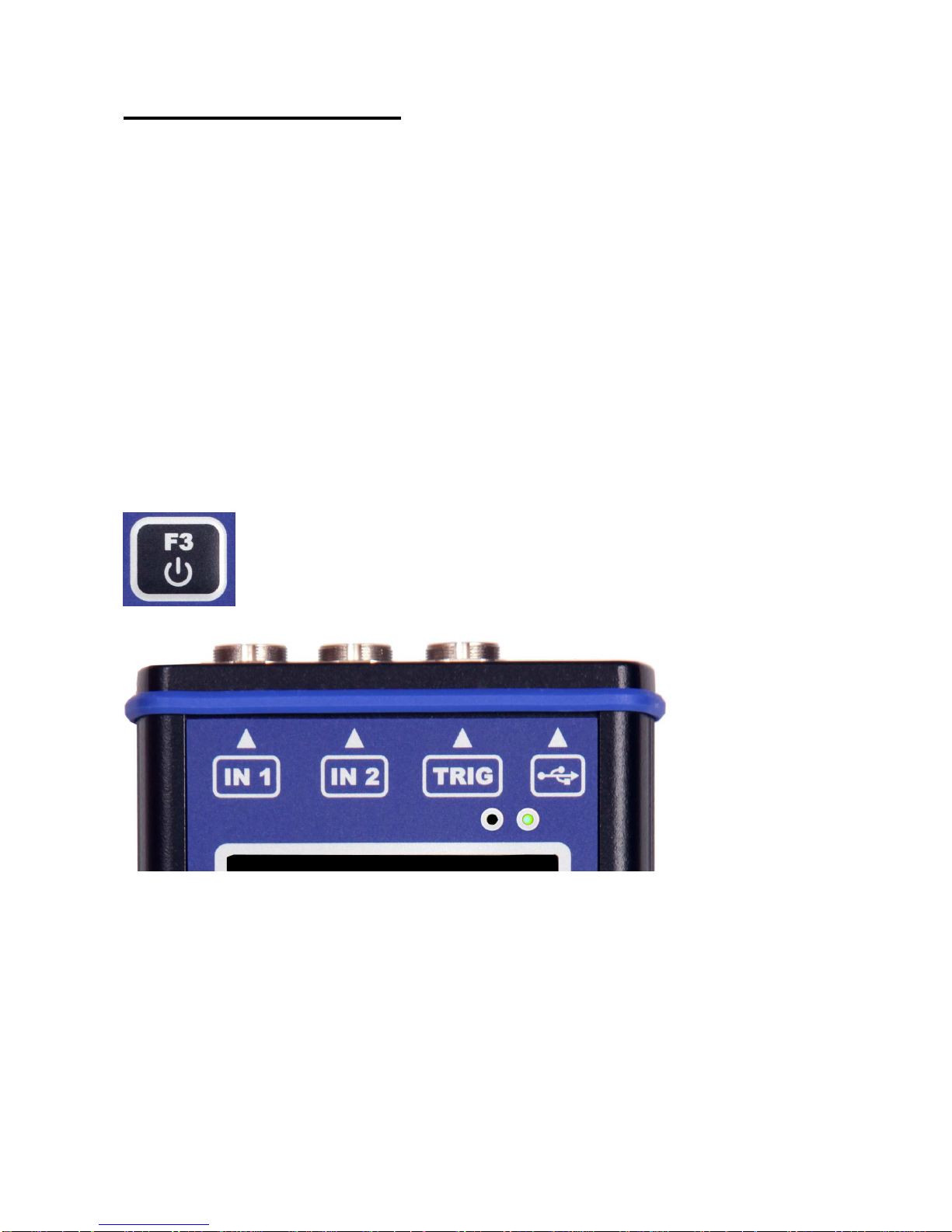
Switching on
Use the POWER button to switch-on the device.
Push and hold the button until the right hand LED on the front panel (top right) changes colour from orange to
green.
Battery
The information about % of battery lifetime is displayed on the top right corner of the display. When the battery
is charged more than 25% the battery symbol is green. When the battery is charged 5-25%, the yellow symbol
is used. Under 5%, the red symbol appears.
Switching off
Switching off can be done on the instrument’s main screen. Press the POWER button and confirm by pressing
Yes.
ADASH Ltd. Adash 4300 – VA3Pro
10
The emergency switch off
This is not the correct method of switching off the instrument. Using it can cause data corruption. Use this
method only in cases when it is absolutely necessary.
Push and hold the POWER button for about 5 seconds, then release the button. The instrument will switch off.
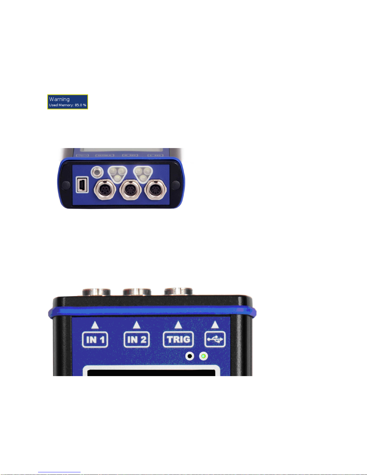
Memory capacity warning
If the memory capacity warning appears (see the picture below), you need to free up some memory space by
removing some measurements or routes.
Connection to the computer
Use the mini-USB cable, which is the standard accessory of the VA3Pro set, to connect the device to the
computer. There is a mini-USB port on the top side of the VA3 device for the connection.
The VA3Pro unit should be switched off or on the main menu screen.
When the VA3 is connected, the new device (new flash drive) appears on the computer. The name is
VA3_DISC. If this operation fails, switch off the unit and try to connect it again.
Always use the Safely remove hardware function before disconnecting the VA3Pro unit from the PC!
The va3 folder (case sensitive) is automatically created on VA3_DISC.
The DSP board
The DSP board is the most important part of the instrument. The special chip carries out all necessary
operations which are required for achieving 3 channel synchronous data measurement.
The DSP status LED is the right hand LED on the top right corner and allows the operator to monitor the DSP
board. Several states can appear:
- Flashing green with 0.25 sec time interval (4Hz, four times per sec) - the measurement is running.
- Flashing green with 1 sec time interval - STANDBY, the measurement is not running.
- Red - the DSP board is not working properly.

ADASH Ltd. Adash 4300 – VA3Pro
11
The CPU status LED
The CPU board contains the CPU chip.
The CPU status LED is the left hand LED on the top right corner and allows the operator to monitor the CPU. If
this LED blinks (like a heart beat) the CPU is working properly.
Virtual Analyzers Data Processing
Many analyzers take multiple readings step by step. This means that when the user wants to get for example
acceleration overall, velocity overall, velocity time signal and velocity spectrum from one sensor, then the
analyzers take the overall first, then the second overall with the integration, after that the time signal and finally
the spectrum. The time which is required for all 4 readings is the sum of all 4 individual times.
The VA3Pro instrument includes high speed chips and it uses a much more advanced concept. There is one
virtual analyzer created in the instrument memory for every individual reading. All virtual analyzers read the data
from the input DSP board and perform the required data acquisition at the same time.
What does this mean? It means that the total required time is not equal to the sum of all individual times, but it is
equal to the time required for the longest reading.
ADASH Ltd. Adash 4300 – VA3Pro
12
How to work with the Menu
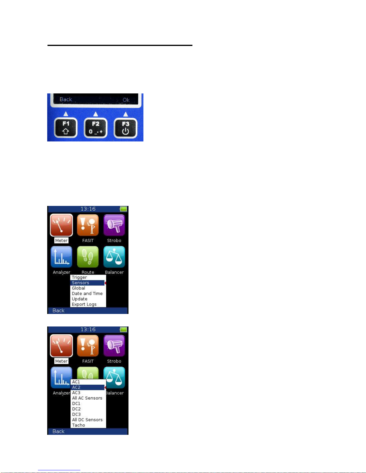
Special buttons
The F1, F2 and F3 buttons are on the top of the keyboard. These buttons have various functions depending on
the actual running process.
The description of their functions is displayed at the bottom of the screen, directly above them.
Example: F1 means Back and F3 means OK.
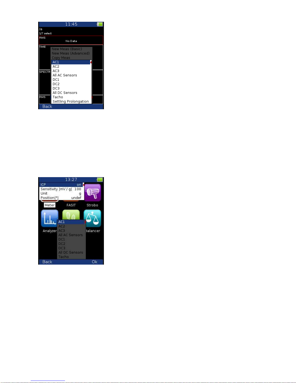
Item selection
Before taking the readings you have to define several parameters. They can be set in the Menu Item. The
operation procedure is the same for all menu items. We will describe it with an example - the sensor properties
definition.
Press the Menu (F2) on the main screen.
Select the Sensors item and press OK. The sensors properties menu appears.

ADASH Ltd. Adash 4300 – VA3Pro
13
Use the arrow buttons for the item selection, e.g. AC2. Then press the OK button. The second menu appears.
Use the arrow buttons for the item selection again. Then press the right arrow button to display possible
parameters of the selected item. E.g. for Sensitivity you see this picture:
User defined values
Use the arrow button for sensitivity selection (1,10,100). In most cases you would want to enter the user
sensitivity according to the real sensor sensitivity of your sensor (e.g. 96,8 mV/g). Select the user and press
OK. The next window appears and the buttons gets the numerical values entry functions. If you need to Delete
value or BackSpace use the button F1 and then press the button 7 or 9.
Use the buttons and enter required value (e.g.45). If you need to edit the value, press the F1 button. F1
changes the functions of buttons.
Now you can move the cursor, to use the Delete function. Press F1 again and the buttons functions change
back. When the value is correct, press OK. The menu with new value appears.
ADASH Ltd. Adash 4300 – VA3Pro
14
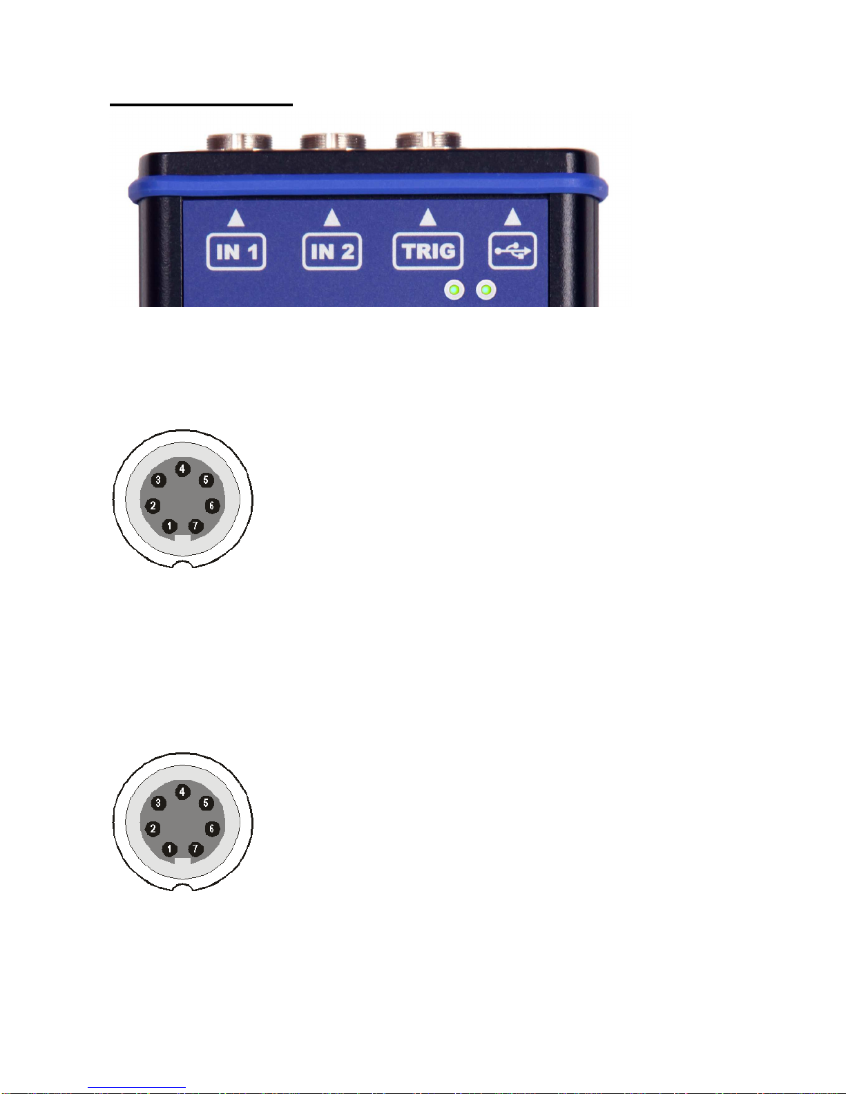
Input channels
The inputs labeled IN1, IN2 are used for AC/DC signals. The input labeled TRIG is used for trigger signals,
usually tacho (speed probe). All inputs have several pins. IN2 allows the user to connect a tri-axial sensor.
The AC inputs allow the measurement of a maximum voltage peak of +/-12V. The DC inputs allow the
measurement of a maximum voltage peak of +/-24V.
IN1 input
1 – CH1 AC/DC INPUT
2 – GROUND
3 – NOT USED
4 – SHIELDING
5 – NOT USED
6 – NOT USED
7 – NOT USED
IN2 input
1 – CH2 AC/DC INPUT
2 – GROUND
3 – CH1 AC/DC INPUT
4 – SHIELDING
5 – CH3 AC/DC INPUT
6 – NOT USED
7 – NOT USED

ADASH Ltd. Adash 4300 – VA3Pro
15
TRIG input
1 – GROUND
2 – GROUND
3 – GROUND
4 – +5 V OUTPUT / 100mA for the tacho power supply
5 – TRIG INPUT - for tacho signal
Standard cable specifications
Sensor signal – pin number 1
Ground – pin number 2
When you use the standard cable:
In the IN1 socket - the signal is measured on CH1.
In the IN2 socket - the signal is measured on CH2.
If you want to use the tri-axial sensor, then you should use the IN2 socket (pins 3,1,5) + ground (pin 2). You
need a special cable for this purpose.

ADASH Ltd. Adash 4300 – VA3Pro
16
Main menu
Select the Menu (F2) on the main screen. The main menu appears.
Trigger
Select the Trigger item and press OK.
Trigger Mode
single Only one reading is taken and displayed.
retrig When you use the analogue oscilloscope, you always see the current signal on the
screen. The retrig mode means a similar thing. The reading repeats until you press the Stop button. Select the
single option when you only want one reading.
Runup Mode
Defines how often the data will be taken in the runup mode.
asap The next measurement is taken immediately after previous measurement without any
delay.
manual The user starts next measurement manually.
speed The next measurement is taken when the speed is significantly different from the
previous measurement speed. The user defines in Speed change item, what it is significant change.
time All measurement are taken with the same time interval between them. The time interval
length is defined in Time Change.
time or speed This option is the combination of speed and time. The next measurement is taken when
one of them is changed more then the value Speed change or Time Change.
Speed change see Runup Mode: speed (the previous section).

ADASH Ltd. Adash 4300 – VA3Pro
17
Time change(s) see Runup Mode: time (the previous section)
Trigger Source:
freerun The measurement process begins immediately (after pressing the Start button -
Analyzer mode).
external The measurement process begins, when the external signal (voltage level higher than
defined in External Trig Level) appears on the trigger input. Such a signal may be generated when the machine
starts to work, for example. This type of signal is usually created in the control system.
manual The measurement process begins after pressing the Start button and then the OK
button. The first press (Start) is for preparation, the second (OK) is for triggering.
manual sequential Similar to manual but every reading for averaging must be started separately.
E.g. when AVG=10, then the OK button must be used 10 times.
amplitude The measurement process begins when the signal level exceeds the Ampl Trig Level,
which is also set by the user in this menu. Both positive (rising edge) and negative (falling edge) levels are
accepted. E.g entering 5g will trigger on 5g. The signal amplitude is taken directly from the sensor input, no
additional filtering is applied.
Examples:
the level is set to 100mV - triggered when the rising signal goes from e.g.99mV to 101mV
the level is set to -100mV - triggered when the falling signal goes from e.g.-99mV to -101mV
tacho The tacho is a special type of external trigger. When we say tacho, we mean a signal
(usually a TTL) which contains one pulse during one rotation of the shaft. It can also be understood as a series
of single external pulses. The measurement process begins when the external signal (a voltage level higher
than the Tacho Trig Level defined in tacho sensor) appears on the trigger input (the same as an external
item). Speed measurement, time signal averaging, aps and order analysis are only enabled when the tacho is
set.
Pretrig (%) value in (100,-100) or user Usually the measurement process (e.g. time signal) begins
exactly from the trigger moment. But in some applications you are also interested in knowing the signal before
the trigger. The required time should be defined in seconds, but in signal analyzers it is usually defined as
percentage part of the total signal length. When a 1 second time signal is measured and pretrigger=25, then
0,25s will be taken before the trigger and 0,75s after the trigger. Also a negative pretrigger could be used. It
means that the time signal will be taken later then the trigger pulse.
Ampl Trig Level (unit) value See the description of the amplitude mode (Trigger Source
section). The unit is the unit of the sensor on the selected channel (Ampl Trig Channel).
Ampl Trig Channel ( 1,2,3) The number of channels, which will be used for amplitude triggering.
External Trig Edge rising, falling The edge used for triggering
External Trig Level[V] See the description in Trigger Source/ external
Sensors
When you connect the sensors to the instrument, you have to specify what kind of sensors you are using. The
Sensors button is displayed on most of the screens and once it is there, it is on the bottom.
Push the Menu on the main screen and select Sensors. Push the OK button. In the next menu select the
channel sensor you want to define.
ADASH Ltd. Adash 4300 – VA3Pro
18
AC1 – AC3 setting of each AC channel properties
All AC Sensors setting of all AC channels together
DC1 – DC3 setting of each DC channel properties
All DC sensors setting of all DC channels
Tacho setting of tacho channel properties
Settling Prolongation if you need longer time for sensor settling, use this item
AC sensors
AC (alternate current) sensors are used for signals, e.g. vibrations.
ICP on, off (selection of required setting accordingly to the sensor type)
Sensitivity[mV/unit] usually 1,10,100, user
Unit the unit selected from the list or the user unit
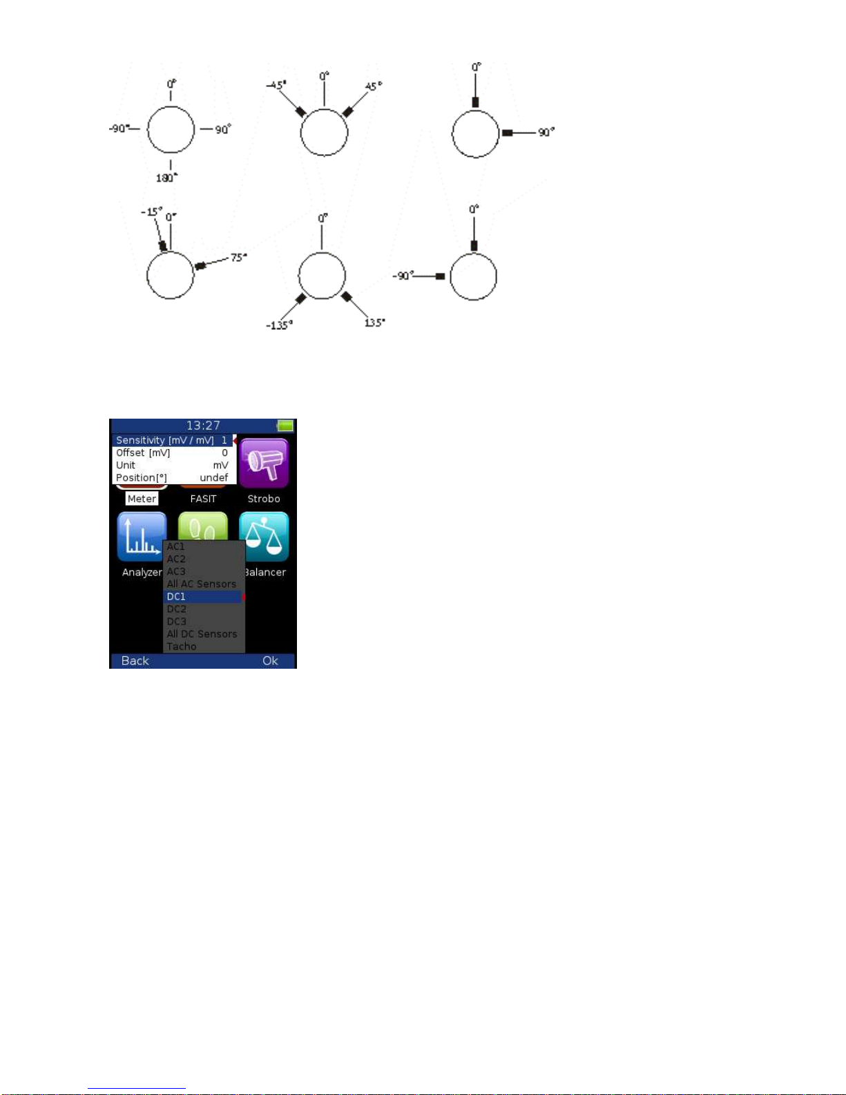
Position the angle of the sensor (see picture bellow). Usually used for proximity sensors.
ADASH Ltd. Adash 4300 – VA3Pro
19
DC sensors
DC sensors are used for discrete current signals, e.g. temperature, pressure, etc .
After selection of DC1 – DC3 or All DC Channels item the sensor properties menu appears.
Sensitivity[mV/unit] sensitivity value
Offset[mV] offset value
Unit the unit selected from the list or the user unit
Position the angle of sensor (see picture above). Usually used for proximity sensors and GAP
measurement.
The used formula: output value in Unit = (input value in mV - Offset) / Sensitivity.
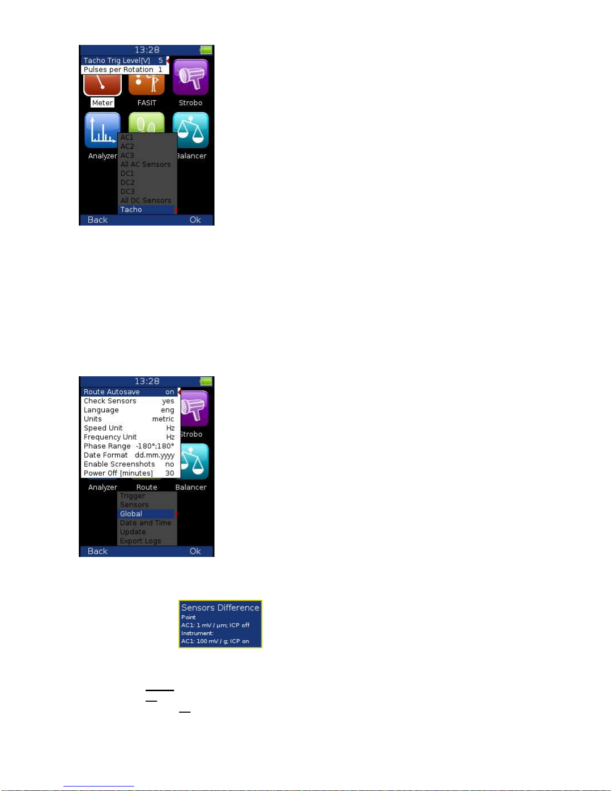
Tacho
The speed is measured from the tacho channel. The signal contains one or more pulses per one rotation. The
pulses can also trigger the measurement.
ADASH Ltd. Adash 4300 – VA3Pro
20
Tacho Trig Level The correct reference value has to be set for speed measurement. E.g. when the
standard tacho level is 0.5V and the pulses reach the 1.5V, then the value 1V should be correct. The negative
pulses are not allowed, you need to use the Adash converter for them.
Pulses per rotation This value has to be set for correct speed evaluation, when more pulses are generated
during one rotation. The Trigger Source=tacho is not available for more then one pulse.
Global
The parameters which have effect on all or many functions are understood as Global parameters.
Press the Menu on the main screen and select Global. Press the OK button.
Route Autosave off, on automatically saves the data after reading is taken (in route mode)
Check Sensors yes, nochecks the difference of sensor settings (point in route vs. instrument) when the
point (or set) is opened,
if the difference is found the warning window appears
Push the Ignore button (F1) to continue without change.
Push the Rewrite button (F3) to rewrite sensor settings in the instrument by the Point.
Language ENG, CZE
Units metric, imperial
Speed unit Hz, RPM, CPS, CPM
Frequency unit Hz, RPM, CPS, CPM
Phase Range -180,180
0, 360
Table of contents
Other Adash Measuring Instrument manuals

Adash
Adash 4900 Vibrio III User manual

Adash
Adash VIBRAMON 1 User manual

Adash
Adash A3716 User manual

Adash
Adash VA5 Pro User manual

Adash
Adash A4900 - Vibrio M User manual

Adash
Adash A3716 User manual

Adash
Adash 4900 Vibrio Ex User manual

Adash
Adash 4300 - VA3 User manual

Adash
Adash 4300 - VA3 User manual

Adash
Adash A4900 - Vibrio M User manual


Popular Measuring Instrument manuals by other brands


Thermo Scientific
Thermo Scientific Antaris II manual

truflo
truflo TIB Series instruction manual

Hioki
Hioki HiTester 3443-01 instruction manual

Litre Meter
Litre Meter VFF Series Installation, operating and maintenance instructions

HT Italia
HT Italia IMP57 user manual

Mitsubishi Electric
Mitsubishi Electric MELSEC iQ-R Series Introduction Guide


