Adash 4900 Vibrio Ex User manual

Adash 4900 - Vibrio M
Version 4.00 and later
Machine vibration diagnostics
Bearing diagnostics
Lubrication diagnostics
Route measurements (4MB memory)
Service activities
Product Inspection
Ex version available
Wideband RMS or PEAK measurements of acceleration, velocity and displacement
Velocity measurement from 10Hz, optionally from 1 Hz for low speed machines
Time signals measurement
Spectrum FFT analysis
Measurement in frequency bands for bearing diagnostics
Store data and perform route measurements
Built-in ISO 10816 limits
Fault Source Identification and Diagnostics Tool
Headphones for "listening of vibration"
Built-in Infrared Thermometer
Built-in stroboscope lamp
Built-in torch
Detection of machine and bearing conditions
Detection of machine speed
Colour OLED graphic display
External piezoelectric accelerometer with 100 mV/g sensitivity
Overload indicator, sensor fault and cable fault indicators
Simple control by three buttons
Ver.: 2206_2015
User’s Guide

ADASH Ltd. Adash 4900 – Vibrio M
Further technical and contact information can be found at www.adash.com
2
Contents
Why perform vibration diagnostics.................................................................................... 5
Why A4900 - Vibrio M?........................................................................................................ 6
The instrument memory...................................................................................................... 7
Two instrument versions................................................................................................... 7
Upgrade to advanced version........................................................................................... 7
Off-Route measurement ................................................................................................... 7
Route measurements........................................................................................................ 7
Vibration Diagnostics - Basic Information......................................................................... 8
Introduction....................................................................................................................... 8
Basic Rules....................................................................................................................... 8
Machine and bearing condition diagnostics....................................................................... 9
Methods for ball bearing condition diagnostics.................................................................. 9
The relation between gears and ball bearings................................................................... 9
Fault Source Identification and Diagnostics Tool..............................................................10
Measurement Points........................................................................................................10
The preparation of the measurement point ......................................................................11
Listening to Vibrations Using Headphones.......................................................................12
Relationship of Measuring in Acceleration and Speed .....................................................12
Abbreviations used in the guide.......................................................................................12
What Will You Get with Your Instrument..........................................................................13
Instrument and accessories.............................................................................................13
Before You Start.................................................................................................................14
Standards for vibration measurements............................................................................15
Adash Limit Values of Machine and Bearing Vibrations...................................................16
ISO 10816 limit values.....................................................................................................17
Classification according to machine type, nominal power or shaft height..................................17
ISO Groups 1-4 classifications define the following types of machinery:...................................17
Classification according to foundation........................................................................................ 17
Evaluation ranges....................................................................................................................... 17
Classification of vibration values for machines groups 1 and 3 ................................................. 18
Classification of vibration values for machines groups 2 and 4 ................................................. 18
Values setting in A4900 - Vibrio M unit.............................................................................18
Quick Start..........................................................................................................................19
Preparation of Measurement Point...................................................................................19
Putting in Batteries...........................................................................................................19
Plugging in Vibration Sensor............................................................................................20
Connectors - top panel.....................................................................................................21
Vibration Measurements..................................................................................................22
Temperature measurement..............................................................................................22
Automatic detection of the machine speed.......................................................................23
Evaluation of the machine and bearing conditions...........................................................23
Fault Source Identification and Diagnostics Tool..............................................................23
The Stroboscope .............................................................................................................24
The Torch........................................................................................................................24
Using of headphones.......................................................................................................25
Instrument Operation.........................................................................................................26
Switching on and off.........................................................................................................26
Stand by mode.................................................................................................................27
Information line................................................................................................................27

ADASH Ltd. Adash 4900 – Vibrio M
Further technical and contact information can be found at www.adash.com
3
Selection of Measurement ...............................................................................................28
Measurement Methods Screens ......................................................................................28
Speed detection and definition.........................................................................................32
MENU for functions selection...........................................................................................33
LIGHT - TORCH......................................................................................................................... 34
LIGHT - STROBO....................................................................................................................... 34
MEMORY.................................................................................................................................... 35
ROUTE ....................................................................................................................................... 35
VIEW........................................................................................................................................... 35
CLRDATA................................................................................................................................... 35
MEMORY – CLR ALL................................................................................................................. 35
VOLUME..................................................................................................................................... 36
SETUP........................................................................................................................................ 37
SPEED........................................................................................................................................ 37
ALARMS..................................................................................................................................... 38
MEASURE.................................................................................................................................. 38
MEASURE - UNITS.................................................................................................................... 38
MEASURE - DISPLACEMENT VALUE...................................................................................... 39
TIME SETTING........................................................................................................................... 39
-ESC-.......................................................................................................................................... 39
Error Messages ...............................................................................................................40
Sensor connection Error............................................................................................................. 40
Display Value Overload.............................................................................................................. 40
Input Overload Error................................................................................................................... 40
Measurement Error..................................................................................................................... 41
Using the memory..............................................................................................................42
Off-Route measurements.................................................................................................42
Measurement screen No.1 properties........................................................................................ 43
Measurement screen No.2 properties........................................................................................ 43
Measurement screen No.3 properties........................................................................................ 44
Measurement screen No.4 properties........................................................................................ 44
Measurement screen No.5 properties........................................................................................ 44
Measurement screen No.6 properties........................................................................................ 45
Measurement screen No.7 FASIT properties............................................................................. 45
Measurement screen No.8 properties........................................................................................ 45
Route measurements.......................................................................................................46
Readings..................................................................................................................................... 48
How to evaluate the failure................................................................................................50
Overall RMS values.........................................................................................................50
Overall PEAK values........................................................................................................51
Spectrum 200 Hz– Detection of Looseness....................................................................51
Time signal for bearing condition evaluation....................................................................52
Vibrations in frequency bands – gearboxes/bearings.......................................................54
Fault Source Identification and Diagnostics .....................................................................55
Adash 4900 – Vibrio M Specifications ..............................................................................56
Response specification....................................................................................................57
Calibration .......................................................................................................................57
Vibration velocity measurement frequency response.......................................................57
Vibration acceleration measurement frequency response................................................57
Velocity measurement amplitude response......................................................................58
Acceleration measurement amplitude response...............................................................58
Sensor sensitivity.............................................................................................................58
Basic test with A4801 Sensor Simulator...........................................................................58
Basic test with sensor and shaker....................................................................................58
Advanced tests of velocity measurement.........................................................................58

ADASH Ltd. Adash 4900 – Vibrio M
Further technical and contact information can be found at www.adash.com
4
Advanced tests of acceleration measurement..................................................................59
Envelope demodulation test.............................................................................................59
Adash 4900 - Vibrio Ex - The ATEX Appendix (option)................................................60
Specification according to 94/9/EC (ATEX) directive:.......................................................60
Zones categories.............................................................................................................60
Using of Instrument..........................................................................................................60
Certificated accessories...................................................................................................61
Accelerometer AC90x................................................................................................................. 61
Baterie......................................................................................................................................... 61
Headphones ............................................................................................................................... 61
The unit sticker ................................................................................................................62
Adash 4900 - Vibrio MP (proximity option).......................................................................63
Switch On of Instrument...................................................................................................63
Screens ...........................................................................................................................64
Speed enter ................................................................................................................................ 64
DC offset..................................................................................................................................... 64
Displacement in 1-1000Hz range............................................................................................... 64
Spectrum 1000Hz or 2500Hz ..................................................................................................... 65
Spectrum 200Hz......................................................................................................................... 65
Time waveform in 1-1000Hz.......................................................................................................65
Setup...............................................................................................................................66
RevCnt........................................................................................................................................ 66
CONFIG...................................................................................................................................... 66
EVAL........................................................................................................................................... 66
SENSOR..................................................................................................................................... 67

ADASH Ltd. Adash 4900 – Vibrio M
Further technical and contact information can be found at www.adash.com
5
Why perform vibration diagnostics
Vibration diagnostic allows checking the condition of all your machinery. You will be informed early
about potential failure before the machine gets damaged and you will be able to order only real
specific required maintenance (instead of expensive overhauls). The periodical measurements will
allow you to keep your machines in good health.

ADASH Ltd. Adash 4900 – Vibrio M
Further technical and contact information can be found at www.adash.com
6
Why A4900 - Vibrio M?
You always ask before you make a decision to buy the new instruments what unit is the best for your
needs. Is it an instrument with a large amount of functions, including specialized software for data
processing (which you will not ever use), or is it an instrument which is easier to use and contains all
required functions? You should pay only for functions, which you will use in the field. The A4900 is just
that instrument. The instrument uses standard external accelerometer with the magnetic base. It
enables correct repeatable measurements. You should not equate our unit with "vibration pens".
The Adash model A4900 is a multi-function portable meter and data-collector that bridges the gap
between the basic and advanced FFT data-collector/analyser. It is a complete machine condition
expert system than gives results without the use of a computer or lap top. It is designed for the field
maintenance persons, technician, engineer and consultant who need to analyse a rotating machine
on-site without investing and carrying expensive instruments to site.
This single meter can measure overall vibration measurement, band graph, 800 lines spectrum, 2048
samples time signals, temperature, rotation speed, strobe scope. In addition it incorporates a strobe
scope, handy inspection torch and stethoscope.
The A4900 caters to ISO 10816-3 with expert rules covering machine health vibration levels, that
identify the prime machinery faults: Unbalance, Looseness and Misalignment. An anti-friction bearing
health level indication is also incorporated. Many informative screens are available.
Do your machines work under optimum conditions?
The A4900 will:
- Determines the condition of your bearings, including slow-running ones.
- Identify insufficiently lubricated bearings.
- Indicates unbalance, looseness, misalignment.
- Check machine speed by built-in stroboscope.
- Check machine temperature by non-contact temperature meter.
- Measures in either Metric or English units.
Operation of A4900 is easy to use. Colours green, orange and red display the status. Determination of
individual machine or bearings defect types is done directly during operation, without need of use a
computer or software. Despite the A4900 is very compact and rugged, it is designed and fits in the
palm of a small hand. Nevertheless the A4900 is big in performance.
The A4900 is supplied complete set with an accelerometer, coiled cable, magnetic base, transit case
and headphones. You can connect headphones to listen to machinery noise related to vibration and
process. When measuring transmissions or slow-running bearings, you will quickly appreciate the
benefits of the headphone accessory.

ADASH Ltd. Adash 4900 – Vibrio M
Further technical and contact information can be found at www.adash.com
7
The instrument memory
The model A4900 - Vibrio M has got 4MB data memory.
Two instrument versions
You can buy two versions of this device. The basic version (cheaper) has not available the memory.
The advanced version can use the memory. Both of them has the memory installed on the board and
only the firmware is different.
Upgrade to advanced version
If you want to upgrade the basic version to advanced version, ask your supplier for it. He can rewrite
the firmware in the device.
Off-Route measurement
The instrument offers many kinds of measurement. The results are displayed on specific screens.
Some screens contain more results ( e.g. RMS and Peak), some screens contain only one (e.g.
spectrum). You can save each screen to the memory. Such data are labelled as OFF-ROUTE.
Route measurements
The list of required measurements you can prepare in computer, actually in DDS2014 software. You
load the list to the A4900 - Vibrio M instrument. Then the standard route arrangement is available. You
see the name of sensor location on the screen, mount the sensor to that point and take the
measurement. Such data are labelled as ROUTE data. You download them back to the computer and
use the software for next data acquisition.

ADASH Ltd. Adash 4900 – Vibrio M
Further technical and contact information can be found at www.adash.com
8
Vibration Diagnostics - Basic Information
Introduction
What is it the vibration diagnostics? This chapter explains the basic steps and you will be able to begin
practical measurements. More information you can find in the literature.
When we are talking about the vibration diagnostics, we mean regular measurements (usually
every 2-4 weeks), whose objectives primarily are:
1. Finding of change of vibration level, it means change of machine operational condition.
2. Determining reason of this change.
3. Recommending maintenance (repair, adjustment, lubrication etc.).
4. Checking of maintenance success (including revision of dismantled part to confirm the
analysis).
The machine vibration diagnostics solves two basic tasks:
1. Diagnostics of machine mechanical failure (imbalance, misalignment, mechanical
looseness etc.).
2. Diagnostics of rolling bearing condition.
Basic Rules
1. If the measured value of vibration increases in time, it is a change indicator - worsening of
the machine condition.
2. If the measured values do not change, the machine works in stable operation condition.
This doesn’t necessarily mean good condition. For example if a bearing was installed incorrectly, then
there will be high signal value immediately. This value will remain stable for some time (the bearing will
be able to withstand it), but then there will be a fast increase and destruction of the bearing. This short
bearing life can take hours, days, weeks or even months.
3. Reliability of the diagnostics will never be 100%.
There will always be defects, which develop in time shorter than regular measurements. The defects
caused by material fatigue can develop in several seconds only (cracks, breaks). The proof of the
diagnostic performance is primarily a decrease in maintenance costs (not to absolute zero) and a
significant decrease in unexpected breakdowns (not their complete elimination).
4. Using of standards is possible only with special machines, for which the special standards
exist.
It is not possible to simply define limit vibration values in general for a wide range of machines.
However, it is possible to create the standards for special machines (e.g. turbines), and these
standards are a strong diagnostic tool. General standards have a character of recommendation on
how to define the limit values. The way how to find the good condition values is to use measured
values of new or repaired machine. Also you can ask the machine producer for them.
5. Shortening of an interval between measurements means more successful prevention of
unexpected failures.

ADASH Ltd. Adash 4900 – Vibrio M
Further technical and contact information can be found at www.adash.com
9
Machine and bearing condition diagnostics
Basic defects which we’d like to find out are
- unbalance (heavy spot on the rotor causes vibrations),
- misalignment (machinery parts are not in alignment ),
- looseness (machine is not properly connected with its base - soft foot),
- bearing defect (wear of bearing, bad assembly, bad lubrication or overload).
First three defects influence the whole machine (e.g. the vibration caused by unbalance we can take
from any point on the machine). We use the vibration velocity [mm/s] measurements for that.
Roller (ball) bearing condition we can detect only on the nearest point. This is the local failure. We
measure always vibration acceleration only [g].
Methods for ball bearing condition diagnostics
We can find out several methods for bearing condition detection in literature. We should repeat again:
We have to measure vibration acceleration in [g]
for correct data acquisition. All methods must satisfy the conditions.
We can choose different procedures for evaluation of the acceleration signal. Measured signal can be
imagined as a level of the river. It flows with appropriate speed and there are little or big waves. If we
want to measure the stream we can measure the flow per hour or prompt wave's level. The value of
the flow will be stable and it will change slowly. But the wave's levels are unstable because
measurements have significant variety of values.
The similar effects occur for bearing condition measurements. You can measure RMS value (the total
energy in signal) or PEAK value (the highest peak in signal). We can use both types for evaluation,
just have to realize of advantages and disadvantages.
RMS measurement
- advantages - stable and well repeatable, time trends are well readable
- disadvantages - if wear increases the response is slower then PEAK, but sufficient for
maintenance.
PEAK measurement
- advantages - fast response for any condition change.
- disadvantages - not stable and well repeatable (extremely sensitive), time trends are not well
readable.
From these two basic measurements further measurements are derived:
- g
ENV
- envelope signal modulation. Advantages and disadvantages are in the middle
of RMS and PEAK measurements.
-g
SE
BCU, SEE, SPM - measurements are performed usually on the sensor resonance frequency.
These methods have the same advantages and disadvantages like the PEAK measurement.
The relation between gears and ball bearings
For gearboxes diagnose it is also necessary to measure acceleration signal like for ball bearings.
When the balls are rolling over the damage tracks (pitting), the shock pulses occur in signal.
Unfortunately similar shocks are also in signal from on worn or damaged gears. So if we measure
gearbox with roller bearings then higher vibration values can be caused by both sources.
More information for this kind of analysis you can find in chapter Vibrations in frequency range -
gearboxes/bearings.
ADASH Ltd. Adash 4900 – Vibrio M
Further technical and contact information can be found at www.adash.com
10
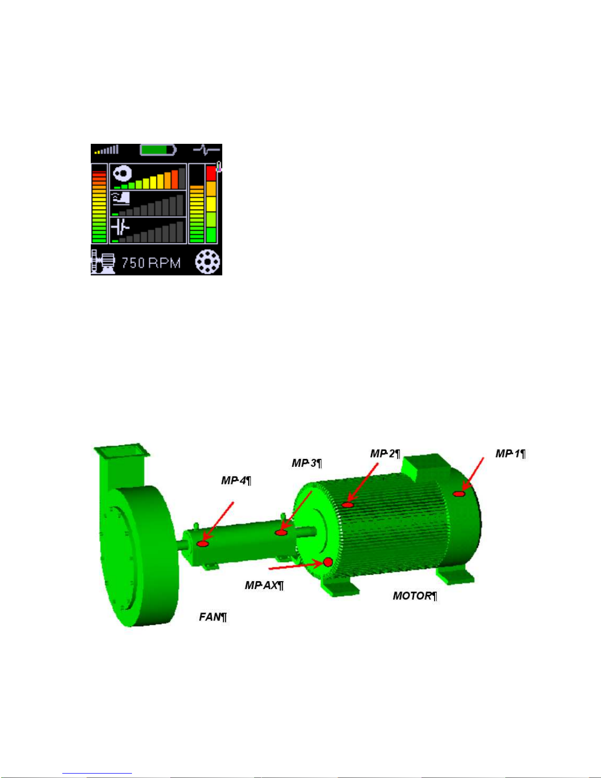
Fault Source Identification and Diagnostics Tool
This tool is included in the Adash 4900 - Vibrio M. It is good message for users, because such function
has never been built in the instrument in this price category. This function display several bar graphs
with traffic light colours. Two major (largest) bars are allocated to general machine condition ( on the
left side) and ball bearing condition (on the right side).
The next three bars are located in the middle. They display the severity level of UNBALANCE,
LOOSENES and MISALIGNMENT (from the top).
Measurement Points
The measurement location must enable repeatable measurements under the same conditions as the
previous measurement. Also the direction of sensor ( radial, axial for rotated machines) is important.
That is why you should determine measurement points on the machine. The typical machine together
with the measurement points on the picture.
For the measurement in radial direction, we are going to place the sensor perpendicularly to the axis
of rotation, for axial measurement along the axis. The radial measurement can be usually performed
horizontally, vertically or in another angle. The importance of the angle choice should not be
overstressed; choose any radial direction with easy access.
ADASH Ltd. Adash 4900 – Vibrio M
Further technical and contact information can be found at www.adash.com
11
The measurement points need to be prepared for the measurements. The best is to place measuring
pads on a machine (see the chapter Preparation of Measuring Location).
The preparation of the measurement point
On the measurement point we make a measurement. To obtain a quality measurement, the points for
measurements must be prepared in advance. For regular measurements the sensor must be always
fixed in the same way at the same point. For diagnostics of bearings it is necessary to fix the sensor
with a magnetic base. Do not push the sensor only by hand - high frequencies cannot be measured in
this way.
The magnetic base is firmly screwed to the sensor and then it is magnetically fixed to the metal
surface of the machine. Hence the sensor is fixed and a measurement is possible. Quality of fixation
markedly influences the result of your measurement. If the sensor swings or jumps about etc., your
measurement is pointless. A layer of paint is also a big obstacle for higher frequencies. The magnetic
base has ground surface and the same surface quality must be created on the machine. In practice, it
is not possible. A flat surface 3x3 cm in size can be ground only in a workshop. Anyway, quality of the
bearing’s housing steel is not high and such a surface can quickly succumb to corrosion. Then it
becomes unusable.
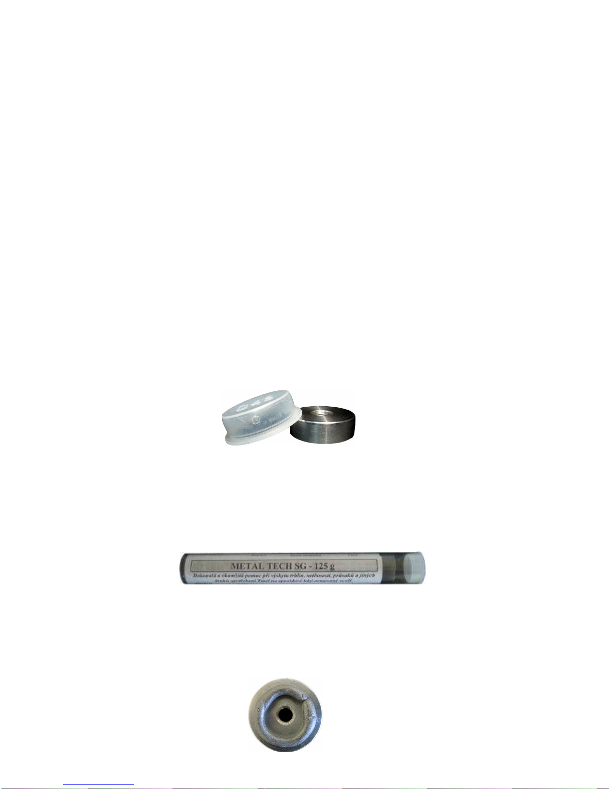
Solution to this problem is to use measurement pads. These are the cylinders with the diameter
approx. 26 mm and height 10 mm with a ground surface, made of a magnetic stainless steel. They are
fixed to chosen points with special glue, which ensures a perfect transmission of the high frequency
vibrations. The pad is covered with a plastic cover, which is removed only for the measurement.
Another advantage of the cover is that when the machine is painted, your measurement point is
preserved. The paint would devalue the pad. It is sufficient to coarsely grind the machine’s surface and
degrease it before the pad is glued. Durability of the pads in time is unlimited. In practice, it is always
until a forcible removal.
You will need mainly the following aids: angle grinder, set of files, sand paper, degreaser (ethanol,
solvent), measurement pads and glue.
Prepare the surface in the following way:
- remove the paint, corrosion or unevenness from the surface by grinding,
- degrease the surface.
The pad is being fixed on measurement point with the glue. We usually use the METAL TECH SG
cement, also other glues with similar properties may be used.
The METAL TECH SG cement is a 2-component epoxy cement with properties best suited for this
task. The two components, after mechanical mixing, chemically react and after drying they form a hard
material resistant to pressure, temperature and humidity.
In the case of the simple pad the procedure is as follows: cut-off a disc approx.3 mm thick from the
cement with a sharp knife. Wet your fingers and work the disc into a homogenous lump. Roll a cylinder
with the diameter approx. 2-3 mm from this lump and put it on the side, which is not roughened.

ADASH Ltd. Adash 4900 – Vibrio M
Further technical and contact information can be found at www.adash.com
12
Push the pad with glue to the prepared place and, while constantly pushing and turning the pad there
and back with circular movements, observe that the cement is being evenly pushed out along the
circumference of the pad. The purpose is to make the layer between the pad and the surface as thin
as possible. ! ATTENTION. CEMENT MUST NOT BE PUSHED OUT COMPLETELY!
Pushed out cement may be removed or levelled out around the pad. In the end you put a cover on the
pad.
When using the Tpad, amount of the cement is dependent on the size of the gap between the motor
ribs and it is not so easy to determine amount of the cement to process. As with the simple pad, the
surface between the ribs must be well cleaned and degreased. The space shall be filled with the
necessary amount of the cement so that only the cylindrical part of the pad remains visible after drying
of the cement. In the end put the cover on the pad.
Listening to Vibrations Using Headphones
A user can connect headphones to the Adash 4900 – Vibrio M instrument, since listening to a
measurement signal also enables a differentiation of a problem type. People can think that this is an
old method, which does not have a place in this modern world. The opposite is true. Analysis of gears
and low speed bearings (e.g. in paper mills) gain better quality by using the listening method. The
listening can easily be done by any maintenance person without deeper knowledge of diagnostics. If
there is a defective bearing, distinct rumbling sound is audible in the headphones then. If the bearing
is OK, then you can hear only a weak noise.
HEADPHONES WARNING !
Listen at moderate volumes to avoid hearing damage.
Always remove the headphones from the ears when you move the sensor or re-connect cable.
Relationship of Measuring in Acceleration and Speed
Maintenance staff usually measure vibrations in mm/s or inch/s (velocity) only and not vibrations in
g = 9.81 m/s
2
(acceleration). This is a relic of the past, when old equipment enabled the vibration
speed measurement only. Bearing defects are not recognizable by using velocity measurements. If the
velocity value increases due to a bearing defect, then the defect is already serious and there is an
acute danger of unexpected breakdown. The measuring of the velocity vibration does not give early
enough warning before failure of a rolling bearing.
For accurate bearing condition measurement you have to measure the acceleration vibration!
Abbreviations used in the guide
Abbreviations below are used in the User’s guide
RPM – Revolutions per minute
CPS – Revolutions per second
RMS – RMS value of the measured signal
PEAK – Peak value of the measured signal
ADASH Ltd. Adash 4900 – Vibrio M
Further technical and contact information can be found at www.adash.com
13
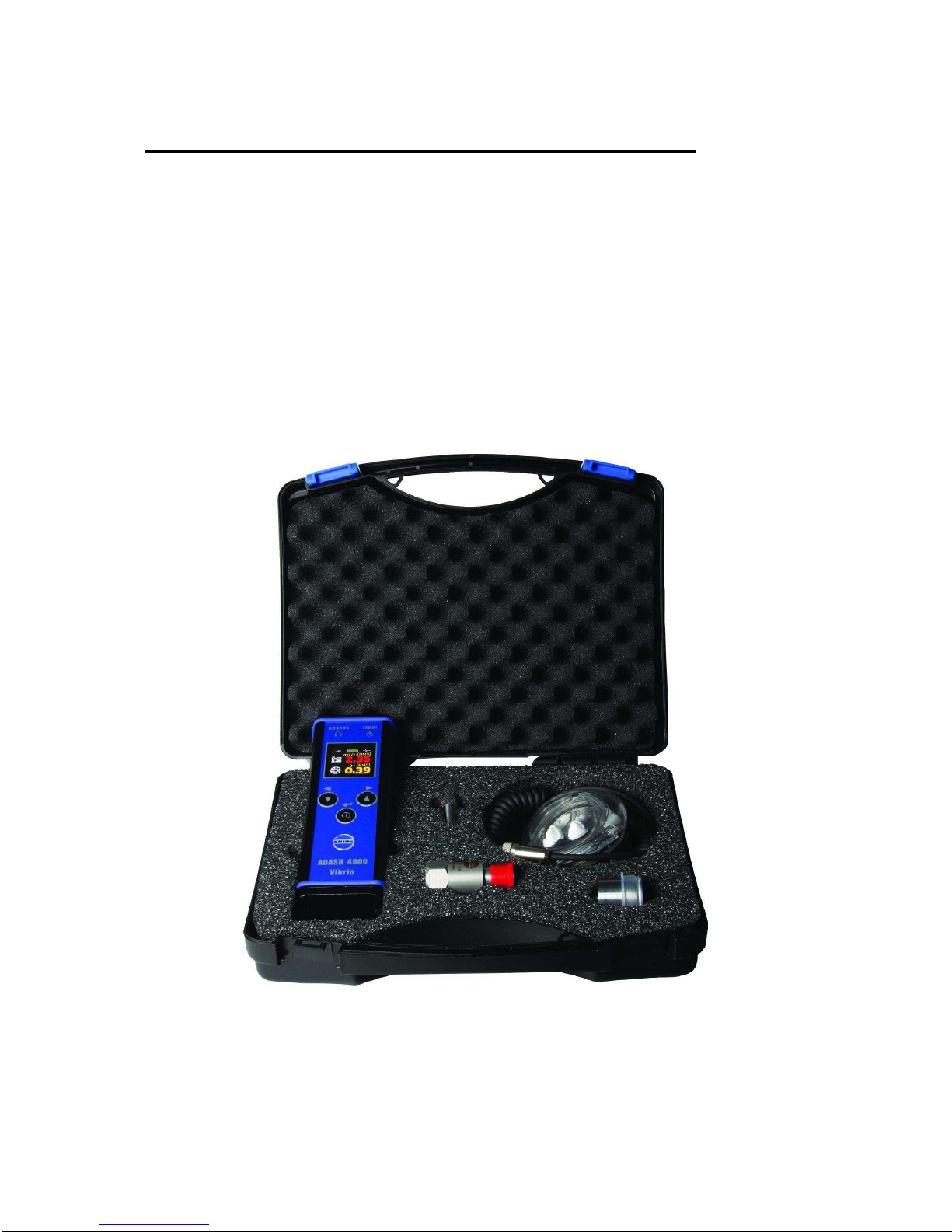
What Will You Get with Your Instrument
Instrument and accessories
The instrument case contains:
- measuring instrument A4900 – Vibrio M
- vibration sensor - accelerometer
- magnetic base for vibration sensor
- coiled cable to connect vibration sensor
- headphones
- measuring tip for putting manual pressure on vibration sensor
- 1.5V alkaline batteries
- CD with the manual
Fig. Adash 4900 – Vibrio M with accessories

ADASH Ltd. Adash 4900 – Vibrio M
Further technical and contact information can be found at www.adash.com
14
Before You Start
1. Always connect only ICP type sensors into an ICP marked socket !
If unsure, consult the procedure with your supplier.
2. Never plug this instrument into 230 V household voltage !
3. To power this instrument, use batteries with max. nominal voltage of 1.5 V!
4. To power this instrument, use only alkaline or rechargeable (NiCd, NiMH) batteries.
Regular carbon-zinc batteries are not suitable.
Ignoring any
of the
recommendations mentioned below may cause failure of the
instrument.
Handling voltage higher then 24 V can cause an accident.
WARNING!
Use correct battery polarity.
Incorrect polarity will cause destruction of the
instrument!
HEADPHONES WARNING!
Listen at moderate volumes to avoid hearing
damage.
Remove the headphones from the ears when
you move the sensor or re-connect cable.

ADASH Ltd. Adash 4900 – Vibrio M
Further technical and contact information can be found at www.adash.com
15
Standards for vibration measurements
Using a standards is occasional topic in vibration diagnostics. Because there are a lot of different
types of machines it is impossible to determine the critical limits of vibrations for wide range of
machines. Its reliability would be low then. It would happen, you will repair machine, which do not
require it. The standards should be rather determined for a narrow range of machines.
A4900 - Vibrio M contains Adash limit values and ISO 10816 limit values. Adash limits are not
rewritten from any existing standard. It’s a result of 20 years of Adash engineering team experiences.
It’s difficult to invent critical value definition which would be simple (that means not many parameters
such as speed, power, bearing type, machine type and so on) and reliable.
On the figures below is clear how we derived limit values. Three levels of machine condition are
defined: GOOD, ALERT (Machines lays in this range are not acceptable for a long period operation,
they could be operated till time when could be repaired) and DANGER (Vibration values in this range
are considered as very dangerous an they can cause a damage of the machine). The corresponding
colours are taken from traffic lights - green, yellow and red.
All limit values are related to the speed value. The low speed machine should generate lower vibration
then higher speed machine.
In the graphs area you found three particular areas. GOOD condition is the space up to the yellow line
that means operation without restriction. The space above yellow but under red line is an ALERT
condition. Possible to operate the machine but have to be more checked. It’s necessary to determine
the source of worse condition and plan repair (for instance change the bearing) or maintenance
(balancing, alignment). The space above red line is an DANGER condition and the machine should
not be operated. First figure contains the values for overall machine condition and you search
unbalance, misalignment, and mechanical looseness above all. They are called “overall” because we
can measure them on most of the measuring points. Second figure contains the limit values of a roller
bearing condition. This condition is local and can be measured only on appropriate bearing house.
Work with figures is simple. It’s necessary to know the speed. Instrument determines it automatically
or user can enter it manually. On the bottom horizontal axis you should find the point which
corresponds with speed. Above this point you will find an intersection with orange and red graph.
Projections to the vertical axis will determine limit values for yellow or red state. If the measured value
is lower than yellow the condition is GOOD – green. If the value is above yellow but under red then the
condition is ALERT – yellow. If the value is higher then red graph then the condition is DANGER – red.
ADASH Ltd. Adash 4900 – Vibrio M
Further technical and contact information can be found at www.adash.com
16
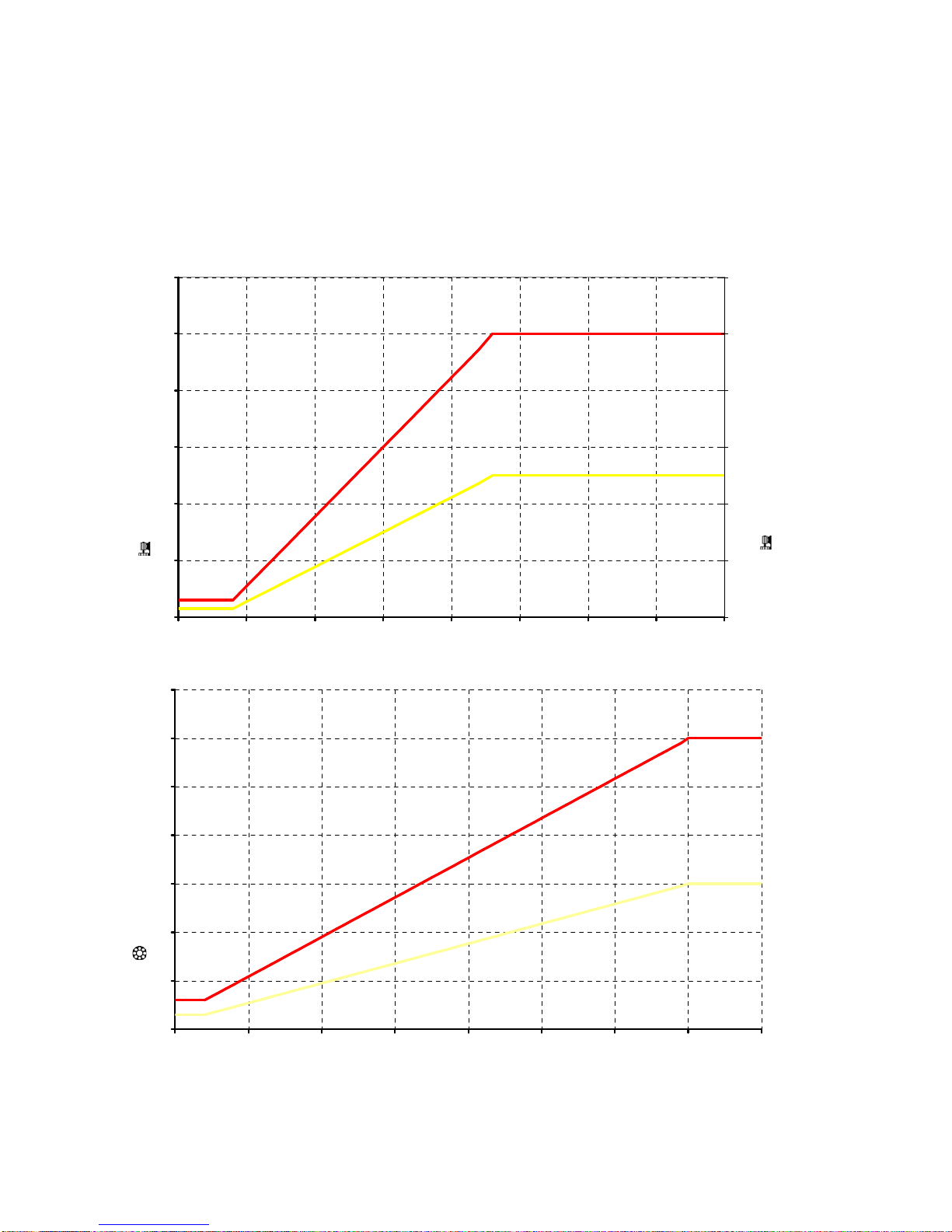
Adash Limit Values of Machine and Bearing Vibrations
Graphs, according to which the instrument determines acceptable vibration limits depending on
machine speed.
0.0
1.0
2.0
3.0
4.0
5.0
6.0
0 500 1000 1500 2000 2500 3000 3500 4000
speed [RPM] ---->
Vel (10-1000Hz) [mm/s RMS] ---->
0
0.04
0.08
0.12
0.16
0.2
0.24
Vel (10-1000Hz) [ips RMS] ---->
0.0
0.5
1.0
1.5
2.0
2.5
3.0
3.5
0 1000 2000 3000 4000 5000 6000 7000 8000
speed [RPM] ---->
Acc (5k-16kHz) [g RMS] ---->

ADASH Ltd. Adash 4900 – Vibrio M
Further technical and contact information can be found at www.adash.com
17
ISO 10816 limit values
There is a wide range of valid standards but we would like to mention ISO 10816. It has several
sections and it also deals with procedures how to gain limit values for particular machines. It contains
3 tables of values, which are applicable for A4900 - Vibrio M unit.
Classification according to machine type, nominal power or shaft height
Therefore, select the Group that best describes the general size, type, and speed of the machinery
being measured. Note that these machine group classifications are set forth in ISO 10816-3, which
rates overall velocity vibration levels for industrial machines with normal power above 15kW and
nominal speeds between 120 r/min and 15000 r/min when measured in situ.
ISO Groups 1-4 classifications define the following types of machinery:
Group 1
Large machines ( rated power above 300kW) with a shaft height greater than 315 mm. These
machines are normally equipped with sleeve bearings.
Group 2
Medium-sized machines (rated power from 15 kW to 300 kW) and electrical machines with a shaft
height between 160 and 315 mm.
These machines are normally equipped with rolling element bearings.
Group 3
Pumps with multi-vane impeller and with separate driver with rated power above 15 kW.
Group 4
Pumps with multi-vane impeller and with integrated driver with rated power above 15 kW.
Classification according to foundation
An additional setting allows the specification (when defining the overall alarm levels) of measurements
taken from machinery with Rigid or Flexible foundations.
Evaluation ranges
For evaluation of the machine health from vibrations there are defined following evaluation ranges.
Range A: New machine vibrations should occasionally be in this range.
Range B: Machines in this range can be operated for unlimited period.
Range C: Machines in this range are not acceptable for a long period operation, they could be
operated till the repair time only.
Range D: Vibration values in this range are considered as very dangerous an they can cause a
damage of the machine.

ADASH Ltd. Adash 4900 – Vibrio M
Further technical and contact information can be found at www.adash.com
18
Classification of vibration values for machines groups 1 and 3
Foundation class RMS velocity values border zone
mm/s in/s
Rigid (R13) 2,3 0,09 A/B
4,5 0,18 B/C
7,1 0,28 C/D
Flexible (F13) 3,5 0,14 A/B
7,1 0,28 B/C
11,0 0,43 C/D
Classification of vibration values for machines groups 2 and 4
Foundation class RMS velocity values border zone
mm/s in/s
Rigid (R24) 1,4 0,06 A/B
2,8 0,11 B/C
4,5 0,18 C/D
Flexible (F24) 2,3 0,09 A/B
4,5 0,18 B/C
7,1 0,28 C/D
Values setting in A4900 - Vibrio M unit
It’s possible to set up these values directly in the unit. Then the measured values are displayed in
traffic light colours. You can choose Adash limits (recommended) or 10-816 limits. Setting up is in
menu under the mode SETUP (see instrument operation).
Coloured marks according to 10-816 are ranges A and B, displayed by green colour. Range C is
yellow and range D is red. It’s necessary to choose a type of evaluation R13, F13, R24 or F24 (see
table above).
ADASH Ltd. Adash 4900 – Vibrio M
Further technical and contact information can be found at www.adash.com
19
Quick Start
The aim of this chapter is to introduce you this instrument, and, without reading a complete User’s
Guide, enable you to measure first vibration values. This chapter does not describe full and detailed
operation of this instrument or measurement methodology. Special chapters in this Guide are intended
for this purpose.
Preparation of Measurement Point
We have to select a measurement point before the measurement itself. We want to choose it in such
way that transmission of vibrations would not be attenuated. Usually this means as close to the source
of vibrations as possible (for instance at a bearing housing). We always have to measure at solid, firm
part of a machine. We should not be measuring on covers and so on. The place should be clean,
without corrosion and paint. It should also be flat so a sensor would not “wobble”. The best is to use a
measurement base, which is glued on a machine. It has a perfect surface, plastic cover, and is made
from magnetic stainless steel. This will enable you to perform the measurements on the machine at
any time under the same conditions. Measurement repeatability means that you will be able to
compare values well.
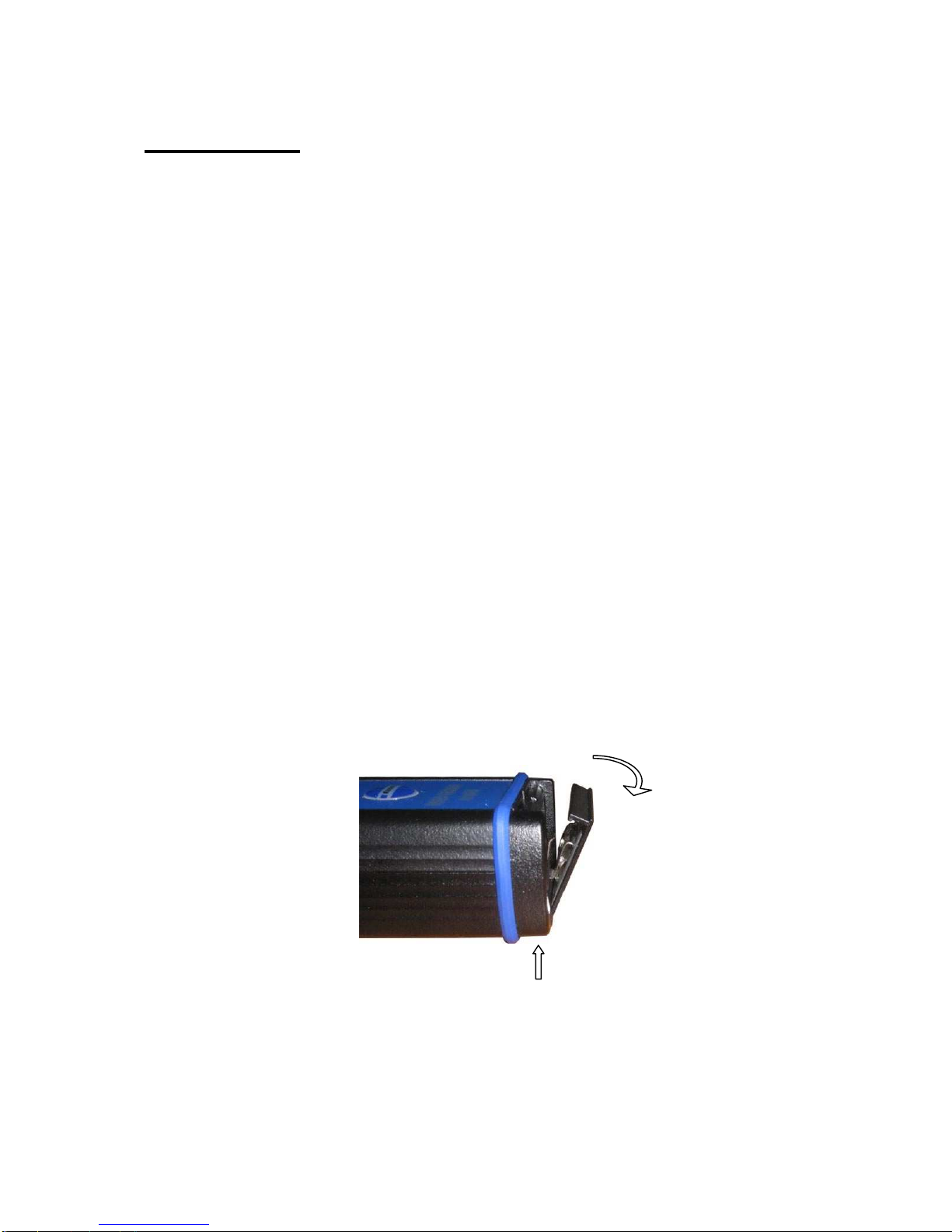
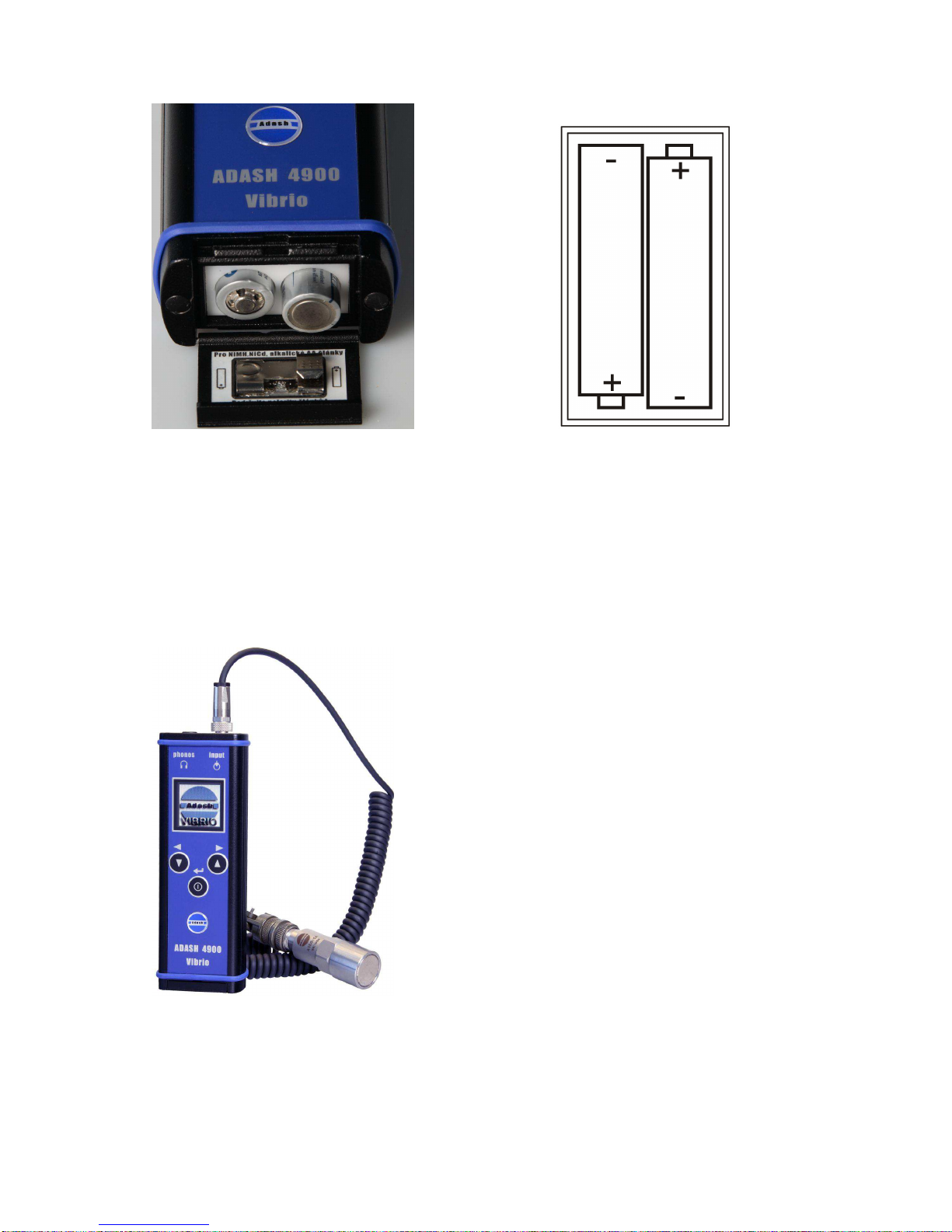
Putting in Batteries
Batteries are accessible after opening a lid at a bottom part of the instrument. Open the lid by pressing
its lower edge (the edge with hinge), the lid upper part opens easily - see figure. Do not ever use force!
Proper polarity is shown on the picture.
Do not forget to switch the instrument off before opening the power battery lid!
Never handle the power batteries with the instrument switched on!
Fig. Opening of the lid
1. Press gently
2. Open
ADASH Ltd. Adash 4900 – Vibrio M
Further technical and contact information can be found at www.adash.com
20
Fig. Placement of power batteries Fig. Proper cell polarity
Plugging in Vibration Sensor
To measure a vibration signal we need to plug in the vibration sensor with ICP power. The plugged in
sensor must be a standard accelerometer with 100 mV/g sensitivity. The instrument is equipped by
its own source of ICP power for connected sensor. The sensor needs to be connected at the right
input plug by a supplied cable.
Fig. The instrument with a sensor connected
This manual suits for next models
2
Table of contents
Other Adash Measuring Instrument manuals

Adash
Adash 4400 VA4 Pro User manual

Adash
Adash VA5 Pro User manual

Adash
Adash 4900 Vibrio M User manual

Adash
Adash A4900 - Vibrio M User manual

Adash
Adash VA4 Pro II User manual

Adash
Adash A4900 - Vibrio M User manual

Adash
Adash A3716 User manual

Adash
Adash 4300 VA3Pro User manual

Adash
Adash A4900 - Vibrio M User manual

Adash
Adash 4300 - VA3 User manual


Popular Measuring Instrument manuals by other brands


OWL
OWL PON-2M Operation guide

Agilent Technologies
Agilent Technologies E5071C Service guide

horiba
horiba LAQUA-EC1500 instruction manual

Dakota Digital
Dakota Digital VHX-67C-CAM-K-B Installation and operation manual

Keysight Technologies
Keysight Technologies E4981A Service guide

Milwaukee
Milwaukee MW11 user manual


