Adash 4400 VA4 Pro User manual

Adash 4400
VA4 Pro
Ver.2.55 – December 06, 2016
User Manual

ADASH Ltd. Adash 4400 – VA4Pro
2
Content:
Before you begin read this manual......................................................................... 7
Before Switching On................................................................................................. 8
General warnings..............................................................................................................8
PC USB connection warning .............................................................................................8
Battery charging ....................................................................................................... 9
General information................................................................................................ 10
The switch-on..................................................................................................................10
The switch off..................................................................................................................10
Auto switch off.................................................................................................................10
The emergency switch off................................................................................................10
Disc free capacity warning...............................................................................................10
Connection to the computer.............................................................................................11
The charging...................................................................................................................11
The DSP board - monitoring and reset............................................................................11
Virtual Analyzers Data Processing...................................................................................11
Run the instrument on your computer..............................................................................11
How to work with Menu.......................................................................................... 12
Item selection..................................................................................................................12
User defined values.........................................................................................................12
Multi-selection of items....................................................................................................14
Searching of item ............................................................................................................14
Input channels ........................................................................................................ 15
IN1 socket.......................................................................................................................15
IN2 socket.......................................................................................................................15
IN3 socket.......................................................................................................................16
IN4 socket.......................................................................................................................16
TRIG socket....................................................................................................................16
Standard cable wiring......................................................................................................17
A4409 - BNC Box .................................................................................................... 18
Sensors properties................................................................................................. 19
AC sensors......................................................................................................................19
ISO 10816 Machine Groups............................................................................................20
Bearing Settings..............................................................................................................20
DC sensors .....................................................................................................................21
Tacho..............................................................................................................................21
Settling prolongation........................................................................................................22
Sensor Properties of recorded signal...............................................................................22
Global properties.................................................................................................... 23
Power Off........................................................................................................................23
Brightness.......................................................................................................................23
Screenshot......................................................................................................................23
The About .......................................................................................................................23
Help.................................................................................................................................23
Trigger Settings...............................................................................................................24
Global Settings................................................................................................................25
Appearance.....................................................................................................................27
Runup .............................................................................................................................27
Spectrum Settings...........................................................................................................28
Date/ Time.......................................................................................................................28
User Notes Settings ........................................................................................................28
Profiles............................................................................................................................29

ADASH Ltd. Adash 4400 – VA4Pro
3
Signal Source..................................................................................................................29
The Main screen...................................................................................................... 31
Update of the unit firmware .............................................................................................31
Update of bearing database............................................................................................31
Battery capacity...............................................................................................................32
Instrument buttons................................................................................................. 33
Control and Menu buttons...............................................................................................33
The Shift button...............................................................................................................33
Speed detection...................................................................................................... 34
The Analyzer mode................................................................................................. 35
The Meas........................................................................................................................35
The Graph.......................................................................................................................35
The Set ...........................................................................................................................35
The Project......................................................................................................................35
Export of the Project to the VA4_DISC (flash disc)..........................................................35
First Analyzer screen.......................................................................................................36
New Project - Set creation...............................................................................................36
New Project - L1/Set creation..........................................................................................37
New Project - L2/L1/Set creation.....................................................................................37
New Meas creation..........................................................................................................38
New Basic 38
New Advanced 40
Next Meas functions........................................................................................................41
CSV file description.........................................................................................................42
Next functions available for list of projects.......................................................................42
Functions for Set.............................................................................................................42
Enter speed.....................................................................................................................43
Cancel speed..................................................................................................................43
Measurement Definition in the Set...................................................................................43
Input Buffering.................................................................................................................44
Band fmin[Hz] - HP filtering.............................................................................................45
The Analyzer buttons description ....................................................................................45
The Arrow Mode button 45
The Start, OK button 46
The Stop, Cancel, Back and Close button 46
Graph Max/Min 46
Graph Properties 46
Overall measurement......................................................................................................52
ISO 10816 overall measurement.....................................................................................53
G-demod overall measurement.......................................................................................53
Time signal measurement...............................................................................................54
G-demod time signal measurement.................................................................................54
Orbit measurement..........................................................................................................55
S-max measurement.......................................................................................................56
Spectrum measurement..................................................................................................56
G-demod spectrum measurement...................................................................................57
Cepstrum measurement..................................................................................................57
Speed measurement.......................................................................................................58
ACMT measurement.......................................................................................................58
Orders measurement.......................................................................................................59
1x amp+phase measurement..........................................................................................59
Phase Shift......................................................................................................................59
Frf - frequency response function....................................................................................60
DC measurement............................................................................................................62
Center line measurement................................................................................................62

ADASH Ltd. Adash 4400 – VA4Pro
4
Octave Spectrum.............................................................................................................63
Fasit................................................................................................................................63
Record ............................................................................................................................63
The Balancer ........................................................................................................... 64
Introduction .....................................................................................................................64
The Project......................................................................................................................64
The Project Screen..........................................................................................................64
The first screen................................................................................................................65
New project.....................................................................................................................67
Balancer Settings............................................................................................................67
Basic Settings 67
Units Settings 68
Rotor Settings 68
Single plane balancing....................................................................................................69
RUN 1 screen 69
RUN 2 - the TRIAL MASS screen 70
RUN 2 - the RESULT screen 72
The RUN 3 screen 73
Trim Screens 73
Dual plane balancing.......................................................................................................73
RUN 1 screen 73
RUN 2 with trial mass in plane 1 74
RUN 2 with trial mass in plane 2 75
RUN 2 - Result screen 76
The RUN 3 screen 77
Trim Screens 78
Balancing Errors..............................................................................................................78
The effect of trial weight is low 78
The RunUp............................................................................................................... 79
Measurement Control......................................................................................................79
The Set and other items..................................................................................................79
Run up measurement......................................................................................................79
Menu Trend.....................................................................................................................80
The Route ................................................................................................................ 82
Loading of the route to the instrument.............................................................................82
Creation of the route tree.................................................................................................82
Route measurement........................................................................................................82
Reference values ............................................................................................................84
Manual entry ...................................................................................................................85
Notes...............................................................................................................................85
New note 86
Note edit 87
Export to VA4_DISC........................................................................................................87
Download of the route to the computer............................................................................87
Speed in the route...........................................................................................................88
Speed entered in the VA4 88
Speed entered in DDS 88
Measured Speed 88
The Recorder........................................................................................................... 89
New Record ....................................................................................................................89
Editing of Record.............................................................................................................90
Project button 90
Export to wav Settings 91
Sensors button 91
Record button 91

ADASH Ltd. Adash 4400 – VA4Pro
5
START button 91
Properties button 91
Cursor and Length arrow buttons 91
Arrow mode 92
Zoom X button 92
Zoom Y button 92
Using of record for analyzing...........................................................................................92
The FASIT................................................................................................................ 94
Set-up .............................................................................................................................94
Sensor Settings...............................................................................................................94
Units................................................................................................................................94
Measurement..................................................................................................................94
FASIT screen..................................................................................................................95
Vibration Limits................................................................................................................95
Machine limits .................................................................................................................97
Bearing Limits .................................................................................................................98
Unbalance, Misalignment and Looseness .......................................................................98
The Stethoscope..................................................................................................... 99
The delay of audio output................................................................................................99
Playback Settings............................................................................................................99
The Lubri - the greasing control.......................................................................... 100
Two Possible Ways How to Measure ............................................................................100
The procedure...............................................................................................................101
Octave Analysis.................................................................................................... 103
Bump Test ............................................................................................................. 105
Settings.........................................................................................................................105
Amplitude trigger setting................................................................................................105
Response spectrum ......................................................................................................106
Analyse .........................................................................................................................107
ADS........................................................................................................................ 108
ADS project...................................................................................................................108
Import of project from computer to VA4 108
Rewriting of geometry 108
Project menu.................................................................................................................108
Copy 109
Rename 109
Delete 109
Clear Data 109
Export Data 109
Export Project 109
ADS Settings.................................................................................................................109
Measurement definition 110
Reference direction 110
Frequency for Animation 110
Views ............................................................................................................................110
Machine View 110
Measurement View 111
Machine+Measurement View 111
Automatic change of view 113
Buttons in Machine View...............................................................................................113
Fit 113
Arrow Mode 113
Point 113
Direction 113

ADASH Ltd. Adash 4400 – VA4Pro
6
Zoom/Move/Rotation 113
Blink on/Blink off 113
Hide on/Hide off 113
Start/Stop Animation 113
Enter Direction 113
Start 113
Buttons in Measurement View.......................................................................................113
180° on/180°off 113
Save 114
Ultrasound............................................................................................................. 115
Introduction ...................................................................................................................115
Sensor setting...............................................................................................................115
Settings.........................................................................................................................115
Measurement................................................................................................................116
Listening........................................................................................................................116
A4410 Virtual Unit................................................................................................. 117
Installation.....................................................................................................................117
A4404 – Signal Analyzer Box drivers installation 117
License file 118
Update ..........................................................................................................................118
Operation ......................................................................................................................118
VA4_DISC.....................................................................................................................118
VA4_DISC Folders Structure 118
A4410 Virtual unit with the DDS connection ..................................................................119
A4410 Virtual unit and A4400 VA4Pro connection.........................................................119
Copying projects to the VA4Pro instrument 119
Projects and records copy from the VA4Pro instrument 119
The Virtual Unit vs. the real instrument differences........................................................120
Appendix A: Technical Specification.................................................................. 121
Inputs............................................................................................................................121
Dynamic Channels (AC) 121
Tacho Channel 121
Static Channels (DC or 4-20mA) 121
Measurement Functions................................................................................................121
Recording:.....................................................................................................................122
Balancing: .....................................................................................................................122
General:........................................................................................................................122
Appendix B: ACMT bearing and gearbox measurement................................... 123
Applications...................................................................................................................123
Description....................................................................................................................123
ACMT is the solution.....................................................................................................123
Example........................................................................................................................123
The ACMT method can do even more...........................................................................124

ADASH Ltd. Adash 4400 – VA4Pro
7
Before you begin read this manual
The VA4 unit is continuously developed and new functions and features are added often. Such additions also
require changes in manual and that changes can be very time expensive. That is why we do not change all
pictures in the manual so that are related to the latest version. Some pictures (which are usually only
backgrounds) remain in the manual although they were changed already. Certainly it is acceptable only on
places, where such background has no consequence.

ADASH Ltd. Adash 4400 – VA4Pro
8
Before Switching On
General warnings
Never connect higher then 30 V to the Analyzer !
Only suitable ICP powered sensors can be connected to the AC signal inputs.
If the measurement without ICP power is required, ICP power must be switched off. You can damage the
external signal source, which is not protected against ICP powering.
AC channels - voltage higher then
±
18 V (peak) can damage the instrument.
DC channels - voltage higher then
±
30 V (peak) can damage the instrument.
Always use only original cables designed for connection with sensor.
Long push and hold of POWER button evokes incorrect instrument switching off. Data could be lost.
If you are unsure, contact your distributor or the manufacturer.
PC USB connection warning
Switch off the A4400 instrument when you connect/disconnect it to/from computer by USB cable.
Ignoring any recommendations mentioned below may cause failure of the device.
Operating with a power higher then 24 V can cause an accident.

ADASH Ltd. Adash 4400 – VA4Pro
9
Battery charging
Charge the battery only at 0 - 40°C (30 - 100 °F) !
The unit uses Li-ION (LiON) batteries. This type of battery should not be discharged completely. If the battery is
discharged below certain Voltage, we call it deep discharging. The deep discharging shortens battery life. The
charging of deeply discharged battery takes much longer.
If the unit is not charged for longer period of time, then the deep discharge can occur. It is caused by self-
discharging of the battery. Another cause of deep discharge can be a situation when the unit is switched to the
SLEEP mode by the Power Off button (instead of switching off the unit).
When the battery is deeply discharged, it takes much longer to charge it again. Sometimes the indicator on the
charger does not light when the battery is deeply discharged – it does not mean it is not charging. Please keep
the battery charging even if the indicator does not light, the indicator will start light eventually.
To avoid deep discharge of the unit, charge the unit regularly, even when you don’t use it. We recommend you
to check if it is charged every 3 months.
WHAT TO DO WHEN YOU CANNOT SWITCH ON THE UNIT/ WHEN THE UNIT CANNOT BE CHARGED
NORMALLY:
-Discharged battery – battery needs to be charged (charging for approximately 3 hours), the unit can
be switched on normally with the charger connected
-Deeply discharged battery, when the unit wasn’t charged for longer period of time – the unit needs to
be charged completely until the indicator on the charger starts light green. It can take more than 12
hours. The indicator on the charged does not light from the beginning of charging process. Sometimes it
is not possible to switch on the unit even with the charger connected.
-Damaged charger – when the charger is connected, the indicator should start to light (green or orange
color), only with deep discharge the indicator does not light immediately.
-Sudden decrease of battery life – the unit needs to be charged and discharged completely few times
(usually 2-5 times). The battery lifetime should increase this way.
ADASH Ltd. Adash 4400 – VA4Pro
10
General information
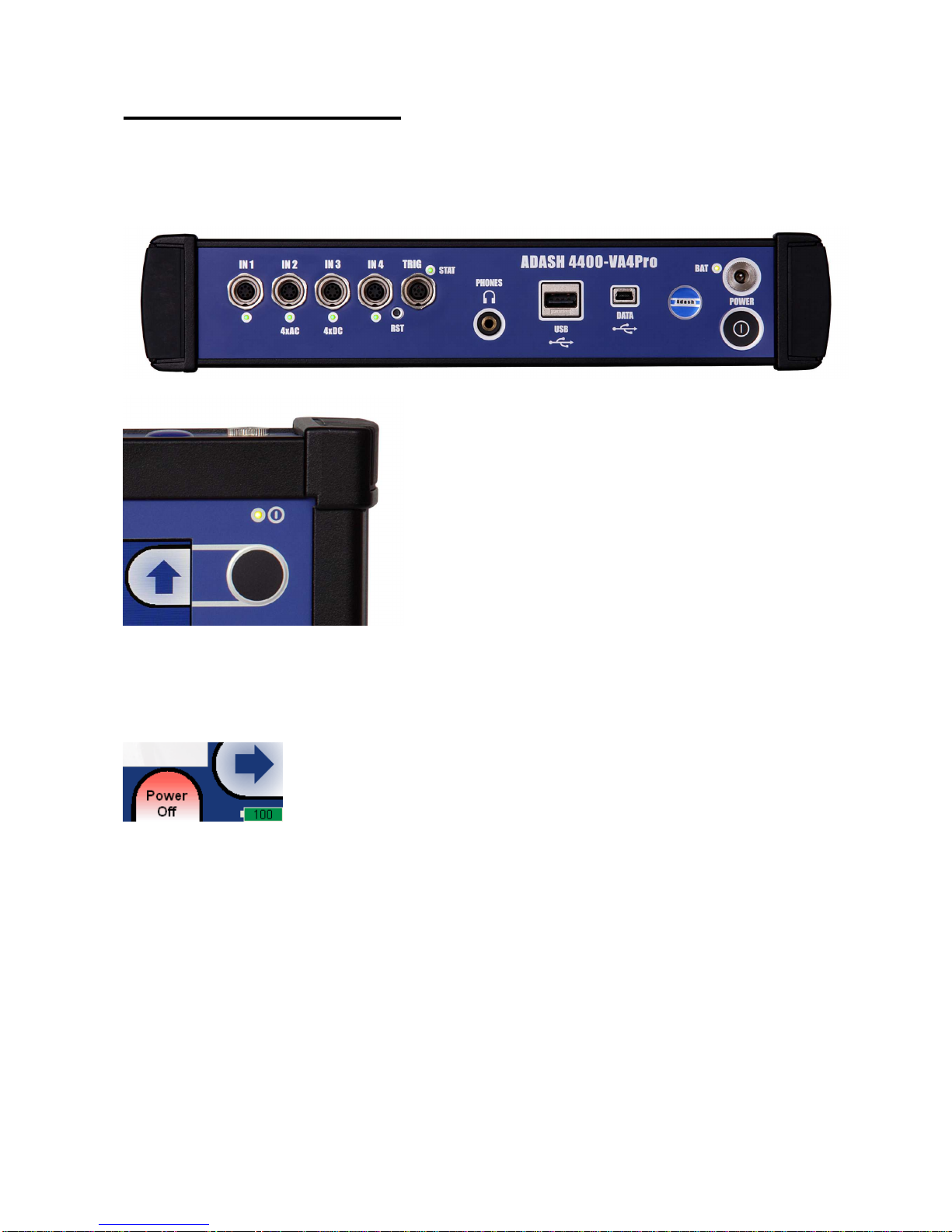
The switch-on
Use the POWER button for switch-on (older versions had the button in different position as in the picture).
The green LED on the front panel ( right at the top) lights after switch-on.
The switch off
The switching off can be done by:
- Power Off button on the main screen,
- in the Global menu is the Power Off item available.
Auto switch off
If no button is pushed in 5 minutes from switching on, the unit will be switched off.
The emergency switch off
This is not correct method to switch off the instrument. Using it can cause data corruption. Use this method only
in case of emergency (eg. when the system freezes).
Push and hold the POWER button for about 5 seconds. Instrument will switch off.
Disc free capacity warning
If this warning message appears, you need to get free disc space by removing the measurements, routes or
records, which are not actual.

ADASH Ltd. Adash 4400 – VA4Pro
11
Connection to the computer
The instrument contains the flash memory (VA4_DISC), which is accessible from external computer.
Use the USB cable, which is the standard accessory of VA4 set. Connect the small plug to the USB socket (see
the image above). Connect second plug to the computer.
The charging
The socket for external charger (instrument accessory) is above the POWER button. The BAT LED on the
upper panel lights orange during charging. When the battery is fully charged, it lights green.
The DSP board - monitoring and reset
The DSP board is the most important part of the instrument. The special chip provides all necessary operations,
which are required for achieving of 4 channel synchronous data.
The STAT LED is on the top panel and enables to monitor the DSP board (older versions had the button in
different position as in the picture). Several states can appear:
- Green with 0.25sec time interval (4Hz, four times per sec) - the measurement is running.
- Green with 1 sec time interval - STANDBY, the measurement is not running.
- Red - the DSP board does not work properly.
When the red STAT occurs, do the reset of DSP board. Do not switch-off the instrument. Use the slim not sharp
thing (e.g. paper clip) and push the button, which is hidden in the RST hole.
Next LED is near each input connector:
- green – OK
- no light – no measurement is taken in this input
- red – error (usually ICP error).
Note: During the measurement are functional only LEDs for inputs used for measurement (e.g. red LED ends
the lighting during the measurement and starts again after it).
Virtual Analyzers Data Processing
When older Analyzers would take more measurements, they took them step by step. If the user wanted e.g.
acceleration overall, velocity overall, velocity time signal and velocity spectrum from one sensor, then the
Analyzers took first overall, then second overall with integration, then time signal and finally spectrum. The time
which was required for all 4 measurements was the sum of 4 individual times.
The instrument includes high speed chips and it uses the much more advanced concept. For every individual
measurement is created one virtual Analyzer in the instrument memory. All virtual Analyzers read data from
input DSP board and perform required data acquisition.
What does it mean? It means, that the total required time is not equal the sum of all individual times, but it is
equal the time required for the longest measurement.
Run the instrument on your computer
The A4410 Virtual Unit you can download from the producer’s website. Easily unzip the zip file and run the bat
file. Now you can easy try to work with all functions in your computer. Do not forget define the record as signal
source. You can also download the next records from that website. See the A4410 Virtual Unit chapter for more
details.

ADASH Ltd. Adash 4400 – VA4Pro
12
How to work with Menu
For the taking of measurements you have to define many parameters. All those definitions are providing by
menu items. The procedure for operation with all menu items is the same. We describe it on example - the
sensor properties definition.
Item selection
The sensor properties first menu appears after you push the Sensors button.
Use the arrow buttons for one item selection, e.g. AC2. Then push OK button. The second menu appears.
Again use the arrow button for one item selection. Then push the right arrow button to display possible
parameters of selected item. E.g. for Sensitivity you see this picture:
User defined values
Again use the arrow button for one sensitivity selection (1,10,100). In most of cases you want to enter the user
sensitivity according to the real sensor sensitivity of your sensor (e.g. 96,8 mV/g). Select the user and push OK.
The next window appears and the buttons get the numerical values entry functions.

ADASH Ltd. Adash 4400 – VA4Pro
13
Use the buttons and enter required value (e.g.45). If you need to edit the value, push the Shift button. The
buttons change the functions of buttons.

ADASH Ltd. Adash 4400 – VA4Pro
14
Now you can move the cursor, to use the Delete function. Press the Shift again and the buttons functions
change back. When the value is correct, push OK. The menu with new value appears.
Use the arrows and select the Save item. Press the OK button and the working with sensors menu will close.
Also you can use the Save button with the same function. When the Cancel button is used, then nothing is
saved.
As we mentioned the value entry, also the text has to be entered in some menu items. The screen looks similar
to the numerical screen. The only difference is the characters selection on buttons. It works like mobile phones
keypad, for second character selection you must press the button two times.
Multi-selection of items
Sometimes you could need to work with more then one item together. The usual example is the deleting of more
items in one step.
The left bottom button Multi on enables to select more items at once. Press the Multi on button. When you
move in the list by arrows, the items remain selected (red color) or unselected (black color). Press the same
button (now the Multi off) again for ending of multi-selection.
Example of multi-selected items. It needs a short time to play with and to find the right understanding of this
feature. The item with the cursor (the full blue field) can be selected or unselected too. The standard yellow
color means unselecting and the red color means selecting.
Searching of item
If the list is to long or you know the name, then use the Find button. Enter the name or part of name and
confirm.
ADASH Ltd. Adash 4400 – VA4Pro
15
Input channels
All input sockets are in the top panel. The versions older then 0200 had only 3 sockets in the panel.
The input sockets labeled IN1, IN2, IN3, IN4 are used for AC or DC signals. The input socket labeled TRIG is
used for trigger signals, usually tacho. All sockets have several pins. It enables to connect more signals to one
socket (see wire diagrams).
The AC inputs enable to measure max voltage peak +/-12V. The DC channels enable to measure max +/-24V.
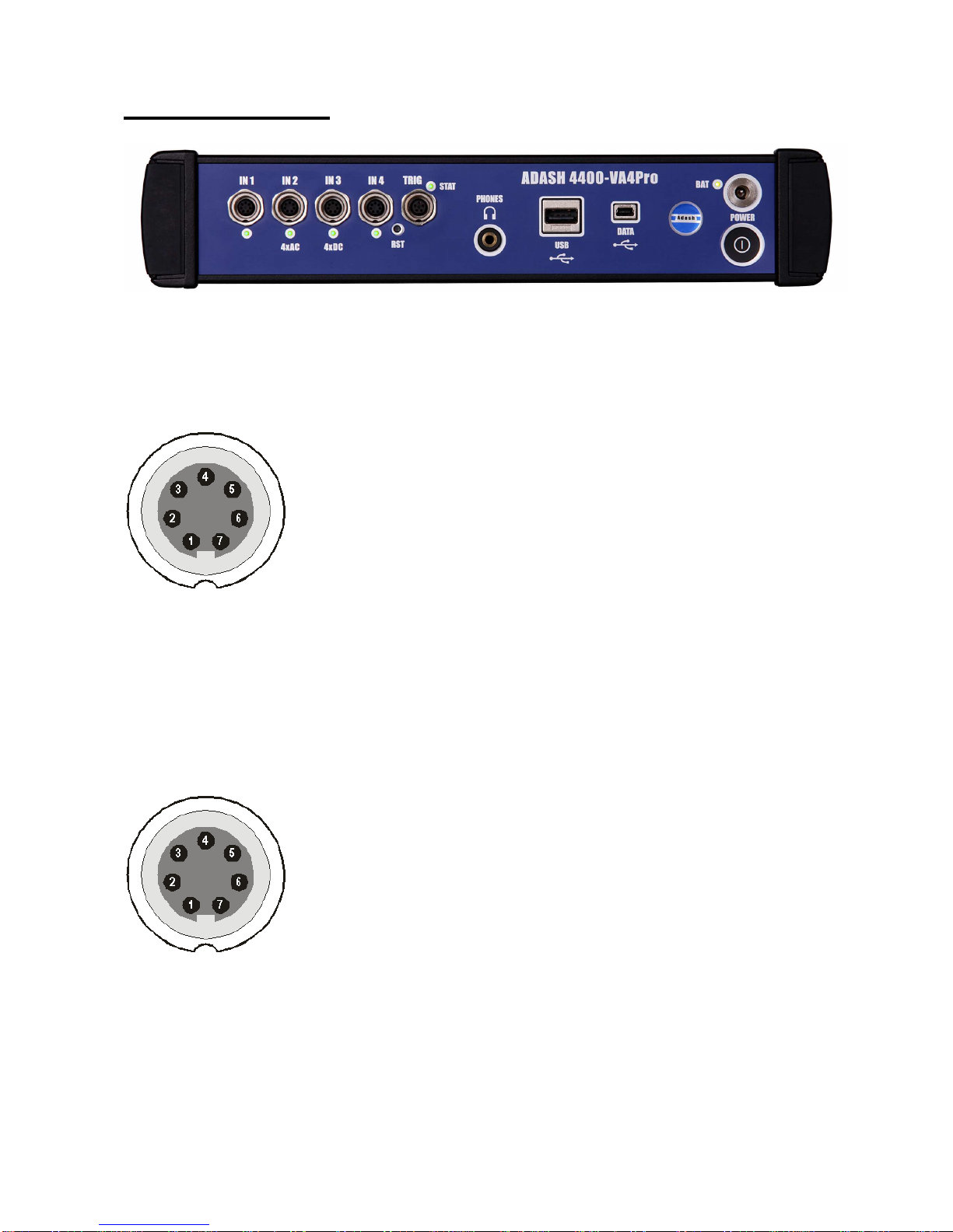
IN1 socket
1 – CH1 AC INPUT
2 – GROUND
3 – +20V DC OUTPUT (max 10mA) for eventual sensor powering
4 – SHIELDING
5 – NOT USED
6 – CH1 DC INPUT
7 – NOT USED
IN2 socket
1 – CH2 AC INPUT
2 – GROUND
3 – CH1 AC INPUT
4 – SHIELDING
5 – CH3 AC INPUT
6 – CH2 DC INPUT
7 – CH4 AC INPUT
Pay attention to possibility of connecting all four AC channels to IN2.

ADASH Ltd. Adash 4400 – VA4Pro
16
IN3 socket
1 – CH3 AC INPUT
2 – GROUND
3 – CH1 DC INPUT
4 – SHIELDING
5 – CH4 DC INPUT
6 – CH3 DC INPUT
7 – CH2 DC INPUT
Pay attention to possibility of connecting all four DC channels to IN3.
IN4 socket
1 – CH4 AC INPUT
2 – GROUND
3 – +20V DC OUTPUT (max 10mA)
4 – SHIELDING
5 – NOT USED
6 – CH4 DC INPUT
7 – NOT USED
TRIG socket
1 – GROUND
2 – NOT USED
3 – NOT USED
4 – +5 V OUTPUT/ 50 mA for tacho power supplying
5 – TRIG INPUT - for tacho signal

ADASH Ltd. Adash 4400 – VA4Pro
17
Standard cable wiring
The standard cable, which are the part of the unit, have the sensor signal connected to the pin number 1. The
second sensor wire is connected to the ground (pin 2).
When you use this cable:
In IN1 socket, the signal will be measured on CH1.
In IN2 socket, the signal will be measured on CH2.
In IN3 socket, the signal will be measured on CH3.
In IN4 socket, the signal will be measured on CH4 (ver. 2.0 and higher).
If you want to use the 3-direction sensor, then you should use the IN2 socket ( pins 3,1,5) + ground (pin 2). You
need the special cable for this purpose.

ADASH Ltd. Adash 4400 – VA4Pro
18
A4409 - BNC Box
This box can simplify the connection of more cables to VA4Pro inputs. The BNC input connectors are used on
the top panel for connection of 4 AC channels and 4 DC channels. On the side panel are two Binder connectors,
which enable to connect all 4 AC channels to IN2 input and all 4 DC channels to IN3 input.
See the wiring diagram of IN2 and IN3 in previous chapter. You see, that all 4 AC channels can be connected to
one input IN2. In the same way all 4 DC channels can be connected to one input IN3.

ADASH Ltd. Adash 4400 – VA4Pro
19
Sensors properties
When you connect the sensors to the instrument, you have to tell what kind of sensors you use. The Sensors
button is on most screens in the bottom. You can define the bearing and ISO 10816 group for every AC channel
individually.
Push the Sensors button. In the next menu select channel sensor you want define.
AC1 – AC4 setting of each AC channel properties (sensor, ISO 10816 group, bearing)
All AC Sensors setting of all AC channels together
All Bearings setting of one bearing to all AC channels
All ISO setting of one ISO 10816 group to all AC channels
DC1 – DC4 setting of each DC channel properties
All DC sensors setting of all DC channels
Tacho setting of tacho channel properties
Settling Prolongation if you need longer time for sensor settling, use this item
AC sensors
AC (alternate current) sensors are used for signals, e.g. vibrations.
ICP on, off (selection of required setting accordingly the sensor type)
Sensitivity[mV/unit] usually 1,10,100, user
Unit unit selected from the list or user unit
Position the angle of sensor (see picture bellow). Usually used for proximity sensors.

ADASH Ltd. Adash 4400 – VA4Pro
20
DC gap channel In case of displacement sensor (eddy current) also DC channel could be entered, which
is used for gap measurement ( eddy current sensor should be concurrently connected to AC and DC input).
ISO Machine Group see next chapter ISO 10816 Machine Groups
Bearing Type see Bearing Settings chapter
ISO 10816 Machine Groups
You can set the appropriate machine group according the ISO 10816 for each channel separately or for all
channels together.
ISO 10816 Classification of machinery. These parameters are used for limit values according to machine type,
nominal power or shaft height.
Bearing Settings
The fault bearing frequencies can be displayed in spectra. The bearing type definition is required for that.
Select Bearing Type item and press OK button or right arrow button. From next list select required item and
press OK button. Also recently used bearings are displayed.
Bearing type
database selection from database
Table of contents
Other Adash Measuring Instrument manuals

Adash
Adash 4300 VA3Pro User manual

Adash
Adash 4900 Vibrio III User manual

Adash
Adash A3716 User manual

Adash
Adash VA5 Pro User manual

Adash
Adash 4900 Vibrio M User manual

Adash
Adash VIBRAMON 1 User manual

Adash
Adash A4910 Lubri User manual

Adash
Adash A4900 - Vibrio M User manual

Adash
Adash A3716 User manual

Adash
Adash VA4 Pro II User manual


