ADC AD-115ES User manual

AD-115ES Installation Manual
Phase 7 / Dual Timer / S.A.F.E. System
ADC Part No. 113202-10
American Dryer Corporation
88CurrantRoad
FallRiverMA02720-4781USA
Telephone:+1(508) 678-9000/Fax: +1(508)678-9447
e-mail:techsupport@amdry.com
www.amdry.com
WARNING:Foryoursafetytheinformation
in this manual must be followed to
minimize the risk of fire or explosion and
to prevent property damage, personal
injuryordeath.
— Do not store or use gasoline or other
flammable vapors and liquids in the
vicinityof this or any otherappliance.
— WHATTO DO IFYOU SMELLGAS:
●Donottry to light any appliance.
●Donot touch anyelectricalswitch;
donot useanyphonein your
building.
●Clearthe room, building or areaof
alloccupants.
●Immediatelycall yourgassupplier
fromaneighbor’s phone. Follow
thegassupplier’sinstructions.
●Ifyoucannotreach yourgas
supplier,callthefiredepartment.
— Installation and service must be
performedbyaqualifiedinstaller,service
agencyorthe gas supplier.
AVERTISSEMENT:Assurez-vousdebien
suivrelesinstructionsdonnéesdanscette
noticepour réduire au minimum lerisque
d’incendie ou d’explosion ou pour éviter
toutdommagematériel,touteblessureou
lamort.
—Ne pas entreposer ni utiliser d’essence
nid’autresvapeursou liquides
inflammablesàproximitédecet
appareiloudetoutautreappareil.
—QUEFAIRESIVOUSSENTEZUNE
ODEURDE GAZ:
●Nepastenterd’allumerd’appareils.
●Netouchezàaucun interrupteur. Ne
pasvousservirdestéléphonesse
trouvantdanslebâtiment.
●Évacuezlapièce,lebâtimentoula
zone.
●Appelezimmédiatementvotre
fournisseurde gaz depuisunvoisin.
Suivezlesinstructionsdu fournisseur.
●Sivous ne pouvez rejoindrele
fournisseurde gaz, appelez le service
desincendies.
—L’installation et l’entretien doivent être
assurés par un installateur ou un
service d’entretien qualifié ou par le
fournisseurde gaz.

Retain This Manual In ASafe Place For Future Reference
American Dryer Corporation products embody advanced concepts in engineering, design, and safety. If this product is
properly maintained, it will provide many years of efficient, trouble free and, most importantly, safe operation.
ONLY qualified technicians should service this equipment.
OBSERVE ALL SAFETY PRECAUTIONS displayed on the equipment or specified in the installation manual included with
the dryer.
The following “FOR YOUR SAFETY” caution must be posted near the dryer in a prominent location.
“IMPORTANTNOTETOPURCHASER”
Informationmustbeobtainedfromyourlocalgassupplierontheinstructions
tobe followedif theuser smellsgas. These instructionsmustbeposted ina
prominentlocationnearthedryer.
We have tried to make this manual as complete as possible and hope you will find it useful. ADC reserves the right to make
changes from time to time, without notice or obligation, in prices, specifications, colors, and material, and to change or
discontinue models. The illustrations included in this manual may not depict your particular dryer exactly.
Important
For your convenience, log the following information:
DATEOFPURCHASE___________________________________________ MODEL NO. ______________________________
RESELLER’SNAME _______________________________________________________________________________________
Serial Number(s) ________________________________________________________________________________________
__________________________________________________________________________________________________________
__________________________________________________________________________________________________________
Replacement parts can be obtained from your reseller or the ADCfactory. Whenordering replacementpartsfrom the factory,
you canFAX your orderto ADCat +1(508) 678-9447or telephoneyour orderdirectly tothe ADCPartsDepartmentat +1(508)
678-9000. Pleasespecify the dryermodelnumberand serialnumberin addition tothe descriptionand partnumber, sothat
your order is processed accurately and promptly.
AD-115ES PH7
FOR YOUR SAFETY
Do not store or use gasoline
orother flammable vapors
andliquidsin the vicinity of
thisor any other appliance.
POUR VOTRE SÉCURITÉ
Ne pas entreposer ni utiliser d’essence
nid’autresvapeursou liquides
inflammablesàproximitédecet
appareiloudetoutautreappareil.

WARNING
UNDER NO CIRCUMSTANCES should the dryer door switches, lint drawer switch,
or heat safety circuit ever be disabled.
IMPORTANT
YOUMUSTDISCONNECTANDLOCKOUTTHEELECTRICSUPPLYANDTHEGAS
SUPPLY OR THE STEAM SUPPLY BEFORE ANY COVERS OR GUARDS ARE
REMOVED FROM THE MACHINE TO ALLOW ACCESS FOR CLEANING,
ADJUSTING, INSTALLATION, OR TESTING OFANY EQUIPMENT PER OSHA
(OccupationalSafetyand HealthAdministration)STANDARDS.
WARNING
CHILDRENSHOULD NOTBEALLOWEDTOPLAYONORNEARTHEDRYER(S).
CHILDRENSHOULDBESUPERVISEDIFNEARDRYERSINOPERATION.
CAUTION
DRYERSSHOULDNEVERBELEFTUNATTENDEDWHILEINOPERATION.
FORYOURSAFETY
DONOTDRYMOPHEADSINTHEDRYER.
DONOTUSEDRYERINTHEPRESENCEOFDRYCLEANINGFUMES.
“Caution:Label allwires prior to
disconnection when servicing
controls.Wiring errorscan cause
improper operation.”
«Attention:Aumomentde l’entretiendes commandes,
étiquetez tous les fils avant de les débrancher. Des
erreursdecâblagepeuvententraînerun fonctionnement
inadéquatetdangereux.»
Proposition65
Useof thisproduct couldexposeyou tosubstances fromfuelcombustion
thatcontainchemicalsknowntotheStateof Californiatocause cancer,
birth defects andotherreproductive harm.
▲ WARNING
!

WARNING
The dryer must never be operated with any of the back guards, outer tops, or service
panelsremoved. PERSONALINJURYORFIRECOULDRESULT.
IMPORTANT
PLEASEOBSERVEALLSAFETYPRECAUTIONSdisplayedontheequipmentand/or
specified in the installation manual included with the dryer.
WARNING
DRYERMUST NEVERBE OPERATEDWITHOUTTHELINTFILTER/SCREENIN
PLACE,EVENIFANEXTERNALLINTCOLLECTIONSYSTEMISUSED.
Dryer mustnot be installed or stored in an area where it willbe exposed to water or weather.
The wiring diagram for the dryer is located in the front electrical control box area.
IMPORTANT
Dryer must be installed in a location/environment in which the ambient temperature
remains between 40° F (4.44° C) and 130° F (54.44° C).

Table of Contents
SECTION I
SAFETY PRECAUTIONS ..............................................................................................................................2
SECTION II
SPECIFICATIONS/COMPONENT IDENTIFICATION .........................................................................4
A. Specifications.......................................................................................................................................... 4
B. Component Identification........................................................................................................................ 6
SECTION III
INSTALLATION PROCEDURES ................................................................................................................8
A. Location Requirements........................................................................................................................... 8
B. Unpacking and Setting Up...................................................................................................................... 9
C. Dryer Enclosure Requirements ............................................................................................................ 12
D. FreshAir Supply Requirements ............................................................................................................ 12
E. Exhaust Requirements.......................................................................................................................... 13
F. Electrical Information ........................................................................................................................... 17
G. Gas Information .................................................................................................................................... 21
H. Steam Information ................................................................................................................................ 25
I. Water Information ................................................................................................................................ 28
J. Preparation for Operation and Start-Up .............................................................................................. 31
K. Preoperational Test............................................................................................................................... 32
L. Preoperational Instructions ................................................................................................................... 34
M. Shutdown Instructions .......................................................................................................................... 35
SECTION IV
SERVICE/PARTS INFORMATION ...........................................................................................................36
A. Service .................................................................................................................................................. 36
B. Parts...................................................................................................................................................... 36
SECTION V
WARRANTY INFORMATION ...................................................................................................................37
A. Returning Warranty Cards ................................................................................................................... 37
B. Warranty ............................................................................................................................................... 37
C. Returning Warranty Parts..................................................................................................................... 37
SECTION VI
ROUTINE MAINTENANCE ......................................................................................................................39
A. Cleaning ................................................................................................................................................ 39
B. Adjustments .......................................................................................................................................... 40
C. Lubrication ............................................................................................................................................ 40
SECTION VII
DATA LABEL INFORMATION .................................................................................................................41
SECTION VIII
PROCEDURE FOR FUNCTIONAL CHECK OF REPLACEMENT COMPONENTS ...................42
SECTION IX
MANUAL RESET BURNER HI-LIMIT INSTRUCTIONS ..................................................................44
A. Phase 7 ................................................................................................................................................. 44
B. DualTimer ............................................................................................................................................ 44

2 American Dryer Corp. 113202-10
SECTIONI
SAFETYPRECAUTIONS
WARNING: For yoursafety,theinformation inthismanualmustbefollowedtominimizetheriskof
fireor explosionortopreventpropertydamage,personalinjury,or lossof life.
WARNING: The dryermustnever be operated withanyofthe back guards, outer tops,or
servicepanelsremoved. PERSONALINJURYORFIRE COULDRESULT.
1. DO NOT store or use gasoline or other flammable vapors and liquids in the vicinity of this or any other
appliance.
2. Purchaser/user should consult the local gas supplier for proper instructions to be followed in the event that
the user smells gas. These instructions should be posted in a prominent location.
3. WHAT TO DO IF YOU SMELL GAS:
a. DO NOT try to light any appliance.
b. DO NOT touch any electrical switch.
c. DO NOT use any phone in your building.
d. Clear the room, building, or area of ALL occupants.
e. Immediately call your gas supplier from a neighbor’s phone. Follow the gas supplier’s instructions.
f. If you cannot reach your gas supplier, call the fire department.
4. Installation and service must be performed by a qualified installer, service agency, or gas supplier.
5. Dryers must be exhausted to the outdoors.
6. Although ADC produces a very versatile dryer, there are some articles that, due to fabric composition or
cleaning method, should not be dried in it.
WARNING: Dry only water washed fabrics. DONOTdry articles spotted or washed indry
cleaningsolvents,a combustibledetergent,or“all purpose”cleaner. EXPLOSION
COULDRESULT.
WARNING: DO NOT dry rags orarticles coated or contaminatedwith gasoline, kerosene,oil, paint,
or wax. EXPLOSIONCOULD RESULT.
WARNING: DO NOTdrymop heads. Contamination bywax orflammable solvents willcreate a
firehazard.
WARNING: DO NOTuse heatfor dryingarticlesthat containplastic, foam, spongerubber,or
similarlytexturedrubbermaterials. Dryingin aheatedbasket(tumbler) maydamage
plasticsor rubber andmay create afire hazard.

113202-10 www.amdry.com 3
7. A program should be established for the inspection and cleaning of lint in the heating unit area, exhaust
ductwork, and inside the dryer. The frequency of inspection and cleaning can best be determined from
experience at each location.
WARNING: Thecollection oflint inthe burnerarea andexhaust ductworkcould createa firehazard.
8. For personal safety, the dryer must be electrically grounded in accordance with local codes and/or the
National Electrical Code ANSI/NFPA NO. 70-LATEST EDITION or in Canada, the Canadian Electrical
Codes Parts 1 & 2 CSA C22.1-1990 or LATEST EDITION.
NOTE: Failuretoelectricallyground thedryerproperly willVOIDTHEWARRANTY.
9. UNDER NO CIRCUMSTANCES should the dryer door switch, lint door switch, or the heat safety
circuit ever be disabled.
WARNING: PERSONALINJURYORFIRE COULD RESULTSHOULDTHEDRYER
DOORSWITCH, LINTDOORSWITCH,ORTHEHEATSAFETYCIRCUIT
EVERBEDISABLED.
10. This dryer is not to be used in the presence of dry cleaning solvents or fumes.
11. Remove articles from the dryer as soon as the drying cycle has been completed.
WARNING: Articlesleft inthedryer afterthedrying andcoolingcycles havebeencompleted could
createa firehazard.
12. READ AND FOLLOW ALL CAUTION AND DIRECTION LABELS ATTACHED TO THE DRYER.
13. For safety, proper operation, and optimum performance, the dryer must not be operated with a load less
than sixty-six percent (66%), 76 lb (34.5 kg), of its rated capacity.
WARNING: YOUMUSTDISCONNECTANDLOCKOUTTHEELECTRICSUPPLYAND
THEGAS SUPPLYORTHE STEAM SUPPLYBEFOREANYCOVERS OR
GUARDSARE REMOVED FROMTHE MACHINETOALLOWACCESS
FORCLEANING,ADJUSTING,INSTALLATION,ORTESTINGOFANY
EQUIPMENTPEROSHA(OccupationalSafetyandHealthAdministration)
STANDARD.
IMPORTANT: Dryer mustbeinstalledina location/environment inwhichtheambient
temperatureremainsbetween40°F(4.44°C)and130°F(54.44°C).

4 American Dryer Corp. 113202-10
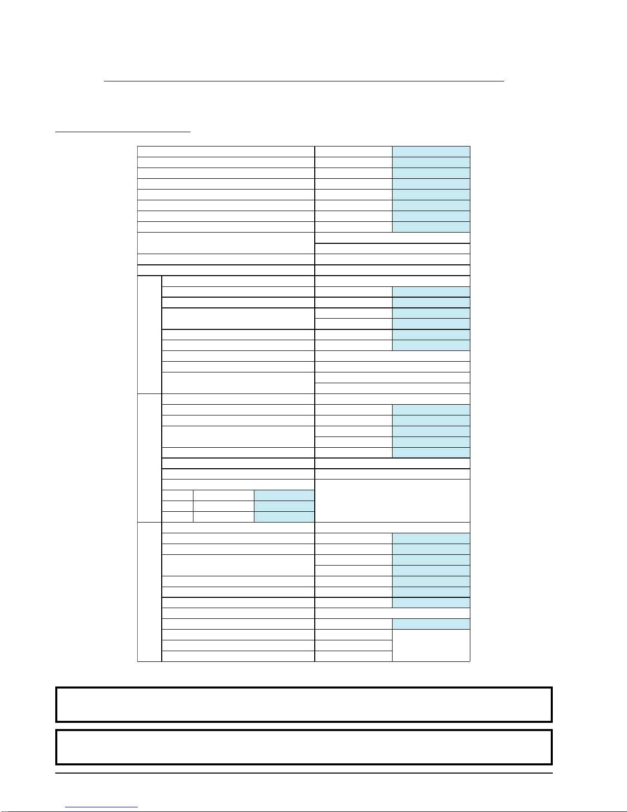
MAXIMUM CAPACITY (DRY WEIGHT) 115 lb 52.16 kg
TUMBLER DIAMETER 42” 106.68 cm
TUMBLERDEPTH 41-1/4” 104.78 cm
TUMBLER VOLUME 33.10 cu ft 937.29 L
TUMBLER/DRIVE MOTOR 3/4 hp 0.56 kW
BLOWER/FAN MOTOR 3 hp 2.24 kW
DOOR OPENING (DIAMETER) 31-3/8” 79.69 cm
DOOR SILL HEIGHT 27-1/2” 69.85 cm
WATER CONNECTION 3/4”-11.5 NH
(North America)
3/4” B.S.P.T.
(Outside North America)
DRYERS PER 20’/40’ CONTAINER 4 / 8
DRYERS PER 48’/53’ TRUCK 9 / 10
VOLTAGE AVAILABLE 208-575V 3ø 3,4w 50/60 Hz
APPROXIMATE NET WEIGHT 1,260 lb 571.53 kg
APPROXIMATE SHIPPING WEIGHT 1,400 lb 635.03 kg
AIRFLOW 60 Hz 2,100 cfm 59.47 cmm
50 Hz 1,750 cfm 49.55 cmm
HEAT INPUT 343,000 Btu/hr 86,435 kcal/hr
EXHAUST CONNECTION (DIAMETER) 14” 35.56 cm
COMPRESSED AIR CONNECTION N / A
COMPRESSED AIR VOLUME N / A
INLET PIPE CONNECTION 1” F.N.P.T.
1” F.B.S.P.T.
(CE and Australia Only)
VOLTAGE AVAILABLE 208-575V 3ø 3,4w 50/60 Hz
APPROXIMATE NET WEIGHT 1,260 lb 571.53 kg
APPROXIMATE SHIPPING WEIGHT 1,400 lb 635.03 kg
AIRFLOW 60 Hz 2,100 cfm 59.47 cmm
50 Hz 1,750 cfm 49.55 cmm
EXHAUST CONNECTION (DIAMETER) 14” 35.56 cm
COMPRESSED AIR CONNECTION N / A
COMPRESSED AIR VOLUME N / A
OVEN SIZE
kW Btu/hr kcal/hr
60 204,700 51,600
72 245,700 61,900
VOLTAGE AVAILABLE 208-575V 3ø 3,4w 50/60 Hz
APPROXIMATE NET WEIGHT 1,555 lb 705.34 kg
APPROXIMATE SHIPPING WEIGHT 1,695 lb 768.84 kg
AIRFLOW 60 Hz 2,100 cfm 59.47 cmm
50 Hz 1,750 cfm 49.55 cmm
STEAM CONSUMPTION 375 lb/hr 170.10 kg/hr
OPERATING STEAM PRESSURE 125 psi max 8.62 bar
EXHAUST CONNECTION (DIAMETER) 14” 35.56 cm
COMPRESSED AIR CONNECTION 1/4” Quick Connection
COMPRESSED AIR VOLUME 0.75 cfh 0.02 cmh
BOILER HORSEPOWER (NORMAL LOAD) 11 Bhp
SUPPLYCONNECTION 1-1/4” F.N.P.T.
RETURN CONNECTION 1-1/4” F.N.P.T.
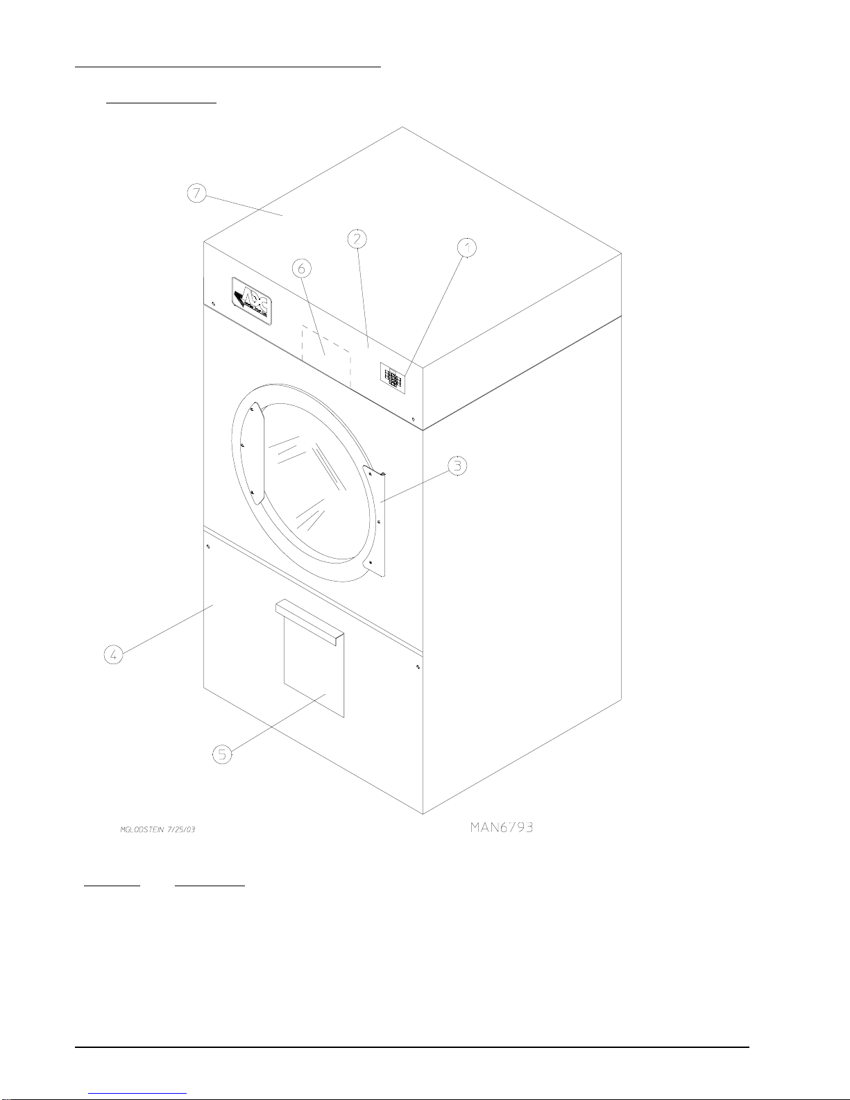
SECTIONII
SPECIFICATIONS/COMPONENTIDENTIFICATION
A. SPECIFICATIONS
Electric
Steam Gas
Shaded areas are stated in metric equivalents 5/26/06
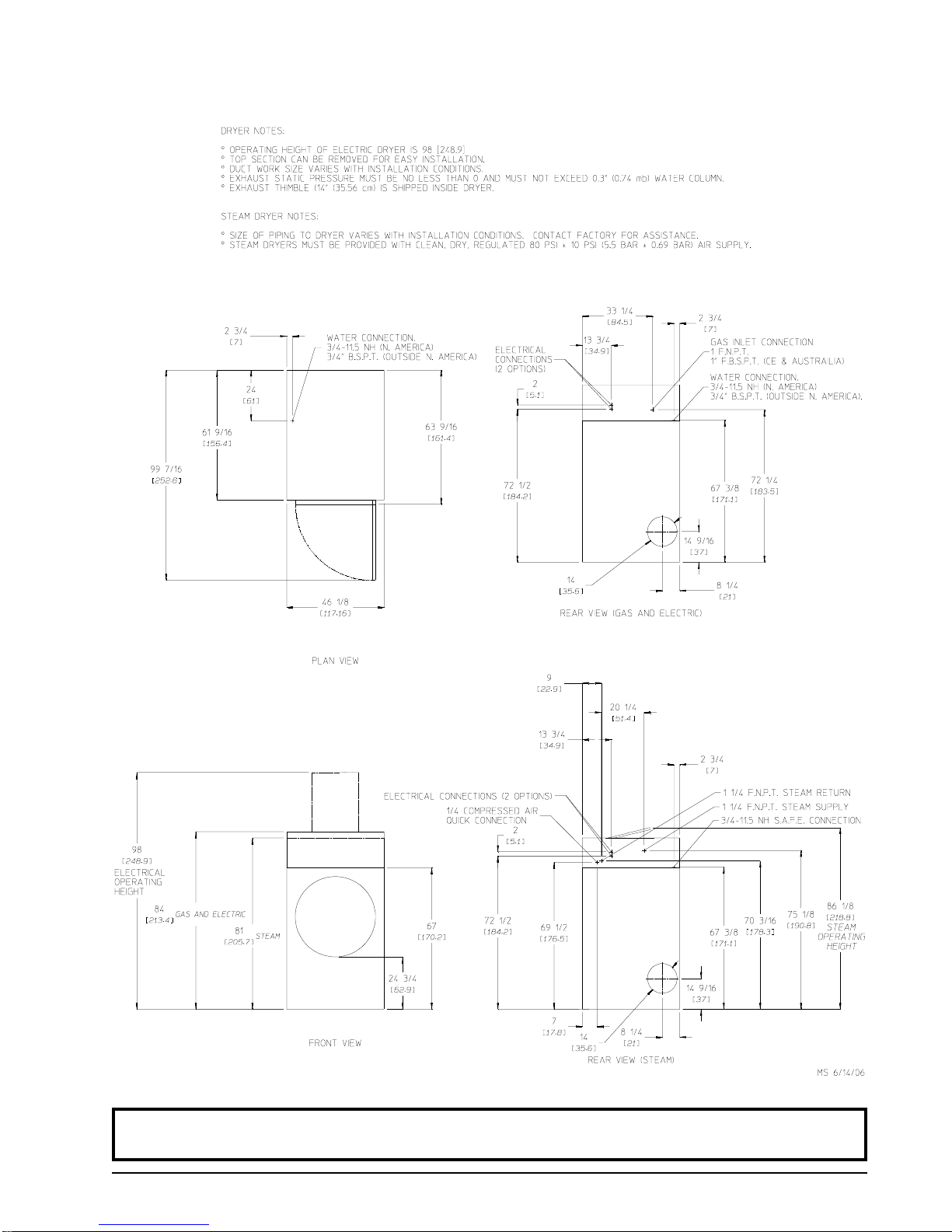
IMPORTANT: Steam dryers mustbeprovided with a clean, dry, regulated 80 psi +/- 10 psi (5.51
bar +/- 0.69 bar) air supply.
NOTE: ADCreservestheright tomakechanges inspecifications atanytime withoutnoticeor
obligation.

113202-10 www.amdry.com 5
Specifications – Gas, Electric, and Steam
NOTE: ADCreservestheright tomakechanges inspecifications atanytime withoutnoticeor
obligation.

6 American Dryer Corp. 113202-10
B. COMPONENT IDENTIFICATION
1. Dryer Front View
Illus. No. Description
1 Microprocessor Control and Keypad PanelAssembly (controls)
2 Control (top access) Door Assembly
3 Main DoorAssembly
4 Lint DoorAssembly
5 Lint Drawer
6 Wire Diagram (located behind control door)
7 Top Console (module)Assembly

113202-10 www.amdry.com 7
2. Dryer Rear View
Illus. No. Description
1 Basket (tumbler) Drive Motor Assembly
2 Blower Motor MountAssembly
3 Impellor (fan/blower)Assembly
4 Idler Bearing MountAssembly
5 Basket (tumbler) Bearing MountAssembly
6* Electric Service Relay Box
7 Heating Unit
8 Data Label and Installation Label
* Electric service connections are made in this box.

8 American Dryer Corp. 113202-10
SECTIONIII
INSTALLATION PROCEDURES
Installation should be performed by competent technicians in accordance with local and state codes. In the
absence of these codes, the installation mustconform to applicableAmerican National Standards:ANSI Z223.1-
LATEST EDITION (National Fuel Gas Code) or ANSI/NFPA NO. 70-LATEST EDITION (National Electrical
Code) or in Canada, the installation must conform to applicable Canadian Standards: CAN/CGA-B149.1-M91
(Natural Gas) or CAN/CGA-B149.2-M91 (Liquid Propane [L.P.] Gas) or LATEST EDITION (for General
Installation and Gas Plumbing) or Canadian Electrical Codes Parts 1 & 2 CSAC22.1-1990 or LATESTEDITION
(for Electrical Connections).
A. LOCATION REQUIREMENTS
Before installing the dryer, be sure the location conforms to local codes and ordinances. In the absence of such
codes or ordinances, the location must conform with the National Fuel Gas Code ANSI.Z223.1 LATEST
EDITION, or in Canada, the installation must conform to applicable Canadian Standards: CAN/CGA-B149.1-
M91 (Natural Gas) or CAN/CGA-B149.2-M91 (L.P. Gas) or LATEST EDITION (for General Installation and
GasPlumbing).
1. The dryer must be installed on a sound level floor capable of supporting its weight. Carpeting must be
removed from the floor area that the dryer is to rest on.
IMPORTANT: “Thedryer mustbeinstalledonnoncombustiblefloors only.”
2. The dryer must not be installed or stored in an area where it will be exposed to water and/or weather.
3. This dryer is for use in noncombustible locations.
4. Provisions for adequate air supply must be provided as noted in this manual (refer to Fresh Air Supply
Requirements in Section D).
5. Clearance provisions must be made from combustible construction as noted in this manual (refer to Dryer
Enclosure Requirements in Section C).
6. Provisions must be made for adequate clearances for servicing and for operation as noted in this manual
(refer to Dryer Enclosure Requirements in Section C).
7. The dryer must be installed with a proper exhaust duct connection to the outside as noted in this manual
(refer to Exhaust Requirements in Section E).
8. Dryer must be located in an area where correct exhaust venting can be achieved as noted in this manual
(refer to Exhaust Requirements in Section E).
IMPORTANT: Dryershouldbelocatedwhere aminimum amountof exhaust ductwillbe necessary.
9. The dryer must be installed with adequate clearance for air openings into the combustion chamber.
CAUTION: Thisdryer produces combustiblelint and mustbeexhaustedto the outdoors. Every6
months,inspecttheexhaustductingandremoveanylint buildup.

113202-10 www.amdry.com 9
IMPORTANT: Dryer mustbeinstalledina location/environment inwhichtheambient
temperatureremainsbetween40°F(4.44°C)and130°F(54.44°C).
B. UNPACKING AND SETTING UP
Remove protective shipping material (i.e., plastic wrap and optional shipping box) from dryer.
IMPORTANT: Dryermustbetransported andhandled inanuprightpositionat ALLtimes.
The dryer can be moved to its final location while still attached to the skid or with the skid removed. To unskid the
dryer, locate and remove the four (4) lag bolts securing the base of the dryer to the wooden skid. One (1) is
located at the rear base (remove the back panel for access), and two (2) are located in the bottom of the lint
chamber. To remove the two (2) lag bolts located in the lint chamber area, remove the lint drawer and the two (2)
Phillips head screws securing the lint door in place.
1. Leveling Dryer
To level dryer, place 4-inch (10.16 cm) square metal shims (refer to the illustration above) or other
suitable material under the base pads. It is suggested that the dryer be tilted slightly to the rear.

10 American Dryer Corp. 113202-10
2. The V-belts are disconnected from the basket drive motor for shipping. Reconnect V-belts, using the
following instructions, before starting the dryer.
a. Remove hardware holding back (belt) guard and remove guard from dryer.
b. Lay one (1) belt into motor sheave (pulley) groove and wind belt into corresponding groove of the idler
pulley by rotating the idler pulley by hand. Rotate the idler pulley an extra turn or two (2) to ensure that
the belt is tracking properly in the motor sheave (pulley) and idler pulley grooves without twisting.
c. Repeat procedure to reconnect the remaining belt.
d. Replace back (belt) guard and hardware.
3. If more headroom is needed when moving dryer into position, the top console (module) may be removed,
usingthe following instructions.
a. Disconnect the ground wire (A) at the rear upper left hand corner of dryer.
b. Remove the eight (8) sets of nuts and washers (B) holding the console (module) to base.
c. Open the control door and control panel, and disconnect the white 15-pin plug connector (C) located in
the base of the control box.
d. Disconnect white plug connector located outside backside of the control box (provides power to heat
circuit).
e. Lift the console (module) off of the dryer base.
IMPORTANT: The dryermustbe transported andhandled inan uprightposition atALLtimes.

113202-10 www.amdry.com 11
WARNING
Anexhaustducttransitionpieceisshippedinsideofthedryer’s
tumbler and MUST be installed on the dryer’s
exhaust duct, with the hardware provided, BEFORE
locationventing is connectedtothedryer.
THIS EXHAUST DUCT TRANSITION PIECE
MUST BE INSTALLED FIRST!
Failureto observe this installation requirementmay result in
damage to the dryer, create a FIRE HAZARD and will VOID
themanufacturer’s warranty.
012999JEV-GS/cj P/N: 114092
4. Exhaust Transition Piece
Inside the basket (tumbler) of this dryer is an
exhaust transition piece that must be installed on
the outlet of the exhaust before any further venting
is connected:
a. Remove the exhaust transition piece from the
basket (tumbler) and place it on the exhaust
outlet.
b. Using the screws provided, secure the exhaust
transition piece to the dryer.
NOTE: Itis recommendedthat this joint be taped
aswell asALLotherduct jointsto prevent
moistureandlintfromescapingintothe
building.

12 American Dryer Corp. 113202-10
C. DRYER ENCLOSURE REQUIREMENTS
Even though a 12-inch (30.48 cm) clearance is acceptable, it is recommended that the rear of the dryer be
positioned approximately 3 feet (0.91 meters) from the nearest obstruction (i.e., wall) for ease of installation,
maintenance, and service. Bulkheads and partitions should be made from noncombustible materials. The
clearance between the bulkhead header and the dryer must be a minimum of 4-inches (10.16 cm) and must not
extend more than 4-inches (10.16 cm) to the rear of the dryer front. The bulkhead facing must not be closed in
ALL the way to the top of the dryer. A 2-inch (5.08 cm) clearance is required.
NOTE: Bulkheadfacing shouldnotbeinstalleduntil after dryeris inplace. Ceiling areamustbe
locateda minimumof 12-inches (30.48cm) above thetop of thedryer. Eventhough a
minimumofonly 12-inches(30.48 cm)is required,18-inches (45.72 cm)or moreissuggested
forsteam dryersand especially incases where sprinklerheads are overthe dryers.
NOTE: Whenfiresprinkler systemsare locatedabove thedryers, aminimum of18-inches (45.72cm)
abovethe dryerconsole (module)is suggested. Dryersmay bepositioned sidewallto
sidewall;however, 1 or2-inches (2.54 cm or5.08 cm) issuggested between dryers (orwall)
foreaseof installationand maintenance. Allowancesmustbemadefor theopeningand
closingofthe controlandlint doors.
D. FRESH AIR SUPPLYREQUIREMENTS
When the dryer is operating, it draws in room air, heats it, passes this air through the basket (tumbler), and
exhausts it out of the building. Therefore, the room air must becontinually replenished from the outdoors. If the
make-up air is inadequate, drying time anddrying efficiency will be adversely affected. Ignition problems and sail
switch “fluttering” problems may result, as well as premature motor failure from overheating.

113202-10 www.amdry.com 13
Air supply (make-up air) must be given careful consideration to ensure proper performance of each dryer. An
unrestricted source of air is necessary for each dryer. An airflow of 2,100 cfm (cubic feet per minute) (59.5 cmm
[cubic meters per minute]) must be supplied to each dryer. As a general rule, an unrestricted air entrance from
the outdoors (atmosphere) of a minimum of 3 square feet (0.28 square meters) is required for each dryer.
To compensate for the use of registers or louvers used over the openings, this make-up air area must be
increased by approximately thirty-three percent (33%). Make-up air openings should not be located in an area
directly near where exhaust vents exit the building.
It is not necessary to have a separate make-up air opening for each dryer. Common make-up air openings are
acceptable. However, they must be set up in such a manner that the make-up air is distributed equally to ALL
the dryers. The dryer must be installed with provisions for adequate combustion and make-up air supply.
EXAMPLE: For a bank of six (6) gas dryers, two (2) openings measuring 3 feet by 3 feet (0.91 meters by 0.91
meters) are acceptable.
Allowances must be made for remote or constricting passageways or where dryers are located at excessive
altitudes or predominantly low pressure areas.
IMPORTANT: Make-up airmustbeprovided from asource freeof dry cleaningsolvent fumes.
Make-upairthatiscontaminatedbydry cleaningsolventfumeswillresultin
irreparabledamage tothe motors andother dryer components.
NOTE: Componentfailureduetodry cleaningsolventfumeswillVOIDTHEWARRANTY.
E. EXHAUST REQUIREMENTS
1. General Exhaust Ductwork Information
Exhaust ductwork shouldbe designed and installed by a qualified professional. Improperly sized ductwork
will create excessive back pressure, which results in slow drying, increased use of energy, overheating of
the dryer, and shutdown of the burner by the airflow (sail) switches, burner hi-limits, or basket (tumbler)
hi-heat thermostats. The dryer must be installed with a proper exhaust duct connection to the outside.
CAUTION: Thisdryer producescombustible lint andmustbeexhausted totheoutdoors.

14 American Dryer Corp. 113202-10
CAUTION: IMPROPERLYSIZEDOR INSTALLED EXHAUSTDUCTWORKCOULD
CREATEAFIREHAZARD.
NOTE: Whena dryer is exhausted separately, itisrecommended that a back draft damperbe
installed.
NOTE: Whendryersare exhaustedinto amultiple (common)exhaust line,each dryermustbe
suppliedwith aback draft damper.
The exhaust ductwork should be laid out in such a way that the ductwork travels as directly as possible to
the outdoors with as few turns as possible. Single or independent dryer venting is recommended. When
single dryer venting is used, the ductwork from the dryer to the outside exhaust outlet must not exceed 20
feet (6.09 meters). In the case of multiple (common) dryer venting, the distance from the last dryer to the
outside exhaust outlet must not exceed 20 feet (6.09 meters). The shape of the ductwork is not critical as
long as the minimum cross section area is provided. It is suggested that the use of 90° turns in ducting be
avoided; use 30° and/or 45° angles instead. The radius of the elbows should preferably be 1-1/2 times the
diameter of the duct. Excluding basket (tumbler) dryer elbow connections or elbows used for outside
protection from the weather, no more than two (2) elbows should be used in the exhaust duct run. If more
than two (2) elbows are used, the cross section area of the ductwork must be increased in proportion to
number of elbows added.
IMPORTANT: It is recommended that exhaust orbooster fans NOT BEUSED in the exhaust
ductworksystem.
NOTE: Asper the NationalFuel Gas Code, “Exhaustducts for type2 clothes dryers shallbe
constructedofsheetmetalorothernoncombustible material. Suchductsshall beequivalentin
strengthand corrosionresistance toducts madeof galvanizedsheet steelnot lessthan 26
gauge(0.0195-inches[0.50 mm])thick.”
ALLductwork should be smooth inside with no projections from sheet metal screws or other obstructions,
which will collect lint. When adding ducts, the ducts to be added should overlap the duct to which it is
connected. ALLductwork joints mustbetaped to prevent moisture and lint from escaping into the building.
Additionally, inspection doors should be installed at strategic points in the exhaust ductwork for periodic
inspection and cleaning of lint from the ductwork.
To protect the outside end of the horizontal ductwork from the weather, a 90° elbow bent downwardshould
be installed where the exhaust exits the building. If the ductwork travels vertically up through the roof, it
should be protected from the weather by using a 180° turn to point the opening downward. In either case,
allow at least twice the diameter of the duct between the duct opening and the nearest obstruction (i.e., roof
or ground level).
IMPORTANT: Exhaust back pressure measured bya manometer atthe dryer exhaustduct area must
beno less than 0 and mustnot exceed0.3 inches (0.74 mb) of water column
(W.C.).
NOTE: Whentheexhaust ductworkpasses throughawall, ceiling,or roofmadeof combustible
materials,the openingmust be2-inches (5.08 cm)larger thanthe duct(all the wayaround).
Theductmustbecenteredwithinthis opening.

113202-10 www.amdry.com 15
Outside Ductwork Protection
To protect the outside end of the horizontal ductwork from the weather, a 90° elbow bent downward should
be installed where the exhaust exits the building. If the exhaust ductwork travels vertically up through the
roof, it shouldbe protected from the weather by using a 180° turn to point the opening downward. In either
case, allow at least twice the diameter of the duct between the duct opening and the nearest obstruction.
IMPORTANT: DONOTuse screens,louvers, or caps on the outsideopening of the exhaust
ductwork.
2. Single Dryer Venting
When possible, it is suggested to provide a separate exhaust duct for each dryer. The exhaust duct should
be laid out in such a way that the ductwork travels as directly as possible to the outdoors with as few turns
as possible. It is suggested that the use of 90° turns in ducting be avoided; use 30° and/or 45° angles instead.
The shape of the exhaust ductwork is not critical as long as the minimum cross section area is provided.
IMPORTANT: Minimum ductsizefor agas, electric,or steamdryer withavertical runand notmore
thanthree(3) elbows(includingdryer connectionandoutside outlets)is16-inches
(40.64 cm) for a round duct or 14-1/2” by 14-1/2” (36.83 cm by 36.83 cm) for a
square duct. DUCT SIZE MUST NOT BE REDUCED ANYWHERE
DOWNSTREAM OF DRYER.
IMPORTANT: Exhaust backpressure measuredby a manometerat eachbasket (tumbler)exhaust
duct area mustbe no less than 0 and must not exceed0.3 inches (0.74 mb) of water
column(W.C.).
It is suggested that the ductwork from each dryer (minimum 14-inches [35.56 cm]) not exceed 20 feet (6.09
meters) with no more than three (3) elbows (including dryer connections and outside exhaust outlets). If the
ductwork exceeds 20 feet (6.09 meters) or has numerous elbows, the cross section area of the ductwork
must be increased in proportion to the length and number of elbows in it. In calculating duct size, the cross
section area of a square or rectangular duct must be increased by twenty percent (20%) for each additional
20 feet (6.09 meters). The diameter of a round exhaust duct should be increased ten percent (10%) for
each additional 15 feet (4.57 meters). Each 14-inch (35.56 cm) 90° elbow is equivalent to 30 feet (9.14
meters) and each 16-inch (40.64 cm) 90° elbow is equivalent to 36 feet (10.97 meters).

16 American Dryer Corp. 113202-10
IMPORTANT: For extended ductworkruns, the cross section areaof the duct can onlybe increased
toan extent. Maximumproportional ductwork runscannot exceed 20 feet(6.09
meters)morethan theoriginallimitations of20 feet(6.09meters) withtwo (2)elbows.
Whentheductworkapproaches themaximumlimitsas notedinthismanual, a
professionalheating,ventilating,andair-conditioning(HVAC)firmshouldbe
consultedforproperventinginformation.
3. Multiple Dryer (Common) Venting
If it is not feasible to provide separate exhaust ducts for each dryer, ducts from individual dryers may be
channeled into a “common main duct.” The individual ducts should enter the bottom or side of the main duct
at an angle not more than 45° in the direction of airflow and should be spaced at least 46-1/8” (117.16 cm)
apart. The main duct should be tapered, with the diameter increasing before each individual 14-inch (35.56
cm) duct is added.
IMPORTANT: The dryer isnot provided witha back draftdamper. When exhaustedinto a multiple
(common)exhaust line,a back draftdamper mustbeinstalled ateachdryer duct.
IMPORTANT: No more than four (4) dryersshould be connectedto one (1) main common duct.
The main duct may be any shape or cross-sectional area, as long as the minimum cross section area is
provided. The illustration on the following page shows the minimum cross-section area for multiple dryer
round or square venting. These figures must be increased 10 square inches (64.51 square centimeters)
when rectangular main ducting is used, and the ratio of duct width to depth should not be greater than
3-1/2 to 1. These figures must be increased proportionally if the main duct run to the last dryer to where it
exhausts to the outdoors is unusually long (over 20 feet [6.09 meters]) or has numerous elbows (more than
two [2]) in it. In calculating ductwork size, the cross-section area of a square or rectangular duct must be
increased twenty percent (20%) for each additional 20 feet (6.09 meters). The diameter of a round exhaust
mustbe increased ten percent (10%) for each additional 20 feet (6.09 meters). Each 90° elbow is equivalent
to an additional 15 feet (4.57 meters).
Other manuals for AD-115ES
1
Table of contents
Other ADC Dryer manuals
Popular Dryer manuals by other brands

Kenmore
Kenmore 417.8191 SERIES Use & care guide

Whirlpool
Whirlpool LE5760XS Use and care guide

Hoover
Hoover DX H85TCEX-AUS instruction manual

Sammic
Sammic ES-100 user manual

American Dryer Corp.
American Dryer Corp. AD-30 (Export) Installation & operator's manual

Beko
Beko DC 7110 Installation and operating instructions