ADC SL20 Gen II User manual

SL20
Installation Manual
AmericanDryerCorporation
88Currant Road
FallRiverMA02720-4781U.S.A.
Telephone:(508)678-9000 / Fax:(508)678-9447
e-mail:techsupport@amdry.com
www.amdry.com
WARNING: For your safety the information
in this manual must be followed to minimize
the risk of fire or explosion or to prevent
property damage, personal injury or death.
— Do not store or use gasoline or other flam-
mable vapors and liquids in the vicinity of this
or any other appliance.
— WHATTO DO IFYOU SMELL GAS:
• Do not try to light any appliance.
• Do not touch any electrical switch; do not
use any phone in your building.
• Clear the room, building or area of all
occupants.
• Immediately call your gas supplier from a
neighbor’s phone. Follow the gas
supplier’s instructions.
• If you cannot reach your gas supplier, call
the fire department.
— Installationandservicemustbe performed by
a qualified installer, service agency or the gas
supplier.
AVERTISSEMENT: Assurez-vous de bien
suivre les instructions données dans cette
notice pour réduire au minimum le risque
d’incendie ou d’explosion ou pour éviter tout
dommage matériel, toute blessure ou la
mort.
— Ne pas entreposer ni utiliser d’essence ni
d’autres vapeurs ou liquides inflammables à
proximité de cet appareil ou de tout autre
appareil.
— QUEFAIRESIVOUSSENTEZUNEODEUR
DEGAZ:
• Ne pas tenter d’allumer d’appareils.
• Ne touchez à aucun interrupteur. Ne pas
vous servir des téléphones se trouvant
dans le bâtiment.
• Évacuez la pièce, le bâtiment ou la zone.
• Appelez immédiatement votre
fournisseur de gaz depuis un voisin.
Suivez les instructions du fournisseur.
• Si vous ne pouvez rejoindre le
fournisseur de gaz, appelez le service
des incendies.
— L’installationet l’entretiendoiventêtreassurés
par un installateur ou un service d’entretien
qualifié ou par le fournisseur de gaz.
051603JRB/mcronan ADCPartNo.113191

Retain This Manual In A Safe Place For Future Reference
American Dryer Corporation products embody advanced concepts in engineering, design, and safety. If this product is
properly maintained, it will provide many years of safe, efficient, and trouble free operation.
ONLY qualified technicians should service this equipment.
OBSERVE ALL SAFETY PRECAUTIONS displayed on the equipment or specified in the installation manual included with
the dryer.
The following “FOR YOUR SAFETY” caution must be posted near the dryer in a prominent location.
“IMPORTANTNOTETOPURCHASER”
Informationmustbeobtainedfromyourlocalgassupplierontheinstructions
tobefollowed ifthe usersmellsgas. These instructionsmustbe postedin a
prominentlocationnearthedryer.
FORYOURSAFETY
Donot store or use gasolineor
otherflammablevaporsand
liquidsinthevicinityofthisor
anyotherappliance.
POURVOTRESÉCURITÉ
Nepas entreposerniutiliser d’essence
nid’autresvapeursouliquides
inflammablesàproximitédecet
appareilou detout autre appareil.
We have tried to make this manual as complete as possible and hope you will find it useful. ADC reserves the right to make
changes from time to time, without notice or obligation, in prices, specifications, colors, and material, and to change or
discontinue models. The illustrations included in this manual may not depict your particular dryer exactly.
Important
For your convenience, log the following information:
DATEOFPURCHASE________________________________________________ MODELNO. __________________________
RESELLER’SNAME ________________________________________________________________________________________
Serial Number(s) ________________________________________________________________________________________
________________________________________________________________________________________
________________________________________________________________________________________
Replacement parts can be obtained from your reseller or the ADC factory. When ordering replacement parts from the factory,
you can FAX your order to ADC at (508) 678-9447 or telephone your order directly to the ADC Parts Department at (508)
678-9000. Please specify the dryer modelnumberand serial numberinadditionto thedescriptionand part number, sothat
your order is processed accurately and promptly.
SL20

Important
You must disconnect and lock out the electric
supply and the gas supply before any covers or
panels are removed from the machine to allow
access for cleaning, adjusting, installation, or
testing of any equipment per OSHA
(OccupationalSafetyandHealthAdministration)
standards.
Please observe all safety precautions displayed
on the equipment and/or specified in the
installation manual included with the dryer.
Dryermust beinstalledinalocation/environment,
whichtheambient temperature remains between
40° f (4.44° c) and 130° f (54.44° c).
“Caution: Label all wires prior to disconnection when
servicing controls. Wiring errors can cause improper
operation.”
«Attention: Au moment de l’entretien des
commandes, étiquetez tous les fils avant de les
débrancher. Deserreursdecâblagepeuvent entraîner
unfonctionnementinadéquatetdangereux.»
Caution
Dryers should never be left unattended while in
operation.
Whendiscardingorstoringyouroldclothes dryer,
remove the door.
Lorsque vous entreposez ou mettez votre
sécheuse au rebut, enlevez-en la porte.
Do not allow children to play on or in the appliance.
Close supervision of children is necessary when the
applianceis used nearchildren.
Nelaissezpaslesenfantsjouerdansousurl’appareil.
Il est important de surveiller étroitement les enfants
lorsquel’appareil est utilisé non loind’enfants.
For Your Safety
Do not dry mop heads in the dryer.
Do not use dryer in the presence of dry cleaning
fumes.
Warning
Under no circumstances should the dryer main
doorswitch,lint drawer switch, or theheatcircuit
devices ever be disabled.
The dryer must never be operated with any of
the back guards, outer tops, or service panels
removed. Personal injury or fire could result.
Dryer must never be operated without the lint
filter/screen in place, even if an external lint
collection system is used.
Dryer
mustnotbe
installedorstoredinanareawhere
it will be exposed to water or weather.
Thewiring diagram forthe dryer islocated behindthe
frontcontrolpanel.
Table of Contents
SAFETY PRECAUTIONS ............................ 2
SPECIFICATIONS ....................................... 3
INSTALLATION PROCEDURES................. 4
Unpacking/Setting Up........................................... 4
Location Requirements........................................ 4
Dryer Enclosure Requirements ........................... 4
Fresh Air Supply Requirements ........................... 5
Exhaust Requirements ........................................ 5
Electrical Information............................................ 6
Gas Information .................................................... 9
Preparation for Operation/Start-up ..................... 10
Preoperational Tests .......................................... 10
Preoperational Instructions................................ 10
Shutdown Instructions........................................ 11
SERVICE/PARTS INFORMATION............ 12
Service................................................................. 12
Parts .................................................................... 12
WARRANTY INFORMATION .................... 12
Returning Warranty Cards.................................. 12
Warranty .............................................................. 12
Returning Warranty Parts ................................... 12
ROUTINE MAINTENANCE ....................... 13
DATA LABEL INFORMATION ................... 13
SENSOR ACTIVATED FIRE
EXTINGUISHING (S.A.F.E.) SYSTEM...... 14
Installation........................................................... 14
S.A.F.E. System Theory of Operation ................. 16
Disabled S.A.F.E. System................................... 16
S.A.F.E. Diagnostic Messages ........................... 16
System Reset ..................................................... 16
S.A.F.E. Parts Break Down .................................16

2113191-2
SAFETY PRECAUTIONS ___________
Warning
For your safety, the information in this manual must
befollowed to minimizetherisk of fireor explosion
or to prevent property damage, personal injury, or
lossoflife.
The dryer must never be operated with the back guard
removed. Personalinjuryor fire could result.
Do not store or use gasoline or other flammable vapors and
liquids in the vicinity of this or any other appliance.
No other fuel-burning appliance shall be installed in the same
closet as the dryer.
When discarding or storing your old clothes dryer, remove
the door.
Purchaser/user should consult the local gas supplier for
proper instructions to be followed in the event the user smells
gas. The instructions should be posted in a prominent
location.
What To Do If You Smell Gas __________
•Do not try to light any appliance.
•Do not touch any electrical switch.
•Do not use any phone in your building.
•Clear the room, building, or area of all occupants.
•Immediately call your gas supplier from a neighbor’s
phone. Follow the gas supplier’s instructions.
•If you cannot reach your gas supplier, call the fire
department.
Installation and service must be performed by a qualified
installer, service agency, or gas supplier.
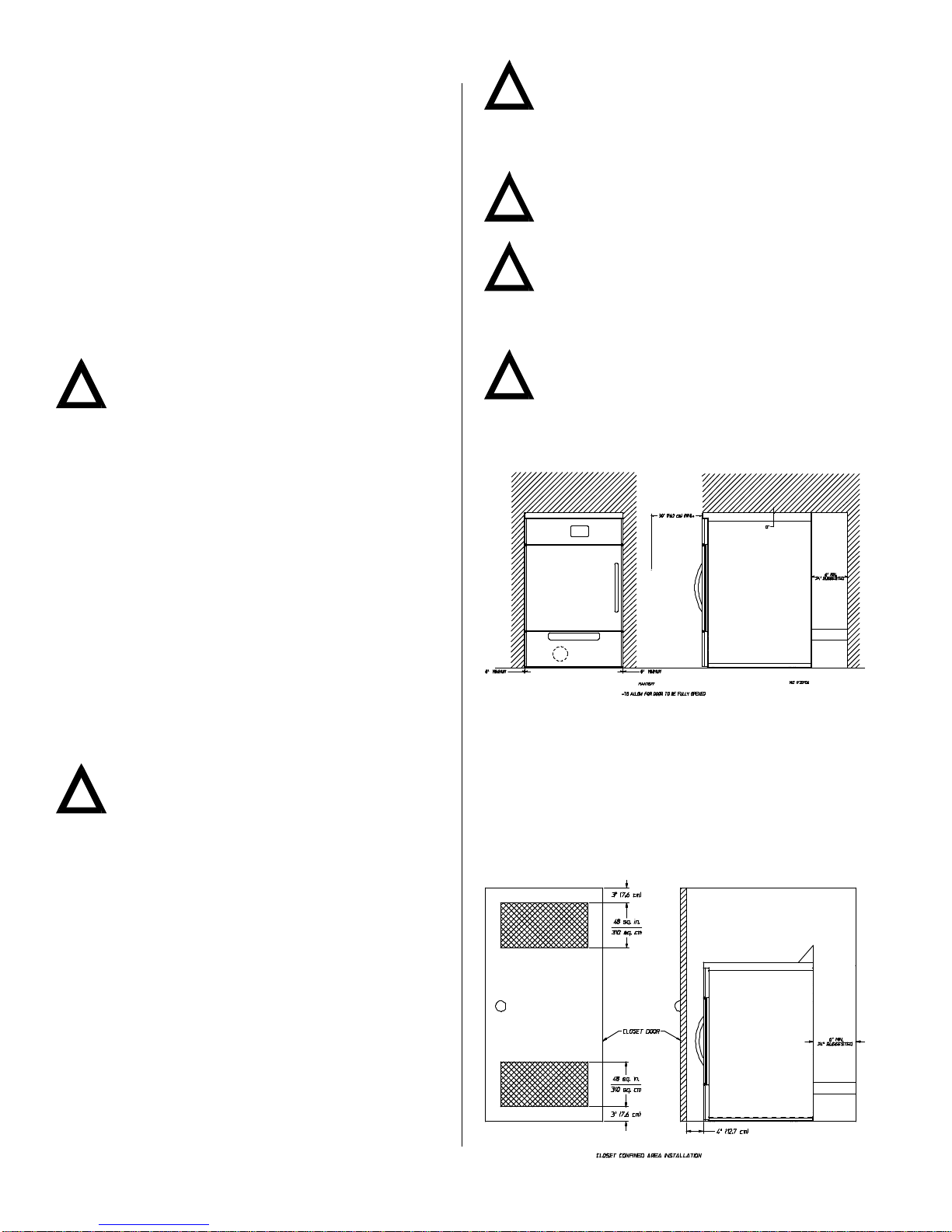
This dryer must be exhausted to the outdoors. (Cette
sécheuse doit évacuer à l’extérieur.)
AlthoughADCproducesaveryversatiledryer,therearesome
articles that, due to fabric composition or cleaning method,
should not be dried in it.
Warning
Dry only water washed fabrics. Do not dry articles
spotted or washed in dry cleaning solvents, a
combustible detergent, or “all purpose” cleaner.
Explosioncouldresult.
Do not dry rags or articles coated or contaminated with
gasoline,kerosene,oil,paint,or wax. Explosioncouldresult.
Donot drymop heads. Contaminationbywax orflammable
solventswill createa firehazard.
Warning
Donotuseheatfor dryingarticlesthatcontainplastic,
foam, sponge rubber, or similarly textured rubber
materials. Dryingin a heatedbasket (tumbler) may
damage plastics or rubber and may be a fire hazard.
A program should be established for the inspection and
cleaning of lint in the exhaust ductwork and area around the
back of the dryer. The frequency of inspection and cleaning
can best be determined from experience at each location.
Warning
Thecollectionoflintintheexhaustductworkcancreate
a potential fire hazard.
For personal safety, the dryer must be electrically grounded
in accordance with local codes and/or the National Electrical
CodeANSI/NFPANO.70-LATESTEDITIONorin Canada,the
Canadian Electrical Codes Parts 1 & 2 CSA C22.1-1990 or
LATESTEDITION.
Note
Failure to electrically ground the dryer properly will
voidthewarranty.
Under no circumstances should the dryer main door switch,
lint drawer/tray switch, or the heat circuit devices ever be
disabled.
Warning
Personal injury or fire could result should the dryer
maindoor switch,lint drawer/trayswitch, orthe heat
circuitdevices everbe disabled.
This dryer is not to be used in the presence of dry cleaning
solvents or fumes.
Remove articles from the dryer as soon as the drying cycle
has been completed.
Warning
Articles left in the dryer after the drying and cooling
cycleshavebeencompletedcancreateafirehazard.
Read and follow all caution and direction labels attached to
thedryer.
Warning
YOU MUST DISCONNECT AND LOCK OUT THE
ELECTRIC SUPPLY AND THE GAS SUPPLY
BEFOREANYCOVERSORPanelsAREREMOVED
FROMTHEMACHINETOALLOWACCESSFORCLEANING,
ADJUSTING, INSTALLATION, OR TESTING OF ANY
EQUIPMENT PER OSHA (Occupational Safety and Health
Administration)STANDARDS.
Important
Dryer must be installed in a location/environment,
which the ambient temperature remains between
40º F (4.44º C) and 130º F (54.44º C).
!
!
!
!
!
!
!
!
!

113191-2 3
SPECIFICATIONS ________________
Shaded areas are stated in metric equivalent 1/22/04
MAXIMUM CAPACITY (DRY WEIGHT) 20 lbs 9 kg
BASKET (TUMBLER) DIAMETER 25.75” 65.4 cm
BASKET (TUMBLER) DEPTH 24” 60.95 cm
BASKET (TUMBLER) VOLUME 7.5 cu ft 0.21 cu m
BASKET (TUMBLER) MOTOR 1/4 hp 0.19 kW
BLOWER MOTOR 1/8 hp 0.1 kW
CABINET WIDTH 27” 68.6 cm
CABINET DEPTH 30.59” 77.7 cm
CABINET HEIGHT 42.25” 108.6 cm
EXHAUST CONNECTION 4” 10.2 cm
HEAT INPUT 40,000 Btu/hr 10,080 kcal/hr
AIRFLOW @ 60 HZ 230 cfm 6.51 cmm
AIRFLOW @ 50 HZ 200 cfm 5.7 cmm
S.A.F.E. WATER CONNECTION 3/4”-11.5 NH
VOLTAGE AVAILABLE 120v, 208v, 230/240v / 60 Hz / 1ø
230/240v / 50 Hz / 1ø
NET WEIGHT 246.5 lbs 111.8 kg
INLET PIPE CONNECTION 3/8” M.N.P.T.
VOLTAGE AVAILABLE 208v, 230/240v / 60 Hz / 1ø
230/240v / 50 Hz / 1ø
380v, 400v, 416v / 50 Hz / 3ø
NET WEIGHT 239.5 lbs 108.6 kg
Oven Size
Voltage kW Btu/hr kcal/hr
208 4.1 13,993 3,526
208 6.1 20,819 5,246
230 5.0 17,065 4,300
230 7.4 25,255 6,364
230/240 5.4 18,430 4,644
230/240 8.1 27,644 6,966
380 6.8 23,208 5,848
400 7.5 25,597 6,450
416 8.1 27,644 6,966
Note
ADC reserves the right to make changes in
specificationsatanytimewithoutnoticeorobligation.
ELECTRIC GAS
!

4113191-2
Important
Dryer should be located where a minimum amount
ofexhaust ductwill benecessary.
The dryer must be installed with adequate clearance for air
openings into the combustion chamber.
Caution
This dryer produces combustible lint and must be
exhaustedto theoutdoors. Every 6months, inspect
the exhaust ducting and remove any lint buildup.
Important
Dryer must be installed in a location/environment,
which the ambient temperature remains between
40º F (4.44º C) and 130º F (54.44º C).
Dryer Enclosure Requirements ________
Note
Allowances must be made for opening the control
door.
Air considerations are important for proper and
efficientoperation.
Commercial Type II
X = 6-inch (15.24 cm) minimum, 24-inches (60.96 cm) is
suggested for ease of maintenance.
Dryersmay be positioned sidewallto sidewall. It issuggested
that the dryer be positioned about 2 feet (0.61 meters) away
from the nearest obstruction for ease of installation,
maintenance, and service (to be measured from the back
guard). Refer to the illustration above for details.
Domestic Type I
INSTALLATION PROCEDURES ______
Installation should be performed by competent technicians
in accordance with local and state codes. In the absence of
these codes, the installation must conform to applicable
AmericanNationalStandards:ANSI Z223.1-LATESTEDITION
(National Fuel Gas Code) or ANSI/NFPA NO. 70-LATEST
EDITION (National Electrical Code) or in Canada, the
installation must conform to applicable Canadian Standards:
CAN/CGA-B149.1-M91 (Natural Gas) or CAN/CGA-B149.2-
M91 (Liquid Propane [L.P.] Gas) or LATEST EDITION (for
General Installation and Gas Plumbing) or Canadian
Electrical Codes Parts 1 & 2 CSA C22.1-1990 or LATEST
EDITION (for Electrical Connections).
Unpacking/Setting Up __________________
Remove protective shipping material (i.e., plastic wrap and
optional shipping box) from the dryer.
Important
Dryermustbe transported and handled in an upright
positionatall times.
The dryer can be moved to its final location while still attached
to the skid or with the skid removed. To unskid the dryer,
locate and remove the two (2) bolts securing the base of the
dryer to the wooden skid.
With the skid removed, to make it easier to slide the dryer into
its final position, slightly lower all four (4) leveling legs, so
that the dryer will slide on the legs instead of the base frame.
Location Requirements ________________
Before installing the dryer, be sure the location conforms to
local codes and ordinances. In the absence of such codes
or ordinances the location must conform with the National
FuelGasCodeANSI.Z223.1LATESTEDITION,orinCanada,
the installation must conform to applicable Canadian
Standards: CAN/CGA-B149.1-M91 (Natural Gas) or CAN/
CGA-B149.2-M91(L.P.Gas)orLATEST EDITION(for General
Installation and Gas Plumbing).
The dryer must be installed on a sound level floor capable of
supporting its weight. Carpeting must be removed from the
floor area that the dryer is to rest on.
Important
“Thedryermustbeinstalled onnoncombustible floors
only.” Noncombustible floors are not required for
domesticuse.
The dryer must not be installed or stored in an area where it
will be exposed to water and/or weather.
Dryers installed in residential garages must be elevated
18-inches (45.72 cm) above the floor.
Provisionsforadequate air supply must be provided as noted
in this manual (refer toFreshAir Supply Requirements).
Clearance provisions must be made from combustible
construction as noted in this manual (refer toDryerEnclosure
Requirements).
Provisions must be made for adequate clearances for
servicing and for operation as noted in this manual (refer to
Dryer Enclosure Requirements).
The dryer must be installed with a proper exhaust duct
connection to the outside as noted in this manual (refer to
Exhaust Requirements).
Dryermust belocated inanarea wherecorrect exhaustventing
can be achieved as noted in this manual (refer to Exhaust
Requirements).
!
!
!
!
!
!

113191-2 5
Important
Make-upair mustbe providedfrom asource freeof
dry cleaning solvent fumes. Make-up air that is
contaminated by dry cleaning solvent fumes will result in
irreparable damage to the motors and other dryer
components.
Note
Componentfailureduetodry cleaningsolvent fumes
willvoidthe warranty.
Exhaust Requirements _________________
Do not use a nonmetal flexible vent or a metal vent that is
smaller than 4-inches (10.2 cm) in diameter or exhaust hoods
with magnetic latches.
The dryer shall not be exhausted into any gas vent, chimney,
wall, ceiling or concealed space of a building.
Donot installflexible ventinenclosed walls,ceilings, orfloors.
Important
Observeallgoverning codes and ordinances.
Exhaust your dryer to the outside. Moisture and lint indoors
may cause:
•Lint to gather around the dryer where it can be fuel for a
fire.
•Moisture damage to woodwork, furniture, paint, wallpaper,
carpet,etc.
•Housecleaning problems and health problems.
A4-inch(10.2 cm)diametervent isrequired. Arigidorflexible
metalvent must beused. Do not usea plastic ora foil covered
vent.
Use a heavy metal vent. Do not use a plastic or metal foil
vent. A rigid metal vent is recommended to prevent crushing
and kinking. A flexible metal vent must be fully extended and
supported when the dryer is in its final position. Remove
excess flexible vent to avoid sagging and kinking that may
result in reduced airflow.
If using an existing exhaust system, clean lint from entire
length of system. Make sure exhaust hood is not plugged
with lint. Replace any vinyl or metallized plastic foil vent with
rigid metal or flexible metal vent.
Use duct tape to seal all joints. Do not use screws or other
fastening devices that extend into the interior of the vent to
secure vent.
Service check: Back pressure in any exhaust system used
must be no less than 0 and must not exceed 0.6 inches
(1.49 mb) water column (W.C.) measured with an incline
manometer at the point that exhaust vent connects to the
dryer.
Important
Itis recommended thatexhaust or boosterfansnot
beusedin the exhaust ductwork system.
Note
Asperthe National Fuel Gas Code, “Exhaust ducts
fortype2clothesdryersshallbeconstructedofsheet
metal or other noncombustible material. Such ducts shall
be equivalent in strength and corrosion resistance to ducts
made of galvanized sheet steel not less than
0.0195-inches (26 gauge [0.05 mm]) thick.”
If a closet door is installed: unobstructed air openings are
required. The air openings shall be located 3-inches
(7.62cm) fromthe loweropening(above floorlevel) andupper
opening(belowceiling). The total free area of the air openings
in the door shall not be less than 96 square inches
(619.35squarecentimeters). Louvereddoorswith equivalent
air openings are acceptable.
No other fuel-burning appliance shall be installed in the
same closet as the dryer.
Fresh Air Supply Requirements ________
The air supply (make-up air) must be given careful
consideration to ensure proper performance of each dryer.
An unrestricted source of air is necessary for each dryer. As
a general rule, an unrestricted air entrance from the outdoors
(atmosphere) of a minimum of 1/3 square feet (0.031 square
meters) is required for each dryer. If registers or louvers are
installed over the openings, then the area must be increased.
It is not necessary to have a separate make-up air opening
for each dryer. Common make-up air openings are
acceptable. However, they must be set up in such a manner
that the make-up air is distributed equally to the dryers. The
dryer must be installed with provisions for adequate
combustion and make-up air supply.
EXAMPLE:For a bank of eight (8) dryers, two (2)
unrestricted openings measuring 1 foot by 1 foot (0.31
meters by 0.31 meters), (1 square foot [0.93 square
meters]) are acceptable.
Important
Make-up air openings should not be located in an
area directly near where exhaust vents exit the
building.
Allowances must be made for remote or constricting
passageways or where dryers are located at excessive
altitudes or predominantly low pressure areas.
!
!
!
!
!
!

6113191-2
Multiple Dryer (Common) Venting
If it is notfeasible to provide separate exhaust ducts for each
dryer, ducts from individual dryers may be channeled into a
“common main duct.” The individual ducts should enter the
bottom or side of the main duct at an angle not more than 45°
in the direction of the flow and should be spaced at least
27-inches (68.58 cm) apart.
Important
When exhausted into a multiple (common) exhaust
line, a back draft damper must be installed at each
dryer duct.
No more than four (4) dryers should be connected to one (1)
main common duct.
The main duct may be any shape or cross-sectional area, as
long as the minimum cross section area is provided. The
illustration above shows the minimum cross section area
for multiple dryer round or square venting. These figures
must be increased 10 square inches (64.52 square
centimeters) when rectangular main ducting is used, and
the ratio of duct width to depth should not be greater than
3-1/2 to 1. In calculating ductwork size, the cross-sectional
areaofa square or rectangular duct must be increased twenty
percent (20%) for each additional 20 feet (6.09 meters). The
diameter of a round exhaust must be increased ten percent
(10%) for each additional 20 feet (6.09 meters). Each
additional 90° elbow is equivalent to an additional 20 feet
(6.1 meters) and each 45° elbow is equivalent to an additional
10 feet (3.0 meters).
Warning
Dryer must never be operated without the lint filter/
screen in place, even if an external lint collection
systemisused.
Important
It is recommended that exhaust or booster fans not
beusedin the exhaust ductwork system.
Electrical Information _________________
Electrical Requirements
It is your responsibility to have all electrical connections made
by a properly licensed and competent electrician to ensure
that the electrical installation is adequate and conforms to
local and state regulations or codes. In the absence of such
codes, all electrical connections, materials, and
workmanship must conform to the applicable requirements
of the National Electrical Code ANSI/NFPA NO. 70-LATEST
EDITION or in Canada, the Canadian Electrical Codes Parts
1&2CSAC22.1-1990 orLATEST EDITION.
Horizontal Single Dryer Venting
4-inch (10.16 cm) Ducting
Vertical Single Dryer Venting
!
!
!

113191-2 7
Note
Component failure due to improper installation will
voidthewarranty.
Theuse of aluminumwire will voidthewarranty.
Important
Failure to comply with these codes or ordinances,
and/or the requirements stipulated in this manual
canresultin personal injury or component failure.
Each circuitmust beconnected toan independentlyprotected
branchcircuit.
Use only copper conductor cable of proper ampacity and
insulationinaccordancewithelectriccodesformakingservice
connections.
A separate circuit servicing each dryermust beprovided.
Electrical Service Specifications
Important
The wire size must be properly sized to handle the
related current.
Thedryer mustbe connectedto theelectric service/
supplyshownon the dryer data label.
Note
Manufacturer reserves the right to make changes in
specificationsatanytimewithoutnoticeorobligation.
Component failure due to improper voltage
applicationwillvoidthewarranty.
GasModels
1/22/04
!
!
!
!
ElectricModels
The connecting wires must be properly sized to handle the
rated current.
1/22/04
Grounding
A ground (earth) connection must be provided and installed
in accordance with state and local codes. In the absence of
these codes, grounding must conform to applicable
requirements of the National Electrical Code ANSI/NFPA NO.
70-LATEST EDITION, or in Canada, the installation must
conform to applicable Canada Standards: Canadian Electrical
Codes Parts 1 & 2 CSA C22.1-1990 or LATEST EDITION.
The ground connection may be to a proven earth ground at
the location service panel.
For added personal safety, when possible, it is suggested
that a separate ground wire (no. 18 minimum) be connected
from the ground connection of the dryer to a grounded cold
water pipe. Do not ground to a gas pipe or hot water pipe.
The grounded cold water pipe must have metal-to-metal
connection all the way to the electrical ground. If there are
any nonmetallic interruptions, such as, a meter, pump, plastic,
rubber, or other insulating connectors, they must be jumped
out with no. 4 copper wire and securely clamped to bare
metal at both ends.
Important
For personal safety and proper operation, the dryer
must be grounded.
Provisions are made for ground connection in each dryer at
the electrical service connection area.
Note
Anindividualmanualshutoffvalve mustbe installed
within 6 feet (1.8288 meters) of the dryer in
accordancewiththeNationalFuel GasCode, ANSI
Z223.1/NFPA54.
GAS
ELECTRICAL SERVICE SPECIFICATIONS (PER DRYER)
NOTES: A.
B.
C.
When fuses are used they must be dual element, time
delay, current limiting, class RK1 or RK5 ONLY.
Calculate/determine correct fuse value, by applying
either local and/or National Electrical Codes to listed
appliance amp draw data.
Circuit breakers are thermal-magnetic (industrial) motor
curve type ONLY. For others, calculate/verify correct
breaker size according to appliance amp draw rating
and type of breaker used.
Circuit breakers for 3-phase (3Ø) dryers must be
3-pole type.
SERVICE
VOLTAGE PHASE WIRE
SERVICE
APPROX.
AMP DRAW CIRCUIT
BREAKER
60 Hz 50 Hz
120 1ø 28.4 --- 15
208 1ø 24.3 --- 15
230 1ø 2--- 4.8 15
240 1ø 24.7 5.0 15
ELECTRIC
ELECTRICAL SERVICE SPECIFICATIONS (PER DRYER)
NOTES: A.
B.
C.
When fuses are used they must be dual element, time
delay, current limiting, class RK1 or RK5 ONLY.
Calculate/determine correct fuse value, by applying
either local and/or National Electrical Codes to listed
appliance amp draw data.
Circuit breakers are thermal-magnetic (industrial) type
ONLY. For others, calculate/verify correct breaker size
according to appliance amp draw rating and type of
breaker used.
Circuit breakers for 3-phase (3Ø) dryers must be
3-pole type.
SERVICE
VOLTAGE PHASE WIRE
SERVICE
APPROX.
AMP DRAW CIRCUIT
BREAKER
60 Hz 50 Hz
208 (4.1 kW) 1ø 224.0 -- 30
208 (6.1 kW) 1ø 233.6 -- 40
230 (5.0 kW) 1ø 2-- 26.0 30
230 (7.4 kW) 1ø 2-- 36.5 45
240 (5.4 kW) 1ø 227.2 27.5 30
240 (8.1 kW) 1ø 238.5 38.8 45
380 (6.8 kW) 3ø 4-- 14.9 20
400 (7.5 kW) 3ø 4-- 15.6 20
416 (8.1 kW) 3ø 4-- 16.2 20
!
!

8113191-2
Warning
Electrical Grounding Instructions – This dryer is
equipped with a three-prong (grounding) plug for
your protection against shock hazard and should
be plugged directly into a properly grounded three-prong
receptacle. Do not cut or remove the grounding prong from
thisplug.
Electrical Connections
A wiring diagram is located inside the control panel.
Note
Acircuitservicing each dryer must be provided.
The electrical input connections on all dryers are made into
the rear service box located at the upper right area of the
dryer.
If local codes permit, power to the dryer can be made by the
use of a flexible U.L. listed power cord or pigtail (wire size
must conform to rating of dryer), or the dryer can be hard
wired directly to the service breaker panel. In both cases, a
strain relief must be installed where the wiring enters the
dryer.
GasModels
Single-Phase (1ø) Wiring Connections/Hookup
!
!
Electric Models Only
Single-Phase (1ø) Wiring Connections/Hookup
3-Phase (3ø) Wiring Connections/Hookup

113191-2 9
Gas Information ________________________
Itis your responsibilitytohave all plumbingconnections made
by a qualified professional to ensure that the gas plumbing
installation is adequate and conforms to local and state
regulations or codes. In the absence of such codes, all
plumbing connections, materials, and workmanship must
conform to the applicable requirements of the National Fuel
GasCode ANSIZ223.1-LATEST EDITION,or inCanada, the
Canadian Installation Codes CAN/CGA-B149.1-M91 (Natural
Gas)orCAN/CGA-B149.2-M91(LiquidPropane [L.P.]Gas) or
LATESTEDITION.
The dryer must be disconnected from the gas supply piping
system during any pressure testing of that system at test
pressures in excess of 1/2 psig (3.5 kPa). The dryer must be
isolated from the gas supply piping system by closing an
external manual shutoff valve during any pressure test of the
gas supply system at test pressures equal to or less than
1/2 psig (3.5 kPa).
Important
Failure to comply with codes or ordinances, and/or
requirementsinthis manual, can result in personal
injury and improper operation of the dryer.
Failuretoisolateordisconnect thedryerfromsupplyas noted
can cause irreparable damage to the gas valve, which will
voidthewarranty.
Warning
Fireorexplosioncouldresult duetofailureofisolating
ordisconnecting thegassupply asnoted.
Gas Supply
The gas dryer installation must meet the American National
Standard...National Fuel Gas Code ANSI Z223.1-LATEST
EDITION,or in Canada,the Canadian InstallationCodesCAN/
CGA-B149.1M91 (NaturalGas)or CAN/CGA-B149.2-M91(L.P.
Gas) or LATEST EDITION, as well as local codes and
ordinances and must be done by a qualified professional.
Note
Undersizedgaspipingwillresultinignitionproblems,
slowdrying,increaseduseofenergy,andcancreate
asafetyhazard.
Thedryermust be connected to the type of heat/gas indicated
on the dryer data label. If this information does not agree
withthetype ofgasavailable, Donotoperatethedryer. Contact
the reseller who sold the dryer or contact the ADC factory.
The input ratings shown on the dryer data label are for
elevations up to 2,000 feet (609.6 meters), unless elevation
requirementsof over2,000 feet(609.6 meters)were specified
at the time the dryer order was placed with the factory. The
adjustment or conversion of dryers in the field for elevations
over 2,000 feet (609.6 meters) is made by changing each
burner orifice. If this conversion is necessary, contact the
reseller who sold the dryer or contact the ADC factory.
Important
Any burner changes or conversions must be made
byaqualified professional.
This gas dryer is not provided with an internal gas
supply shutoff and an external gas supply shutoff must be
provided.
!
!
!
!
Technical Gas Data
Gas Specifications
Shaded areas are stated in metric equivalents
* Measured at outlet side of gas valve pressure tap when gas valve is on.
Gas Connections
Inlet connection ..................... 3/8”M.P.T.
Inlet supply size ..................... 3/8” Pipe (minimum)
Btu/hr input (per dryer) .......... 40,000 (10,080 kcal/hr)
NaturalGas
Regulation is controlled by the dryer’s gas valve’s internal
regulator. Incoming supply pressure must be consistent
between a minimum of 6.0 inches (14.92 mb) and a maximum
of 12.0 inches (29.9 mb) water column (W.C.) pressure.
LiquidPropane (L.P.) Gas
Dryersmade for use withL.P. gas have thegas valve’s internal
pressure regulator blocked open so that the gas pressure
must be regulated upstream of the dryer. The pressure
measured at each gas valve pressure tap must be a
consistent 10.5 inches (26.1 mb) water column. There is no
regulator or regulation provided in an L.P. dryer. The water
column pressure must be regulated at the source (L.P. tank)
or an external regulator must be added to each dryer.
Shaded area is stated in metric equivalent
* Drill Measurement Size (D.M.S.) equivalents are as follows:
Natural Gas ................#31 =0.1200” (3.048 mm).
Liquid Propane Gas ...#49 =0.0730” (1.8542 mm).
For use with natural gas and propane, a conversion kit,
as supplied by the manufacturer, shall be used to convert
this dryer to the alternate fuel.
Pour utilisation avec le gaz naturel ou le propane. Utilisez
la trousse de conversion fournie par le fabricant pour
passer d’un combustible à l’autre.
Piping Connections
All components/materials must conform to National Fuel Gas
Code Specifications ANSI Z223.1-LATEST EDITION, or in
Canada, CAN/CGA-B149.1-M91 (Natural Gas) or CAN/CGA-
B149.2-M91 (L.P. Gas) or LATEST EDITION (for General
Installation and Gas Plumbing), as well as local codes and
ordinances and must be done by a qualified professional. It
is important that gas pressure regulators meet applicable
pressure requirements, and that gas meters be rated for the
total amount of all the appliance Btus being supplied.
The dryer is provided with a 3/8” M.P.T. inlet pipe connection
located at the left side of the base of the dryer, when viewing
from the rear. The minimum pipe size (supply line) to the
dryer is 3/8” diameter. For ease in servicing, the gas supply
line of each dryer must have its own shutoff valve.
TYPE OF GAS
NATURAL LIQUID PROPANE
Manifold Pressure* 3.5 inches W.C. 8.7 mb 10.5 inches W.C. 26.1 mb
In-Line Pressure 6.0 - 12.0 inches W.C. 14.92 - 29.9 mb 11.0 inches W.C. 27.4 mb
TYPE OF GAS Liquid
Propane
Conversion Kit
Part Number
Btu/hr
Rating kcal/hr
Rating Natural Liquid Propane
Qty. D.M.S.* Part No. Qty. D.M.S.* Part No.
40,000 10,080 1 #31 140868 1#49 140869 883610

10 113191-2
Important
The gas supply line to each dryer must be a minimum
of 3/8-inch (9.5 mm). Do not reduce this pipe size
requirement.
The size of the main gas supply line (header) will vary
depending on the distance this line travels from the gas meter
or, in the case of liquid propane (L.P.) gas, the supply tank,
othergas-operated appliances onthesame line, etc. Specific
information regarding supply line size should be determined
by the gas supplier.
Note
Undersized gas supply piping can create a low or
inconsistent pressure, which will result in erratic
operation of the burner ignition system.
Consistent gas pressure is essential at all gas connections.
It is recommended that a 1/2” (12.7 mm) pipe gas loop be
installed in the supply line servicing a bank of dryers. An
in-line pressure regulator must be installed in the gas supply
line (header) if the (natural) gas pressure exceeds
12.0 inches (29.9 mb) of water column (W.C.) pressure.
A 1/8” N.P.T. plugged tap, accessible for a test gauge
connection, must be installed in the main gas supply line
immediately upstream of each dryer.
Important
The dryer and its individual shutoff valve must be
disconnected from the gas supply piping system
during any pressure testing of that system at test
pressuresin excess of1/2 psig (3.5kPa).
Pipejointcompoundsthatresist theactionofnaturalgas and
L.P. gas must beused.
Testallconnections for leaks by brushing on a soapy water
solution(liquid detergentworks well).
Warning
Nevertest forleakswith aflame!!!
Note
A water column test pressure of 3.5 inches (8.7 mb)
for natural gas and 10.5 inches (26.1 mb) for L.P.
dryers is required at the gas valve pressure tap of
each dryer for proper and safe operation.
Thedryermustbe isolatedfromthegas supplypipingsystem
by closing its individual manual shutoff valve during any
pressuretestofthegas supplysystemattestpressures equal
to or less than 1/2 psig (3.5 kPa).
Preparation For Operation/Start-Up ___
The following items should be checked before attempting to
operate the dryer:
•Read all “CAUTION,” “WARNING,” and “DIRECTION”
labels attached to the dryer.
•Check incoming supply voltage to be sure that it is the
same as indicated on the dryer data label.
•GasModels –check toensure thatthe dryeris connected
to the type of heat/gas indicated on the dryer data label.
•Gas and Electric Models – the sail switch damper
assembly was installed and adjusted at the factory prior
to shipping. However, each sail switch adjustment must
be checked to ensure that this important safety control is
functioning.
•Check bolts, nuts, screws, terminals, and fittings for
tightness.
•Gas Models – be sure that all gas shutoff valves are in
the open position.
•Check that the back guard panel and the electrical box
cover have been replaced.
•Check the lint drawer/tray to ensure that it is closed and
secured in place.
•Rotate the basket (tumbler/drum) by hand to be sure it
movesfreely.
•Check terminals and fittings for security.
Preoperational Tests ___________________
All dryers are thoroughly tested and inspected before leaving
the factory. However, a preoperational test should be
performed before the dryer is publicly used. It is possible
that adjustments have changed in transit or due to marginal
location (installation) conditions.
Turn on electric power to the dryer.
Refer to the Operating Instructions for starting your particular
modeldryer.
Gas Models Only
When a gas dryer is first started (during initial start-up), it has
a tendency not to ignite on the first ignition attempt. This is
because the gas supply piping is filled with air, so it may take
a few minutes for the air to be purged from the lines.
Note
During the purging period, check to be sure that all
gasshutoffvalves are open.
Important
There is no regulator provided in a L.P. dryer. The
water column pressure must be regulated at the
source (L.P. tank), or an external regulatormust be
addedtoeach dryer
Make a complete operational check of all safety related
circuits:
•Door Switch(es)
•Hi-Limit Thermostats
•Cycling Thermostat
•Gas And Electric Models Only – Sail Switch
Make a complete operational check of all operating controls.
Note
If computer program changes are required, refer to
the computer programming section of the manual
suppliedwiththe dryer.
The dryer should be operated through one (1) complete cycle
to ensure that all components are functioning properly.
Preoperational Instructions ____________
Coin Models
Microprocessor Controller (Computer)
Whenthe microprocessorcontroller (computer)is inthe ready
state, the liquid crystal display (L.C.D.) screen will display
“Ready,Insert$XX.XX (amount) to Start”.
Insert coin(s). Once the correct “Amount to Start” has been
inserted, the L.C.D. will display “Select Temperature”.
Select temperature by pressing “HI,” “MED,” or “LO.” The
cyclewillstart andtheL.C.D.willdisplaytheDryCycleselected
and the remaining time.
!
!
!
!
!
!
!
!

113191-2 11
The dryer will continue through the drying and cooling cycles,
until the vended time has expired.
Note
Tostop dryer,open maindoor orpressing thepause
key. Continuationof thecycle willresume onlyafter
the door has been closed and any of the three (3)
temperatureselectionis pressed.
Upon completion of the drying and cooling cycles, the tone
(buzzer) will sound and the dryer will go into the Anti-Wrinkle
Modefor99 minutes, or until the main door has beenopened.
Important
For more detailed information regarding the
microprocessorcontroller (computer)on yourdryer,
referto themicroprocessoruser’s manualincluded
withthedryer.
Non-Coin Models
The light emitting diode (L.E.D.) display reads “READY” (no
cycle in progress).
Press the letter on the keyboard (touch pad) corresponding
to the cycle desired (i.e., key “D”).
Note
“0-40” will require the “START/ENTER”
l
key to be
pressed after the number is selected in order to
acceptthe selectionand startdrying.
The dryer will then start. (i.e., blower, basket [tumbler], and
heat).
TheL.E.D.display willreadMANUAL DRYINGCYCLED,00:00
MINREMAIN.
Note
Press and hold the “UP ARROW” to view the basket
(tumbler) temperature at any time.
The dryer can be stopped at any time by pressing
the “STOP/CLEAR”
O
key, atthis timethedryer willgo intoa
cycle pause. If the “STOP/CLEAR”
O
keyis pressed again
atthis point, the cyclethat was in progresswill be cancelled
andreturnedto the “READY” state.
Press and hold the “DOWN ARROW” to view the basket
(tumbler)RPM.
When the programmed drying time has expired, the Phase 7
non-coin microprocessor controller (computer) will proceed
into the Cool Down Cycle.
Once the Cool Down Cycle begins at the end of the heat
cycle, the L.E.D. display will read COOL DOWN TEMP
___/___ MINUTES remaining. At the end of the heat cycle,
the dryer will shut off the heat and continue the fan and basket
(tumbler)until theCool DownTime ortemperature isreached.
Important
For more detailed information regarding the
microprocessorcontroller (computer)on yourdryer,
referto themicroprocessoruser’s manualincluded
withthedryer.
!
!
!
!
!
Shutdown Instructions _________________
If the dryer is to be shutdown (taken out of service) for a
period of time, the following must be performed:
Discontinuepower tothe dryereither atthe externaldisconnect
switch or the circuit breaker.
Discontinue the heat supply:
Gas Models - discontinue the gas supply.
Shut off external gas supply shutoff valve.

12 113191-2
SERVICE/PARTS INFORMATION ____
Service _________________________________
Service must be performed by a qualified trained technician,
serviceagency,or gas supplier. If service is required, contact
the reseller from whom the ADC equipment was purchased.
If the reseller cannot be contacted or is unknown, contact the
ADC Service Department for a reseller in your area.
Note
When contacting the ADC Service Department, be
sure to give them the correct model number and
serial number so that your inquiry is handled in an
expeditiousmanner.
Parts ___________________________________
Replacement parts should be purchased from the reseller
from whom theADC equipmentwaspurchased. Ifthereseller
cannot be contacted or is unknown, contact the ADC Parts
Department for a reseller in your area. Parts may also be
purchased directly from the factory by calling the ADC Parts
Department at (508) 678-9000 or you may FAX in your order
at (508) 678-9447.
Note
When ordering replacement parts from the ADC
reseller or theADCfactorybesureto givethemthe
correct model number and serial number so that
yourparts ordercan beprocessed inan expeditiousmanner.
WARRANTY INFORMATION ________
Returning Warranty Cards _____________
Before any dryer leaves theADC factory test area, a warranty
cardis placed on thebackside of the maindoor glass. These
warranty cards are intended to serve the customer where we
record the individual installation date and warranty information
to better serve you should you file a warranty claim.
If a warranty card did not come with your dryer, contact the
ADC Warranty Department or theADC ServiceDepartmentat
(508)678-9000.
Important
A separate warranty card must be completed and
returnedforeach individual dryer.
Note
Besuretoincludetheinstallationdate whenreturning
thewarrantycard(s).
Warranty _______________________________
For a copy of the ADC commercial warranty covering your
particular dryer(s), contact the ADC reseller from whom you
purchased the equipment and request a dryer warranty form.
If the reseller cannot be contacted or is unknown, warranty
information can be obtained from the factory by contacting
the ADC Warranty Department at (508) 678-9000.
Note
Whenever contacting the ADC factory for warranty
information, be sure to have the dryer’s model
number and serial number available so that your
inquiry can be handled in an expeditious manner.
Returning Warranty Parts _____________
AllL dryer or parts warranty claims or inquiries should be
addressed to the ADC Warranty Parts Department. To
expedite processing, the following procedures must be
followed:
No parts are to be returned to ADC without prior written
authorization (“Return Material Authorization” [R.M.A.]) from
thefactory.
Note
AnR.M.A.isvalidforonlythirty (30)days fromdate of
issue.
The R.M.A. issued by the factory, as well as any other
correspondence pertaining to the returned part(s), must be
included inside the package with the failed merchandise.
Each part must be tagged with the following information:
•Model number and serial number of the dryer from which
part was removed.
•Nature of failure (be specific).
•Date of dryer installation.
•Date of part failure.
•Specify whether the part(s) being returned is for a
replacement, a credit, or a refund.
Note
Ifa partismarked fora credit ora refund, theinvoice
number covering the purchase of the replacement
part must be provided.
Warrantytags(ADC P/N450064)are availableat“nocharge”
fromADC uponrequest.
The company returning the part(s) must clearly note the
complete company name and address on the outside of the
package.
All returns must be properly packaged to ensure that they are
not damaged in transit. Damage claims are the responsibility
of the shipper.
Important
No replacements, credits, or refunds will be issued
for merchandise damaged in transit.
All returns should be shipped to the ADC factory in such a
manner that they are insured and a proof of delivery can be
obtained by the sender.
Shippingchargesare not the responsibility ofADC. Allreturns
shouldbe“prepaid”tothe factory. Any“C.O.D.”or“COLLECT”
returns will not be accepted.
Important
Noreplacements, credits,or refundswill beissued if
the claim cannot be processed due to insufficient
information. Thepartyfilingtheclaim willbenotified
in writing, either by “FAX” or “CERTIFIED MAIL – Return
Receipt Requested,” as to the information necessary to
process claim. If reply is not received by theADC Warranty
Department within thirty (30) days from the FAX/letter date,
thenno replacements, credits,orrefunds will beissued, and
themerchandisewill be discarded.
!
!
!
!
!
!
!
!
!

113191-2 13
DATALABEL INFORMATION _______
When contacting American Dryer Corporation, certain
information is required to ensure proper service/parts
information from ADC. This information is on the data label
that is affixed to the rear upper left back area of the dryer,
whichcan be viewed eitherthrough the openingsinthe dryer’s
back panel/guard, or by removing this back panel/guard.
When contacting ADC, please have the model number and
serial number available.
1. MODEL NUMBER
The model number is an ADC number, which describes the size
of the dryer and the type of heat (gas, electric, or steam).
2. SERIAL NUMBER
The serial number allows ADC to gather information on your
particular dryer.
3. MANUFACTURING CODE NUMBER
The manufacturing code number is a number issued by ADC,
which describes all possible options on your particular model.
4. TYPE OF HEAT
This describes the type of heat for your particular dryer: gas
(either natural gas or liquid propane [L.P.] gas), electric, or
steam.
5. HEAT INPUT (FOR GAS DRYERS)
This describes the heat input in British Thermal Units per Hour
(Btu/hr).
6. ORIFICE SIZE (FOR GAS DRYERS)
Gives the number drill size used.
7. ELECTRIC SERVICE
This describes the electric service for your particular model.
8. GAS MANIFOLD PRESSURE (FOR GAS DRYERS)
This describes the manifold pressure taken at the gas valve tap.
ROUTINE MAINTENANCE _________
A program and/or schedule should be established for
periodic inspection, cleaning, and removal of lint from various
areas of the dryer, as well as throughout the ductwork system.
The frequency of cleaning can best be determined from
experience at each location. Maximum operating efficiency
is dependent upon proper air circulation. The accumulation
of lint can restrict this airflow. If the guidelines in this section
are met, an ADC dryer will provide many years of efficient,
trouble free, and most importantly, safe operation.
Warning
Lint from most fabrics is highly combustible. The
accumulationoflintcancreateapotentialfirehazard.
Keep dryer area clear and free from combustible
materials,gasoline,andotherflammable vaporsand liquids.
Note
Suggested time intervals shown are for average
usage, which is considered six (6) to eight (8)
operational(running)hours per day.
Important
Dryer produces combustible lint and must be
exhaustedtotheoutdoors. Every6months,inspect
the exhaust ducting and remove any lint buildup.
Suggested Cleaning Schedule _________
Every Third Or Fourth Load
Clean the lint drawer/tray every third or fourth load. A clogged
lint drawer/tray will cause poor dryer performance. The lint
drawer/tray is located on the lower front of the dryer. Inspect
lint screen and replace if torn.
Note
Thefrequencyofcleaningthelintdrawer/traycanbest
bedeterminedfrom experience at each location.
Weekly
Clean lint accumulation from lint chamber, thermostat, and
temperature high-limit sensor area.
Warning
To avoid the hazard of electrical shock, discontinue
electricalsupply tothe dryer.
90 Days
Inspect and remove lint accumulation in customer furnished
exhaust ductwork system from dryer’s internal exhaust
ducting.
Warning
Theaccumulation oflint inthe exhaustductwork can
createapotential fire hazard.
Do not obstruct the flow of combustion and
ventilationair.
Note
Whencleaningthedryercabinet(s),avoidusingharsh
abrasives. A product intended for the cleaning of
appliancesisrecommended.
!
!
!
!
!
!
!

14 113191-2
Installation _____________________________
Requirements
The inlet water connection to the dryer is a 3/4-11.5 NH, the
S.A.F.E. system must be supplied with a minimum water pipe
size of 1/2” and be provided with 40 psi +/- 20 psi
(2.75bar +/-1.37bar) ofpressure. For use ofoptional manual
bypass, a second source with the same piping and pressure
requirements is required.
Flexible 1/2 feeds must be provided to avoid damage to
electric water solenoid valve by vibration.
Important
Flexiblesupplyline/couplingmustbeused. Solenoid
valvefailuredue to hard plumbing connections will
voidwarranty.
Ifthe rear area ofthedryer, or the watersupplyis located in an
area where it will be exposed to cold/freezing temperatures,
provisions must be made to protect these water lines from
freezing.
Warning
Ifthewater in the supply line or water solenoid valve
freezes, the S.A.F.E. system will be inoperative!!
Important
Applianceistobeconnectedtothewatermainsusing
anew hose-setand theold hose-setsshould notbe
reused.
Water Connections
The water connection is made to the 3/4-11.5 NH hose
adapter of the electric water solenoid valve, located at the
rear upper midsection of the dryer (refer to the photo). The
water solenoid valve has a 3/8” M.P.T. connection supplied
with a 3/4-11.5 NH hose adapter to provide the minimum
1/2-inch supply (feed) line. Flexible supply line/coupling must
be used in an effort to avoid damaging the electric water
solenoid valve.
Important
Flexiblesupplyline/couplingmustbeused. Solenoid
valvefailuredue to hard plumbing connections will
void warranty. It is recommended that a filter or
strainerbeinstalled in the water supply line.
SENSOR ACTIVATED FIRE
EXTINGUISHING (S.A.F.E.)
SYSTEM _______________________
The exclusive Sensor Activated Fire Extinguishing (S.A.F.E.)
system will extinguish fires that may start in the drying basket
(tumbler). A series of sensors positioned throughout the
basket (tumbler) and interfaced with the microprocessor will
trigger the S.A.F.E. system water jet(s) to quickly extinguish
the flames. The water jet(s) remain on for 2 minutes and will
automatically activate again if a fire condition remains or
reignites. While the water jet(s) are activated, the basket
(tumbler) will jog to move the water throughout the load. The
microprocessor will display that the system was activated
and will continue to display until the dryer is attended to.
We have tried to make this manual as complete as possible
and hope you will find it useful. ADC reserves the right to
make changes from time to time, without notice or obligation,
in prices, specifications, colors, and material, and to change
or discontinue models.
Before You Start _______________________
Check Local Codes And Permits
Call your local water company or the proper municipal
authority for information regarding local codes.
Important
It is your responsibility to have all plumbing
connections made by a qualified professional to
ensure that the plumbing installation is adequate
andconformsto local,state,and federalregulationsorcodes.
It is the installation or owner’s responsibility to see that the
necessary or required water, water pressure, pipe size, or
connections are provided. The manufacturer assumes no
responsibilityiftheS.A.F.E.systemisnotconnected,installed,
ormaintainedproperly.
S.A.F.E. System In Action
!
!
!
!
!

113191-2 15
Typical Water Supply
Optional Manual Bypass
Provisions are made in the dryer S.A.F.E. system for the
installation of an optional manual bypass. Depending on
the model dryer, the connections for the manual bypass are
made at the “T” or “cross” fitting located in the outlet side of
the water solenoid valve. The use and connections of this
manual bypass are at the option or discretion of the owner.
The water connection for the manual bypass is made to the
“T” or “cross” fitting which has a 3/8” F.P.T. and a coupling
must be used to provide the minimum 1/2” supply (feed)
line.
Ifthe rear area ofthedryer, or the watersupplyis located in an
area where it will be exposed to cold/freezing temperatures,
provisions must be made to protect these water lines from
freezing.
Warning
Ifthewater in the supply line or water solenoid valve
freezes, the S.A.F.E. system will be inoperative!!
The manual ball cock shutoff valve must be located outside
of the dryer at a distance from the dryer where it is easily
accessible.
!

16 113191-2
Illus. No. Part No. Qty. Description
1143581 13 GPM 3/8” F.P.T. Spray Nozzle
2318167 1Nozzle Bracket
3143220 23/8” F.P.T. Brass Tee
4143242 13/8” x 2-1/2” Brass Nipple
5143208 23/8” Comp x 3/8” M.P.T. Brass
Connector
6143155 33/8” Brass Street Elbow
7143315 13/8” M.P.T. x 1/8” Brass Bushing
8136987 1Water Jet Pressure Switch
9165114 1Solenoid Valve
10 143251 13/8” M.P.T. Brass Plug
11 143025 13/4-11.5 NH x 3/8” N.P.T. Hose Adapter
12 143099 13/8” OD x 0.035 Wall Copper Tubing
13 143303 13/8” N.P.T. Brass Lock Nut
14 824081 1R.C. Network with Terminals
Electrical Requirements
No independent external power source or supply connection
isnecessary. The24voltpowertooperatetheS.A.F.E.system
is supplied internally from the dryer control.
Warning
Electrical power must be provided to the dryer at all
times. If the main electrical power supply to the
dryer is disconnected, the S.A.F.E. system is
inoperative!!
S.A.F.E. System Theory of Operation __
While the dryer is in an idle state or 20-seconds after the heat
turns off, the Phase 7 control monitors the S.A.F.E. system
probe located in the top of the basket (tumbler) chamber and
records the minimum temperature. If the minimum recorded
S.A.F.E. system probe temperature is greater than 120° F
(48° C) and the control detects a 50° rise in temperature, this
will be the trip point and the S.A.F.E. system routine will
activate.
While a drying cycle is in process and the heat has turned on
at least once, the Phase 7 control monitors the exhaust
temperature transducer. If the drying cycle temperature set
pointis setgreaterthan 160°F (71° C)and the controldetects
an exhaust temperature rise 25° F greater than set point, this
will be the trip point and the S.A.F.E. system routine will
activate. If set point is below 160° F (71° C) the trip point will
be 185° F (85° C).
Once the S.A.F.E. system routine is activated, the control will
display “S.A.F.E. System Activated” and water will be injected
into the basket (tumbler) chamber. Anytime water is being
injected into the basket (tumbler); the basket (tumbler) drive
willturn theload for1-secondevery 15-seconds. Thisprocess
will continue for a minimum of 2 minutes. After 2 minutes
has elapsed, the control will check if the temperature
remained above trip point, if so water will remain on. The
control will continue to check if temperature is above trip point
every 30-seconds. If the water has been on for a constant 10
minutes, the water will be turned off regardless of the
temperature and the control will display “S.A.F.E. Was
Activated.” If the temperature has dropped below trip point,
the control will turn off the water prior to 10 minutes.
Disabled S.A.F.E. System
In the event that the S.A.F.E. system is not installed properly
or if there is a malfunction in the system the Phase 7 coin
controlwill notify theuserby displaying themessage “S.A.F.E.
DISABLED...” If the “PAUSE” and “LO” keys are
simultaneously pressed, the control will display one of the
following diagnostic messages indicating the fault with the
system. If there is more than one issue with the S.A.F.E.
system, the control will display one message at a time.
S.A.F.E. Diagnostic Messages
Open S.A.F.E. Probe Fault: This message indicates that the
S.A.F.E. probe is either not connected or is damaged.
Shorted S.A.F.E. Probe Fault: This message indicated that
the S.A.F.E. probe is damaged or the wiring is shorted.
Open S.A.F.E. Valve Fault: This indicates that the water valve
is open or that it is not connected to the control.
Shorted S.A.F.E. Valve Fault: This indicates the water valve is
shorted or the wiring to the valve is shorted.
Water Not Connected: This indicates that there is no water
pressure at the water valve. This will occur if water is not
connected to dryer or if there is low water pressure in the
water line coming to the dryer. This could also be a defective
pressure switch or wiring to the pressure switch.
System Reset __________________________
To reset the microprocessor once the control displays
“S.A.F.E.Was Activated,”press andhold the“PAUSE” keyfor
3-seconds.
S.A.F.E. Parts Break Down _____________
Single Pocket Dryers
Replacement parts can be obtained from your reseller or the
ADC factory. When ordering replacement parts from the
factory, you can FAX your order toADC at (508) 678-9447 or
telephone your order directly to theADC Parts Department at
(508) 678-9000. Please specify the dryer model number and
serial number in addition to the description and part number,
so that your order is processed accurately and promptly.
The illustrations on the following pages may not depict your
particular dryer exactly. The illustrations are composite of the
various dryer models. Be sure to check the descriptions of
the parts thoroughly before ordering.
We have tried to make this manual as complete as possible
and hope you will find it useful. ADC reserves the right to
make changes from time to time, without notice or obligation,
in prices, specifications, colors, and material, and to change
or discontinue models.
!

113191-2 17
S.A.F.E. Sensor Probe Assembly
Illus. No. Part No. Qty. Description
1883821 1S.A.F.E. System Temperature
Probe Assembly
(includes illus. nos. 1 through 3 and 5)
2154007 2Push On Fastener
3318525 1Sensor Bracket ONLY
4150301 2#8-18 x 7/16” Phillips Pan Head
TEK Screw
5122646 1Connector ONLY
(does not include terminals)
Notes ______________________________
___________________________________
___________________________________
___________________________________
___________________________________
___________________________________
___________________________________
___________________________________
___________________________________
___________________________________
___________________________________
___________________________________
___________________________________
___________________________________
___________________________________
___________________________________
___________________________________
___________________________________
___________________________________
___________________________________
___________________________________
___________________________________
___________________________________
___________________________________
___________________________________
___________________________________
___________________________________
___________________________________
___________________________________
___________________________________
___________________________________
___________________________________
___________________________________
___________________________________
___________________________________
___________________________________
___________________________________
___________________________________
___________________________________
___________________________________

ADCPartNo. 113191 2 - 03/08/05-0
Other manuals for SL20 Gen II
1
Table of contents
Other ADC Dryer manuals