HIGAIN DOUBLER APPLICATIONS
The HDU-409 List 1 and List 2 can be used in two- to five-span circuits, depending on the
HLU model and the power option (line or local) of the compatible HRU. Table 1 lists the
maximum number of doublers that can be deployed.
PG-FLEX DOUBLER APPLICATIONS
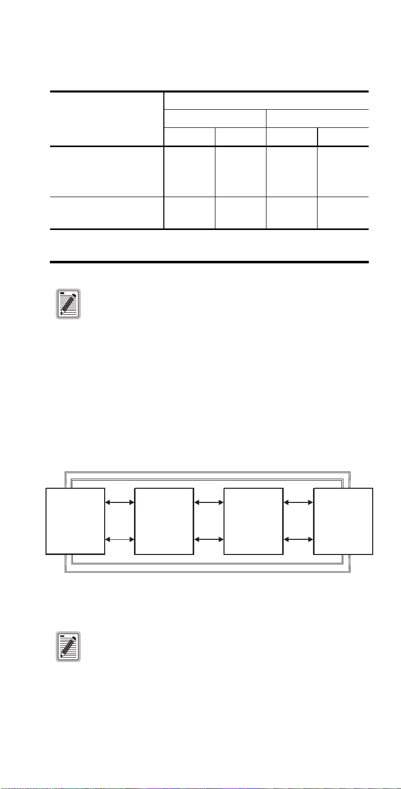
Figure 1 shows a typical HDU-409 List 2 installation for the PG-Flex subscriber carrier
system. For each doubler installed between the PG-Flex Central Office Terminal (COT)
and Remote Terminal (RT), two auxiliary power pairs are required. A maximum of two
doublers may be installed in a PG-Flex system. With two doublers, four sets of auxiliary
power pairs must be installed between the COT and the RT. These auxiliary power pairs
must be the same wire gauge (or lower) as those assigned to the HDSL pairs.
Figure 1. Typical HDU Installation with PG-Flex
DOUBLER DEPLOYMENT
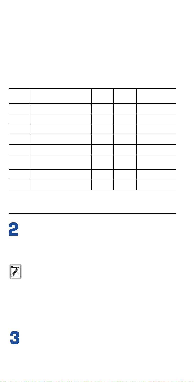
Sealed multislot outdoor enclosures restrict the rate of heat transfer to the outside air. This
restriction may result in excessive heat buildup. Table 2 shows the doubler and repeater
capacities of occupied slots that can be reliably housed in compatible HiGain outdoor
enclosures as a function of solar exposure and maximum ambient temperature. (For a list
of compatible non-ADC enclosures, see the HDU-409 List 1 and List 2 technical practice,
section number 150-409-100-xx.)
The capacities shown in Table 2 can be increased to all odd or even slots (where applicable)
for non-solar load (shaded or manhole applications). For every four T1 repeaters that are
installed with the doublers, the outdoor capacity must be decreased by one doubler or
repeater unit. In addition to the T1 repeaters, the HiGain HDU-439 mini doubler can also
be installed along with the HDU-409 micro doubler in the same enclosure.
INSTALLATION
1Align the HDU-409 with the enclosure slot guides and slide the unit in.
2Push the unit into the enclosure until it snaps into place, indicating that it is properly
seated.
POWER-UPSEQUENCE
Once the HDU-409 is installed in the enclosure, the front panel Status LED flashes green
when power is applied from an upstream unit. Once the loops on both sides of the HDU
synchronize, the LED turns a steady green.
HDSLTipB(in)
HDSLTipA(out)
1
2
3
4
5
6
7
8
9
10
11
12
Ground
Card-edge connector
HDSLTipA(in)
DC(in)test
HDSLRingA(out)
HDSLRingA(in)
DC(out)test
HDSLRingB(in)
HDSLRingB(out)
HDSLTipB(out)
Ground
CLEI/ECI bar
code label
Configuration
number label
(located on top)
Status LED
HDU-409
L
STATUS
List number
Indicates synchronization is being attempted between
the HDU-409 and the upstream module.
Indicates synchronization is being attempted between
the HDU-409 and the downstream module.
Indicates HDSL frame synchronization has been
achieved between the HDU-409 and both the upstream
and downstream modules.
Indicates HDSL Cyclic Redundancy Check (CRC) error
has occured between the HDU-409 and the upstream module.
Indicates HDSL CRC error has occured between the
HDU-409 and the downstream module.
Indicates a loopback at the doubler towards the network.
This loopback tests the integrity of the upstream span(s).
Indicates a loopback at the doubler towards the customer.
This loopback tests the integrity of the downstream span(s).
Indicates the HDSL margin is less than the margin threshold
provisioned for the circuit.
Status LED reports the following conditions:
Flashing green (once per
second)
Flashing green (twice
per second)
Solid green
Flashing red (once per
second)
Flashing red (twice
per second)
Flashing yellow (once per
second)
Flashing yellow (twice
per second)
Solid yellow
Extraction
handle
HiGain
DOUBLER
Table 1. Maximum Number of HDU-409 Doublers per Circuit
HLU Model
Maximum Number of HDU-409 Doublers Per Circuit (a)
(a) The HRU-412 is limited to applications with one and two doublers only.
Line-Powered Remote Locally Powered Remote
I-CPE ON I-CPE OFF I-CPE ON I-CPE OFF
HLU-231 List 3D, List 6D, List 7x
HLU-232 List 1D
HLU-319 List 2x
HLU-388 List 2x,
HLU-431 List 1D
1 2 2 2
HLU-231 List 8x
HLU-319 List 5x
HLU-388 List 5x
23 (b)
(b) Requires HRU-402, all lists.
2 4 (c)
(c) Requires HRU-402 List 1 or List 3.
HiGain systems support doubler loopbacks when HiGain
doublers are used with compatible HiGain circuit modules.
Consult your line unit documentation for details on how to
execute generic or special doubler loopbacks.
PG-Flex systems do not support doubler loopbacks.
PG-Flex
RT
Doubler 1
HDU-409 L2
PG-Flex
COT Span 1
HDSL
Auxiliary Power Pairs
Span 2
HDSL
Doubler 2
HDU-409 L2
Span 3
HDSL
Table 2. Outdoor Enclosure Capacities with Full Solar Load(a)
(a) Maximum sunlight exposure per TR-TSY-000057.
Enclosure
Model Description HDU-409
Doubler
Capacity (b)
(b) Decrease capacities by five-percent (round up) for every 5 °F increase above maximum ambient
temperature. Increase capacities by five percent (round down) for every full 5 °F decrease below maximum
ambient temperature.
239 T1
Repeater
Capacity(b)
Recommended Slot
Assignment for
Maximum Capacity(c)
(c) Refer to the applicable technical practice for full deployment details.
HRE-458 Outdoor canister, pole or wall mount,
with Universal Card Cage 10 10 1-10
HRE-500 Outdoor canister, pole or wall mount,
with Universal Card Cage 11 1
HRE-504 Outdoor canister, pole or wall mount,
with Universal Card Cage 44 1-4
HRE-506 Outdoor canister, pole or wall mount,
with Universal Card Cage 66 1-6
HRE-602 Outdoor canister, pole or wall mount,
with Universal Card Cage 2 2 1 and 2
HRE-712 Outdoor canister, pole mount
(List 1), wall mount (List 2), with
Universal Card Cage 12 12 1-12
HRE-819 Outdoor dual chamber, pole or wall
mount 12 12 1-12
AT&T-819 Outdoor dual chamber pole and wall
mount 14 25 1, 3, 5, 7, 8, 10, 12, 14,
15, 17, 19, 21, 23, 25
The HDU has a Ground Fault Detection (GFD) circuit as described
in R7-1, Section 7.2.1 of GR-1089 CORE, Issue 1, Revision 1,
December 1996.
When used in a HiGain circuit, the HDU-409 immediately detects
ground faults occurring in the span on either side of the interrupted
circuit (doubler) and shuts down the HDSL power feed circuit until the
ground fault is located and repaired. When using older doublers
without a GFD circuit, the HDU-409 must be the doubler nearest the
HLU to support GFD. The ground plane of the doubler enclosure must
be securely connected to earth ground.