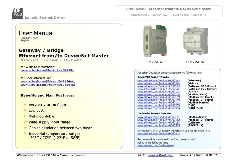
ADF Web HD67412-E Series User manual

Industrial Electronic Devices
ADFweb.com Srl – IT31010 – Mareno – Treviso INFO: www.adfweb.com hone +39.0438.30.91.31
User Manual
CAN f
rom/to Modbus
Slave
Document code: MN67412_ENG Revision 1. Page 1 of 25
User Manual
Revision 1.
English
Gateway
CAN from/to Modbus Slave
(Order Code: HD67412-Exx-xxx)
for Website information:
www.adfweb.com?Product=HD67412
for Price information:
www.adfweb.com?Price=HD67412-E4V
www.adfweb.com?Price=HD67412-E7V
www.adfweb.com?Price=HD67412-E4R
www.adfweb.com?Price=HD67412-E7R
Benefits and Main Features:
Easy to configure
Metal enclosure with fixing lugs
Varnished / Resined (optionally)
Wide supply input range
Triple isolation
Industrial temperature range:
-4 °C / 1 5°C (-22°F / 158°F)
Similiar
Products
For other Gateways / Bridges:
CAN from/to Modbus
See also the following links:
www.adfweb.com?product=HD67411 (Modbus RTU Master)
www.adfweb.com?product=HD67514 (Modbus TCP Master)
www.adfweb.com?product=HD67515 (Modbus TCP Slave)
CANopen from/to Modbus
See also the following links:
www.adfweb.com?product=HD67 1 (Modbus RTU Master)
www.adfweb.com?product=HD675 2 (Modbus RTU Slave)
www.adfweb.com?product=HD675 4 (Modbus TCP Master)
www.adfweb.com?product=HD675 5 (Modbus TCP Slave)
Do you have an your customer protocol?
See the following links:
www.adfweb.com?Product=HD67 3
Do you need to choose a device? do you want help?
Ask it to the following link:
www.adfweb.com?Cmd=helpme

Industrial Electronic Devices
ADFweb.com Srl – IT31010 – Mareno – Treviso INFO: www.adfweb.com hone +39.0438.30.91.31
User Manual
CAN f
rom/to Modbus
Slave
Document code: MN67412_ENG Revision 1. Page 2 of 25
IND X:
Page
INDEX 2
UPDATED DOCUMENTATION 2
REVISION LIST 2
WARNING 2
TRADEMARKS 2
CONNECTION SCHEME 3
POWER SUPPLY 5
RS485 6
CAN 7
CHARACTERISTICS 8
CONFIGURATION 8
USE OF COMPOSITOR SW67412 8
NEW PROJECT / OPEN PROJECT 9
GENERAL PARAMETER 1
RECEIVE COB 11
DEFINE COB 12
TRANSMITCON 13
DEFINE COB 14
UPDATE DEVICE 15
MECHANICAL DIMENSIONS 16
ORDERING INFORMATIONS 2
ACCESSORIES 24
WARRANTIES AND TECHNICAL SUPPORT 25
RETURN POLICY 25
PRODUCTS AND RELATED DOCUMENTS 25
UPDAT D DOCUM NTATION:
Dear customer, we thank you for your attention and we remind you that you
need to check that the following document is:
Updated
Related to the product you own
To obtain the most recently updated document, note the “document code” that
appears at the top right-hand corner of each page of this document.
With this “Document Code” go to web page www.adfweb.com/download/ and
search for the corresponding code on the page. Click on the proper “Document
Code” and download the updates.
To obtain the updated documentation for the product that you own, note the
“Document Code” (Abbreviated written "Doc. Code" on the label on the product)
and download the updated from our web site www.adfweb.com/download/
R VISION LIST:
Revision Date Author Chapter Description
1. 14/11/2 11 Fl All First release version
WARNING:
ADFweb.com reserves the right to change information in this manual about our
product without warning.
ADFweb.com is not responsible for any error this manual may contain.
TRAD MARKS:
All trademarks mentioned in this document belong to their respective owners.

Industrial Electronic Devices
ADFweb.com Srl – IT31010 – Mareno – Treviso INFO: www.adfweb.com hone +39.0438.30.91.31
User Manual
CAN f
rom/to Modbus
Slave
Document code: MN67412_ENG Revision 1. Page 3 of 25
CONN CTION SCH M :
Figure 1-1: Connection scheme for HD67412-E4x-xxx

Industrial Electronic Devices
ADFweb.com Srl – IT31010 – Mareno – Treviso INFO: www.adfweb.com hone +39.0438.30.91.31
User Manual
CAN f
rom/to Modbus
Slave
Document code: MN67412_ENG Revision 1. Page 4 of 25
Figure 1-2: Connection scheme for HD67412-E7x-xxx

Industrial Electronic Devices
ADFweb.com Srl – IT31010 – Mareno – Treviso INFO: www.adfweb.com hone +39.0438.30.91.31
User Manual
CAN f
rom/to Modbus
Slave
Document code: MN67412_ENG Revision 1. Page 5 of 25
POW R SUPPLY:
The devices can be powered between a wide range of tensions. For more details see the
two tables below.
VAC
VDC
Vmin Vmax Vmin Vmax
HD67412- xx-xxx 8V 26V 10V 40V
Consumption at 24V DC:
Device W/VA
HD67412-Exx-xxx 4
Note: It is possible to use also negative tensions. In this case the polarity must be
inverted.
Caution: Not reverse the polarity power
HD67
4
12
-
E4
x
-
xxx
HD67412-E7x-xxx

Industrial Electronic Devices
ADFweb.com Srl – IT31010 – Mareno – Treviso INFO: www.adfweb.com hone +39.0438.30.91.31
User Manual
CAN f
rom/to Modbus
Slave
Document code: MN67412_ENG Revision 1. Page 6 of 25
RS485:
The connection of the RS485 in the HD67 412-E4x-xxx device must be made with a
3way MiniFit Female connector. The pinout of Male MiniFit connector of the board is at
right side of the page.
The connection of the RS485 in the HD67 412-E7x-xxx device must be made with a
AMP SuperSeal 1.5 Male connector. The pinout of Female connector of the board is at
right side of the page.
The termination of RS485 line, with a 22 Ω resistor, in the HD67412-Exx-xxx is made
internally of the device; when the order is performed. If the device have the RS485
terminated the code is the follow: HD67412-Exx-xYx; otherwise is this other: HD67412-
Exx-xNx.
The maximum length of the cable should be 12 m (4 feet).
Here some codes of cables:
Belden: p/n 8132 - 2x 28AWG stranded twisted pairs conductor + foil shield +
braid shield;
Belden p/n 82842 - 2x 24AWG stranded twisted pairs conductor + foil shield +
braid shield;
Tasker: p/n C521 - 1x 24AWG twisted pair conductor + foil shield + braid shield;
Tasker: p/n C522 - 2x 24AWG twisted pairs conductor + foil shield + braid
shield.
Link for Mini-Fit® connectors: http://www.molex.com/molex/products/group?key=minifit_products&channel=products
Link for SuperSeal 1.5 connectors: http://www.te.com/catalog/cinf/en/c/1 876/956

Industrial Electronic Devices
ADFweb.com Srl – IT31010 – Mareno – Treviso INFO: www.adfweb.com hone +39.0438.30.91.31
User Manual
CAN f
rom/to Modbus
Slave
Document code: MN67412_ENG Revision 1. Page 7 of 25
CAN:
The connection of the CAN in the HD67412-E4x-xxx device must be made with a 3way
MiniFit Female connector. The pinout of Male MiniFit connector of the board is at right side
of the page.
The connection of the CAN in the HD67412-E7x-xxx device must be made with a AMP
SuperSeal 1.5 Male connector. The pinout of Female connector of the board is at right side
of the page.
The termination of CAN line, with a 12 Ω resistor, in the HD67412-Exx-xxx is made
internally of the device; when the order is performed. If the device have the CAN
terminated the code is the follow: HD67412-Exx-Yxx; otherwise is this other: HD67412-
Exx-Nxx.
Cable characteristics:
DC parameter: Impedance 7 Ohm/m
AC parameters: Impedance 12 Ohm/m
Delay 5 ns/m
Length Baud Rate [bps] Length MAX [m]
1 K 5
2 K 25
5 K 1
1 K 65
125 K 5
25 K 25
5 K 1
8 K 5
1 K 25

Industrial Electronic Devices
ADFweb.com Srl – IT31010 – Mareno – Treviso INFO: www.adfweb.com hone +39.0438.30.91.31
User Manual
CAN f
rom/to Modbus
Slave
Document code: MN67412_ENG Revision 1. Page 8 of 25
CHARACT RISTICS:
The “CAN from/to Modbus Slave” Gateway has the following characteristics:
Two-directional information between networks CAN and Modbus;
Metal Enclosure with four fixing lugs;
Triple isolation between CAN - Power supply and between CAN – RS485 and between RS485 – Power supply;
Varnished and optionally resined;
Temperature range -4 °C to 1 5°C.
The Gateway can be configured up to a maximum 5 CAN bus frame in reading and 5 CAN bus frame in writing.
Note:
The HD67412-E7x-xxx is furnished with 1 cm cable length.
CONFIGURATION:
The “CAN from/to Modbus Slave” Gateway allows a CAN network to communicate with a Modbus network.
You need Compositor SW67412 software on your PC in order to perform the following:
Define the parameters of two buses;
Define which Modbus Registers are reading from CAN frame;
Define which Modbus Registers are writing from CAN frame;
Update the device.
US OF COMPOSITOR SW67412:
To configure the “CAN from/to Modbus Master” Gateway, use the
available software that runs with Windows, called SW67412. It is
downloadable on the site www.adfweb.com and its operation is
described in this document. (This manual is referenced to the last
version of the software present on our web site). The software works
with MSWindows (MS 2 , XP, Vista, Seven). When launching the
SW67412 the right window appears (Fig. 2).
Figure 2: Main window for SW67412

Industrial Electronic Devices
ADFweb.com Srl – IT31010 – Mareno – Treviso INFO: www.adfweb.com hone +39.0438.30.91.31
User Manual
CAN f
rom/to Modbus
Slave
Document code: MN67412_ENG Revision 1. Page 9 of 25
N W PROJ CT / OP N PROJ CT:
The “New Project” button creates the folder which contains the entire device configuration.
A device configuration can also be imported and exported:
To clone the configurations of a Programmable “CAN from/to Modbus Slave” Gateway in order to configure another device in the same
manner, it is necessary to maintain the folder and all its contents;
To clone a project in order to obtain a different version of the project, it is sufficient to duplicate the project folder with another name
and open the new folder with the button “Open Project”.
When a new project is created or an existent project is open, it will be possible to access the various configuration sections of the software:
“Set Communication”;
“Receive COB”;
“Transmit COB”.

Industrial Electronic Devices
ADFweb.com Srl – IT31010 – Mareno – Treviso INFO: www.adfweb.com hone +39.0438.30.91.31
User Manual
CAN f
rom/to Modbus
Slave
Document code: MN67412_ENG Revision 1. Page 1 of 25
G N RAL PARAM T R:
This section defines the fundamental communication parameters of two buses, CAN and Modbus.
By pressing the “Set Communication” button from the main window for SW67412 (Fig. 2) the window “Set
Communication” appears (Fig. 3).
The window is divided in two sections, one for the CAN and the other for the Modbus line (Serial):
In the field “Baud rate” the velocity of the two buses is defined;
Select the type of CANbus (“CAN Bus 2.0A” or “CAN Bus 2.0B”);
“TimeOut Data” is the maximum time that the device attends for the CAN Frame;
In the field “Modbus Register” insert the value of Modbus register which contains the number 1 if a
CAN frame arrives or the number if it does not arrives before the timeout;
If the field “RS232” is checked the serial line in use is the RS232, otherwise is the “RS485”;
In the field “Parity” the serial parity is defined;
In the field “Dev ID” the Address Device is defined;
If the field “Cancel data after read” is checked, the gateway cancel the data arrived from CAN bus
after a modbus read function
If the field “No Cancel if read Input Reg.” Is checked, the gateway cancel the data arrived from CAN
bus only if you use the Function 3 (Holding Register). If you use teh Function 4 (Input Register) data
will not be cancel.
Figure 3: “Set Communication” window

Industrial Electronic Devices
ADFweb.com Srl – IT31010 – Mareno – Treviso INFO: www.adfweb.com hone +39.0438.30.91.31
User Manual
CAN f
rom/to Modbus
Slave
Document code: MN67412_ENG Revision 1. Page 11 of 25
R C IV COB:
By pressing the “Receive COB” button from the main window for
SW67412 (Fig. 2) the window “Receive CAN Frame” appears (Fig. 4).
A user who has to read a CANbus frame from CANbus to Modbus needs
to insert the coordinates of the CANbus frame in order to be transmitted
in the field “Receive COB” of the window:
In the field “CobID” insert the Cob_ID of the CANbus frame;
In the field “Dimension” insert the number of bytes of the
CANbus frame (the maximum dimension is 8 Bytes);
In the field “Mnemonic” you can insert a brief description.
Figure 4: “Receive CAN Frame” window

Industrial Electronic Devices
ADFweb.com Srl – IT31010 – Mareno – Treviso INFO: www.adfweb.com hone +39.0438.30.91.31
User Manual
CAN f
rom/to Modbus
Slave
Document code: MN67412_ENG Revision 1. Page 12 of 25
D FIN COB:
By pressing the “Define COB” button from the main window for SW67412 (Fig. 2)
the window “Receive CAN Frame Info” appears (Fig. 5):
In the field “COB-ID Frame” there are the COB-ID that you insert in the list
Receive COB;
In the field “MODBUS” there are the modbus words defined for that COB-ID
Frame;
In the field “Index MODBUS” there is the address that contain the Modbus
word;
In the field “Selecet Frame Byte” you select the position of the byte;
For example:
Click on the “COB-ID”, insert the valid address in the field “Index MODBUS”, select
the byte position(B1 in “High MODBUS Byte” and B2 in “Low MODBUS Byte”), click
the “New” button, then in the field “MODBUS” the names of modbus words appear
(The first word is name IND MB , the second IND MB 1, the third Ind MB 2, the
fourth Ind MB 3).
Figure 6:
“Receive CAN Frame Info” window
Figure 5: “Receive CAN Frame Info” window

Industrial Electronic Devices
ADFweb.com Srl – IT31010 – Mareno – Treviso INFO: www.adfweb.com hone +39.0438.30.91.31
User Manual
CAN f
rom/to Modbus
Slave
Document code: MN67412_ENG Revision 1. Page 13 of 25
TRANSMIT COB:
By pressing the “Transmit COB” button from the main window for
SW67412 (Fig. 2) the window “Transmit CAN Frame” appears (Fig. 6).
A user who has to write a CANbus frame from Modbus to CANbus needs
to insert the coordinates of the CANbus frame in order to be transmitted
in the field “Trasmit COB” of the window:
In the field “CobID” insert the Cob_ID of the CANbus frame;
In the field “Dimension” insert the number of bytes of the
CANbus frame (the maximum dimension is 8 Bytes);
In the field “Mnemonic” you can insert a brief description.
Figure 6: “Transmit CAN Frame” window

Industrial Electronic Devices
ADFweb.com Srl – IT31010 – Mareno – Treviso INFO: www.adfweb.com hone +39.0438.30.91.31
User Manual
CAN f
rom/to Modbus
Slave
Document code: MN67412_ENG Revision 1. Page 14 of 25
D FIN COB:
By pressing the “Define COB” button from the main window for SW67412 (Fig. 2)
the window “Transmit CAN Frame Info” appears (Fig. 7).
In the field “COB-ID Frame” there are the COB-ID that you insert in the list;
In the field “MODBUS” there are the Modbus words defined for that COB-ID
Frame;
In the field “Index MODBUS” there is the address that contain the Modbus
word;
In the field “Seleceted Frame Byte” you select the position of the byte.
For example:
Click on the “COB-ID”, insert the valid address in the field “Index MODBUS”, select
the byte position(B1 in “High MODBUS Byte” and B2 in “Low MODBUS Byte”), click
the “New” button, then in the field “MODBUS” the names of modbus words appears
(The first word is name IND MB , the second IND MB 1, the third Ind MB 2, the
fourth Ind MB 3).
Figure 7: “Transmit CAN Frame Info” window

Industrial Electronic Devices
ADFweb.com Srl – IT31010 – Mareno – Treviso INFO: www.adfweb.com hone +39.0438.30.91.31
User Manual
CAN f
rom/to Modbus
Slave
Document code: MN67412_ENG Revision 1. Page 15 of 25
UPDAT D VIC :
By pressing the “Update by CAN” button from the main window for SW67412 (Fig. 2) the right
window appears (Fig. 8).
Note:
For updating the device you need the programmer “AC674 - CAN Interface to configure
devices”.
In order to load the parameters or update the firmware in the gateway, follow these instructions:
Connect the “AC674 ” programmer to the PC through the USB port and connect the CAN
port of the “AC674 ” to the CAN port of HD67412-Exx-xxx;
Select the “COM port” where the “AC674 ” is connected (the USB port of the device is see
like a COM port);
If the BaudRate of CAN is known select it in the field “Select the BaudRate of CAN” otherwise
you have to select “Search Baudrate”;
Press the “Next” button;
Select which operations you want to do. You can select only “Firmware”, only “Project” or
both of them;
Press the “ xecute update firmware” button to start the upload;
When all the operations are “OK” the configuration/firmware on the device is correctly
updated and it is possible to disconnect the “AC674 ” programmer.
Note:
When you install a new version of the software it is better if the first time you do
the update of the Firmware in the HD67412-Exx-xxx device.
Warning:
If the Fig. 9 appears when you try to do the Update before require assistance try these
points:
Check if the serial COM port selected is the correct one;
Check if the CAN cable is connected between the “AC674 ” and the device;
Try to repeat the operations for the updating;
Try with another PC;
Try to restart the PC.
Figure
8
:
“
Update Device
” windows
Figure 9: “ rotection” window

Industrial Electronic Devices
ADFweb.com Srl – IT31010 – Mareno – Treviso INFO: www.adfweb.com hone +39.0438.30.91.31
User Manual
CAN f
rom/to Modbus
Slave
Document code: MN67412_ENG Revision 1. Page 16 of 25
M CHANICAL DIM NSIONS:

Industrial Electronic Devices
ADFweb.com Srl – IT31010 – Mareno – Treviso INFO: www.adfweb.com hone +39.0438.30.91.31
User Manual
CAN f
rom/to Modbus
Slave
Document code: MN67412_ENG Revision 1. Page 17 of 25
Type A

Industrial Electronic Devices
ADFweb.com Srl – IT31010 – Mareno – Treviso INFO: www.adfweb.com hone +39.0438.30.91.31
User Manual
CAN f
rom/to Modbus
Slave
Document code: MN67412_ENG Revision 1. Page 18 of 25
Type
B

Industrial Electronic Devices
ADFweb.com Srl – IT31010 – Mareno – Treviso INFO: www.adfweb.com hone +39.0438.30.91.31
User Manual
CAN f
rom/to Modbus
Slave
Document code: MN67412_ENG Revision 1. Page 19 of 25
Type C

Industrial Electronic Devices
ADFweb.com Srl – IT31010 – Mareno – Treviso INFO: www.adfweb.com hone +39.0438.30.91.31
User Manual
CAN f
rom/to Modbus
Slave
Document code: MN67412_ENG Revision 1. Page 2 of 25
ORD RING INFORMATIONS:
The ordering part number is formed by a valid combination of the following:
HD67412 – y z – s d f
Fixing lugs
A: Type 1
B: Type 2
C: Type 3
RS485 Termination
Y = Terminated with 22 Ω
N = Not terminated
CAN Termination
Y = Terminated with 12 Ω
N = Not terminated
Varnished/Resinated
V = Varnished
R = Resined
Connectors Type
4 = MiniFit
7 = SuperSeal 1.5
nclosure Type
E: Metal enclosure
Device Family
HD67412 = CAN from/to Modbus Slave
Table of contents
Other ADF Web Gateway manuals
Popular Gateway manuals by other brands

ICC
ICC ETH-1000 Quick installation guide

Screen Innovations
Screen Innovations LinkPro installation instructions

IPTC
IPTC Albatross DEX28-GE2P Quick installation guide
ZyXEL Communications
ZyXEL Communications AMG1202-T series quick start guide
TVILIGHT
TVILIGHT TVI-GW-1 Series installation manual
SoluM
SoluM ESL SLG-CP101 user manual
