Nice WMS01S Product manual

EN - Installation and use instructions and warnings
IT - Istruzioni ed avvertenze per l’installazione e l’uso
FR - Instructions et avertissements pour l’installation et l’utilisation
ES - Instrucciones y advertencias para la instalación y el uso
DE - Anweisungen und Hinweise für die Installation und die Bedienung
PL - Instrukcje instalacji i użytkowania i ostrzeżeni
NL - Aanwijzingen en aanbevelingen voor installering en gebruik
WMS01S
0682
Transmitter

NL PL DE ES FR IT EN
EN QUICK GUIDE FOR GETTING TO
KNOW THE PRODUCT
Fig. A – Recommendations for installation.
Fig. B – Two installation possibilities.
Fig. C – Optional supports for installation in “Scenario B”.
Fig. D – Transmitter switch-on/off.
Fig. E – User screen. It is shown when the display is
switched-on.
Fig. F – Programming screen.
Fig. G – System functioning in “Modality 1” (for scenario
type A).
Fig. H – System functioning in “Modality 2” (for scenario
type A).
Fig. I – System functioning in “Modality 3” (for scenario
type B).
IT
GUIDA RAPIDA PER CONOSCERE
IL PRODOTTO
Fig. A – Avvertenze per l’installazione.
Fig. B – Due possibilità di installazione.
Fig. C – Supporti opzionali per l’installazione nello “Sce-
nario B”.
Fig. D – Accensione/spegnimento del trasmettitore.
Fig. E – Schermata utente. Viene mostrata all’accensione
del display.
Fig. F – Schermate per la programmazione.
Fig. G – Funzionamento del sistema in “Modalità 1” (per lo
scenario di tipo A).
Fig. H – Funzionamento del sistema in “Modalità 2” (per lo
scenario di tipo A).
Fig. I – Funzionamento del sistema in “Modalità 3” (per lo
scenario di tipo B).
FR GUIDE RAPIDE POUR
CONNAÎTRE LE PRODUIT
Fig. A – Avertissements pour l’installation.
Fig. B – Deux possibilités d'installation.
Fig. C – Supports optionnels pour l’installation dans le
cas du « Scénario B ».
Fig. D – Allumage/Arrêt de l'émetteur.
Fig. E – Écran Utilisateur. S'affiche à l'allumage de l'affi-
cheur.
Fig. F – Écrans pour la programmation.
Fig. G – Fonctionnement du système en « Mode 1 » (pour
le scénario de type A).
Fig. H – Fonctionnement du système en « Mode 2 » (pour
le scénario de type A).
Fig. I – Fonctionnement du système en « Mode 3 » (pour
le scénario de type B).
ES GUÍA RÁPIDA PARA CONOCER
EL PRODUCTO
Fig. A – Advertencias para la instalación.
Fig. B – Dos posibilidades de instalación.
Fig. C – Ayudas opcionales para la instalación en el
“Escenario B”.
Fig. D – Encendido/apagado del transmisor.
Fig. E – Esquema usuario. Se muestra en el encendido
de la pantalla.
Fig. F – Pantalla para la programación.
Fig. G – Funcionamiento del sistema en “Modo 1” (para el
escenario de tipo A).
Fig. H – Funcionamiento del sistema en “Modo 2” (para el
escenario de tipo A).
Fig. I – Funcionamiento del sistema en “Modo 3” (para el
escenario de tipo B).
DE
KURZANLEITUNG ZUM KENNEN-
LERNEN DES PRODUKTS
Abb. A –
Installationshinweise.
Abb. B –
Zwei Installationsmöglichkeiten.
Abb. C –
Optionale Halterungen für die Installation in „Sze-
nario B“.
Abb. D –
Ein-/Ausschalten des Senders.
Abb. E –
Benutzerbildschirm. Wird beim Einschalten des
Displays angezeigt.
Abb. F –
Bildschirmseiten für die Programmierung.
Abb. G –
Funktionsweise des Systems in „Vorgehenswei-
se 1“ (für ein Szenario vom Typ A).
Abb. H –
Funktionsweise des Systems in „Vorgehenswei-
se 2“ (für ein Szenario vom Typ A).
Abb. I –
Funktionsweise des Systems in „Vorgehenswei-
se 3“ (für ein Szenario vom Typ B).
PL SZYBKA INSTRUKCJA DO
ZAPOZNANIA SIĘ Z PRODUK-
TEM
Rys. A –Uwagi dotyczące montażu.
Rys. B –Dwie możliwości montażu.
Rys. C –Podpórki opcyjne do montażu w „Wersji B”.
Rys. D –Włączenie/wyłączenie nadajnika.
Rys. E – Ekran użytkownika. Pojawia się podczas włącza-
nia wyświetlacza.
Rys. F – Ekrany do programowania.
Rys. G –Funkcjonowanie systemu w „Trybie 1” (dla wersji
typu A).
Rys. H –Funkcjonowanie systemu w „Trybie 2” (dla wersji
typu A).
Rys. I – Funkcjonowanie systemu w „Trybie 3” (dla wersji
typu B).
NL SNELGIDS OM HET PRODUCT
TE LEREN KENNEN
Afb. A – Waarschuwingen voor de installatie.
Afb. B – Twee installatiemogelijkheden.
Afb. C – Optionele houders voor de installatie in “Configu-
ratie B”.
Afb. D – Inschakeling/uitschakeling van de zender.
Afb. E – Gebruikersbeeldscherm. Wordt getoond bij
inschakeling van het display.
Afb. F – Beeldschermen voor de programmering.
Afb. G – Werking van het systeem in “Modaliteit 1” (voor
configuratie type A).
Afb. H – Werking van het systeem in “Modaliteit 2” (voor
configuratie type A).
Afb. I – Werking van het systeem in “Modaliteit 3” (voor
configuratie type B).

A
scenario “A”
scenario “A”
scénario « A»
escenario “A”
Szenario „A“
wersja „A”
configuratie “A”
scenario “B”
scenario “B”
scénario « B»
escenario “B”
Szenario „B“
wersja „B”
configuratie “B”
B
C
Stone Ondo Opla
D
Intensity
Light Set
E

Testing
Menu block
Disabled
Enabled
Modality
Modality 1
Modality 2
Modality 3
Presentation
Active
Not active
Reset defaults
Dont reset
Reset to defaults
Languages
English
Italiano
Français
Min/max
Light set
Min/max
Light set
Intensity
Light Set
(2 sec.)
Timed pause
Mins 10
Hours 00
Days 00
F

G I
H


English – 1
EN
14 5
32
1
oda n m l
bc
fh
gi
h
e
2
ENGLISH
–– FIRST PART ––
for the user and installer
1 - Recommendations regarding safety
(fig. A)
Only install the product in indoor or protected environ-
ments. Do not wet the product with liquid substances and
keep it away from steam and excessive humidity.
2 - Description of the product and
destination of use
WMS01S is a radio transmitter that allows to control the Nice
automations for shutters, sun screens and sun awnings, in
manual mode or in automatic mode.
The main purpose of the product is to be used in automat-
ic mode, to control the comfort of the indoor environment
through opening and closing of the sun screens, protecting
it from excessive sunlight.
In order to function in automatic mode, the product makes
use of light sensors, one rear and one front, which allow to
control the sun screens depending on the intensity of the
sunlight.
The rear sensor only allows to control the shutters on the
window where the transmitter is installed.
However, the front sensor allows to control various types of
sun screens such as shutters, sun awnings and similar. In
this case, the transmitter must be installed inside the envi-
ronment to be protected, in a position where it can perceive
the effects of the greater or lesser sun screening, without
however being hit directly by the light coming from outdoors.
All other use is prohibited! The manufacturer declines all
responsibility for damage/injury caused to objects/per-
sons deriving from improper use of the product, differ-
ent to that described in this manual.
2.1 - Parts of the product (fig. 1)
1) - Data display.
2) - Keys with various functions (see chapter 5).
3) - Front light sensor.
4) - Rear light sensor.
5) - Battery compartment.
3 - Display switch-on/off
The display switches-on by pressing any key and switch-
es-off automatically after 30 seconds from when the last
key is pressed.
4 - The product screens
4.1 - The user screen (fig. 2)
On display switch-on, the user screen appears, made up
from the following elements:
a) “Intensity” Bar: shows the intensity of the light cap-
tured by the sensor.
b) Minimum light value (total darkness).
c) Maximum light value (blinding sun).
d) Light intensity value measured in real time.
e) “Light set” Bar: shows the points in which the interven-
tion thresholds are positioned and the amplitude of the
hysteresis area.
f) UPPER threshold (corresponds to the right end of the cur-
sor): when the light intensity increases and exceeds this
threshold, the system automatically controls the move-
ment of the sun screen with the purpose of decreasing the
light in the environment.
g) LOWER threshold (corresponds to the left end of the
cursor): when the light intensity decreases and exceeds
this threshold, the system automatically controls the
movement of the sun screen with the purpose of
increasing the light in the environment.
h) Minimum and maximum limit (not visible) within which it
is possible to shift the cursor-thresholds.
i) hysteresis area: it is the space between the two thres-
holds.
l) Symbol: appears when the battery is running out.
m) Symbol: appears when access to the programming
environment is blocked.
n)
Symbol: appears when the transmitter is in “Manual
pause”.
o) Symbol: appears when the transmitter is in “Timed
pause”.
4.2 - The programming screens
The programming environment is formed by several screens.
To access the first screen, with the display on, hold the °key
down until the icons appear and then release the key. To
operate in the programming environment, refer to chapter 10.

2– English
EN
7 - Installation and functioning of the
product
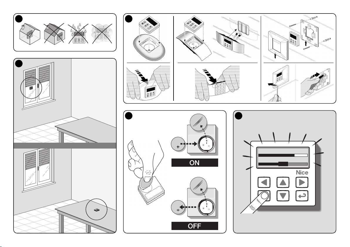
The product can be installed in two different scenarios
(fig. 3). The elements that make up these scenarios are:
– scenario A
• control of shutters or screens outside of the glass;
• installing the transmitter on the glass of the correspon-
ding window, at the desired height.
• using the rear sensor.
–scenario B
• command to control shutters, sun screens and sun
awnings;
• installing the transmitter on any surface (table, cabinet,
etc.), in any point of the environment in a position that
allows it to perceive the effects of the greater or less sun
screening, without however being hit by the direct light
coming from outdoors.
• using the front sensor.
7.1 - Scenario “A”
7.1.1 - Installation
Install the transmitter by fixing it, only with the appropriate
suction device, to any point on the window, with the display
facing inwards.
Before attaching the suction device, clean the glass and
wet the suction disc with water so that it can stick perfectly
to the glass. Attention! - The point where the transmitter is
fixed to the glass determines the height at which the shut-
ter will stop during the closure manoeuvre (fig. 4).
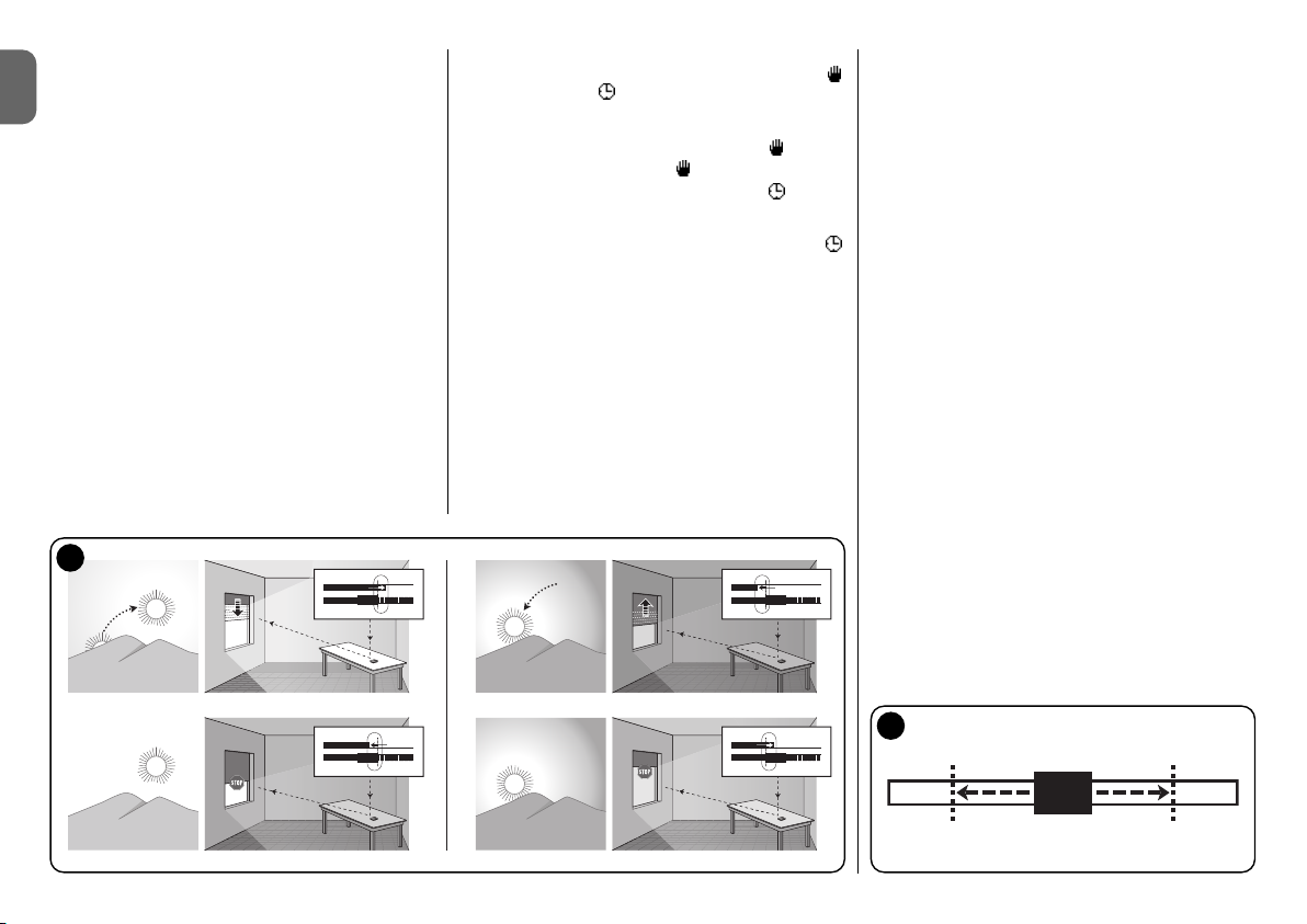
7.1.2 - Functioning
When the transmitter is installed in scenario “A”, the
“Modality” function must be programmed (see chapter 10)
selecting one of the following options.
• “Modality 1” – (fig. 5) With the shutter open and the sen-
sor exposed to the light, when the light intensity increases
and exceeds the Upper threshold, after 4 minutes the shutter
lowers to the sensor and returns up by a few centimetres,
leaving the sensor exposed to the light
(partial closure).
Successively, when the light intensity decreases and exce-
eds the Lower threshold, after 15 minutes the shutter rises
completely (total opening).
The user can move the shutter as desired at any time,
using the p, ■, qkeys.
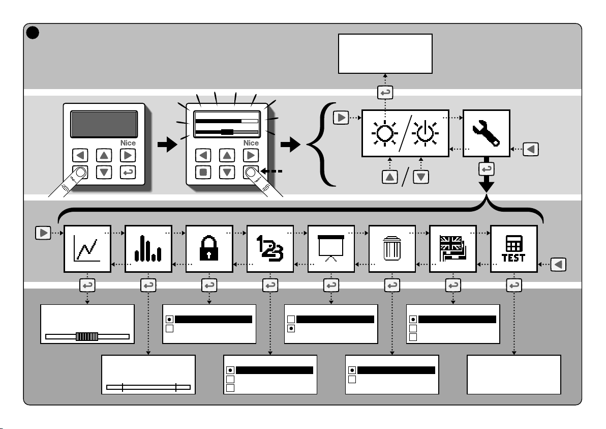
5 - Specific functions of the keys
5.1 - in the user environment
tKey to pause the system/to select the cursor-
thresholds.
uKey not active in this environment.
pq■Keys for manual control of ascent, descent,
stop.
°Key for access to the programming environ-
ment/to confirm the selection in a sub-menu/to
memorise the value or option programmed.
u+ °Keys for releasing the programming environ-
ment when it is blocked (to be pressed simulta-
neously for a few seconds).
5.2 - in the programming environment
tu Keys for horizontal shifting, between the menus
and sub menus.
pq Keys for shifting vertically among the menu items/to
increase or decrease the values/to change the
options.
■Key for returning to the previous screen or menu,
without memorising any modifications made.
°Key for confirming the selection of a sub-menu/to
memorise the value or the option programmed
and return to the previous screen at the same
time.
6 -
Memorising the code in the receiver
Attention! – The transmitter is only compatible with the
radio receivers that operate at the frequency of 433.92
MHz and that uses the radio code “Flo-R”.
To memorise, use the “Mode I” procedure described in the
tubular motor manual or that of the associated receiver. The
manual is also present in the site www.nice-service.com.
Without this manual, it is also possible to use one of the fol-
lowing procedures.
PROCEDURE “A”
Memorising the first transmitter
Only use this procedure if no other transmitter is memori-
sed in the tubular motor.
01. Disconnect and re-connect the tubular motor to the
power supply: the motor emits 2 long sounds (or 2
long movements). Attention! - If on switch-on the
motor emits 2 brief sounds (or 2 short movements,
or no movement) it means that other transmitter
codes are memorised. Therefore interrupt the pro-
cedure and use "Procedure B”.
02. With the display on, within 5 seconds hold the ■key
of the transmitter down and then release it after the
motor has emitted the first of the 3 brief sounds (or the
first of the 3 short movements) that signal that memo-
risation has taken place.
PROCEDURE “B”
Memorising further transmitters
Only use this procedure if one or more transmitters are
already memorised in the tubular motor.
01. (on this transmitter) With the display on, hold the ■
key down until the motor emits 1 long sound.
02. (on a transmitter already memorised) Press the ■key
slowly 3 times.
03. (on this transmitter) With the display on, press the ■
key once.
04. The motor emits 3 brief sounds (or 3 long movements)
to indicate memorisation.
Note – If the motor emits 6 brief sounds (or 6 long move-
ments) it means that the memory is full.

English – 3
EN
4
5
3scenario “A”
scenario “B”
6
If the user controls opening, when the light successi-
vely decreases and exceeds the Lower threshold, the
system does not move the shutter.
If, however, the user controls closure, which prevents
the direct action of the light on the sensor, the system
interrupts its automatic functioning. To restore it, the
user must intervene by re-opening the shutter in order
to expose the sensor to direct sunlight again.
• “Modality 2” – (fig. 6) This modality is similar to “Modali-
ty 1”, with the difference that when the light intensity
decreases and exceeds the Lower threshold, the system
does not move the shutter (it leaves it where it is). In con-
clusion, the system only closes the shutter to the point in
which the transmitter is positioned and any opening mano-
euvres must be made by the user.
Note - The product is set-up in the factory to be installed
un scenario “A” and functioning is set-up in “Modality 1”.
7.2 - Scenario “B”
7.2.1 - Installation
Install the transmitter inside the room with the sun scree-
ning to be moved. The transmitter can be placed freely on
any surface (table, cabinet or other) or fixed to the same
using the relevant suction device. Moreover, it can be inser-
ted in other optional supports, as shown in fig. C.
7.2.2 - Functioning
When the transmitter is installed in scenario “B”, the
“Modality” function must be programmed (see chapter 10)
selecting the following option.
• “Modality 3” – (fig. 7) This option activates the front sen-
sor. Make partial movements opening and closure move-
ments of the sun screen, with the purpose of maintaining
(within the limits made up by the Lower and Upper thre-
sholds) the light level constant inside the environment.
The functioning is the following: with the sun screen com-
pletely open, when the light intensity increases and exce-
eds the Upper threshold, the sun screen starts to close
and only stops when the light returns back within the
hysteresis zone.
In the same way, when the light intensity decreases and
exceeds the Lower threshold, the sun screening starts to
open and only stops when the light returns back within the
hysteresis zone.

4– English
EN
8
7
The user can take the sun screen to a desired position
at any time, using the p, ■, qkeys and can pause the
system (paragraph 8.1).
8 - Controls and settings that can be
modified by the user
8.1 - “Pause” Function
This function allows to temporarily suspend the automatic
functioning of the system. It is useful to prevent the shutter
from moving autonomously during maintenance of the
automation, when cleaning the glass, watering plants on
the window ledge etc.
The function can be customised within the programming
environment by setting the “Manual pause” or “Timed pause”
option. For the latter it is also possible to set a desired pause
value (minimum 10 minutes). To activate or deactivate the
pause in the user screen, proceed as follows:
- Activate Pause:
(with display on) Hold the tkey down until the
(manual pause) or (timed pause) symbol appears
on the display.
- Deactivate Pause:
• (with display on) If the display shows the symbol,
hold the tkey down until the symbol disappears.
• (with display on) If the display shows the symbol,
deactivation takes place automatically when the time
programmed by the installer expires. If the pause is to be
activated in advance, hold the tkey down until the
symbol disappears from the display.
8.2 - Regulation of the position of the cursor-
thresholds (fig. 8)
The user can shift the cursor-threshold along the “Light
set” bar, within the limits pre-set by the installer, positioning
it in correspondence of desired light values. Proceed as fol-
lows to move the cursor:
01. With the display on, briefly press the tkey: the cur-
sor-thresholds starts to flash.
02. If the level is to be increased, hold the pkey down or
if the level is to be decreases, hold the qkey down.
03. Finally, press the °key to memorise the new position
and go back to the user screen.
If the regulation made does not have to be memorised,
wait for the display to switch off or press the ■key.

English – 5
EN
–– SECOND PART ––
for the installer
9 - Programming the functions
The adjustable functions and settings allow to customise
the functioning of the product, adapting it to the scenario in
which it is installed and customer requirements.
8.1 - Access to the programming environment
01. Switch the display on by pressing any key: the user
screen will appear.
02. Hold the °key down until the icons appear and then
release the key.
The programming environment is formed by various scre-
ens with menus, sub-menus, options and values that can
be modified (settings). To navigate among these elements,
refer to chapter 5 and fig. F.
10 - Programmable functions and
settings
PAUSE function
This function is used to deactivate sending
the commands to the automation automati-
cally. To use it, read paragraph 8.1.
The programming allows to select one of the following fun-
ctioning modalities:
-“Manual pause” - this modality envisions the activation
and the manual deactivation of the pause by the user.
To set the modality, select the function icon using the q
key and confirm using the °key.
-
“Timed pause” - this modality envisions the manual acti-
vation of the pause by the user and the automatic deacti-
vation, when the programmed stand-by time has expired.
Proceed as follows to set this modality:
01. Select the function icon using the pkey and confirm
using the °key.
02. Set the desired time in the screen that appears (mini-
mum value = 10 minutes): scroll the list (minutes,
hours, days) using the tand ukeys and regulate the
value using the pand qkeys.
03. Finally, press the °key to memorise the new value.
SETTINGS menu
After having selected the “Settings” icon and having confir-
med using the °key, a sub-menu appears with the follo-
wing functions.
• “Hysteresis”
This function allows to increase or decrease the
space between the Lower and Upper threshold.
The greater or smaller width of the hysteresis determines
the frequency with which the system moves the sun scre-
en: the narrower this space, the greater the frequency with
which the sun screen is moved, as the system tends to
react also with small light variations such as, for example,
those determined by a passing cloud. Vice versa, the wider
the hysteresis space, the lower the frequency with which
the sun screen is moved as, in this case, the system reacts
only to significant light variations. It is therefore recommen-
ded to regulate the hysteresis space on values suitable for
the user's requirements.
• “Min/Max”
This function allows to regulate the minimum and
maximum light limit on the “Light set” bar, within
which the user can shift the cursor-thresholds. Generally,
consider that the greater the distance between the two
limits the greater the probability that the user can jeopardi-
se the correct functioning of the system, by shifting the
cursor-thresholds onto values that have light values that
are too high or too low.
• “Modality”
This function allows to set the functioning modality
of the product, according to scenario “A” or “B”
described in chapter 7.
The “Modality 1” and “Modality 2” options activate functio-
ning of the rear sensor, while the “Modality 3” option activa-
tes the front sensor.
• “Reset defaults”
ATTENTION! - The operation cancels all of
the settings programmed by the installer
and restores the values and options set in the fac-
tory.
• “Menu block”
This function allows to prevent user access to the
programming environment.
- To block programming:
01. Select the “Settings” menu and confirm using the °
key.
02. From the sub-menu, select the “Menu block” function
and confirm with the °key.
03. In the screen that appears, use the pand qkeys to
select the “Enabled” option and confirm using the °
key.
When programming is blocked, the symbol appears in
the user screen.
- To release programming:
01. If the display is off, switch it on by pressing any key.
02. The user screen appears.
03. Hold down the uand °keys simultaneously until a
screen appears with the programming icons and then
release the two keys.
• “Presentation”
This function simultaneously activates the “infor-
mation” and the “demonstration” screens. This are
disabled automatically after 15 minutes.
- “Information” screen: this screen displays the product
identification data. When the “Presentation” function is
active, the screen appears briefly every time the display is
switched-on.
- “Demonstration” function: this function accelerates the
product functioning times, where every second corre-
sponds to a minute in normal mode. The function is use-
ful during programming as it allows to simulate and quic-
kly understand how the product behaves on light varia-
tions, preventing long waits.

6– English
EN
What to do if...
(troubleshooting)
9
• “Language”
This function allows to select the language of the
display texts.
To set a language, select the “Settings” menu and confirm
with the °key. From the sub-menu, select the “Language”
function and confirm using the °key. In the screen that
appears, use the pand qkeys to select the desired lan-
guage and confirm using the °key.
• “Test”
Se the "What to do if..." chapter.
• If the shutter does not move during the day and the
symbol is present on the display.
Replace the battery.
• If the display does not switch-on when any key is
pressed.
Try and replace the battery (fig. 9).
• If the shutter does not move during the day.
Check with different light conditions (from dawn to dusk)
whether the light value given in the “Intensity” bar exceeds
the intervention thresholds in the “Light set” bar and, as a
consequence, whether the system moves the shutter. If
this does not take place, try and move the cursor-thre-
sholds into a new position (paragraph 8.2).
• If the shutter moves too often during the day.
Try and modify the hysteresis space by referring to the
description given in chapter 10 (“Hysteresis” function).
• If a test is to be performed on parts of the product, to
check their regular functioning.
Enter the “Settings” menu, select the “Test” function and
confirm with the °key.
At this point it is possible to perform the following tests:
a) identification of the keys: by pressing each individual
key, the code appears that identifies the key pressed
(example: t= key = code “P1”; p= key code “P2”;
etc.).
b) check the display: hold the tkey down until the
display is all black (this is used to check the state of the
pixel matrix). Then, pressing the key again, “1 2 3” will
appear. Pressing a third time all of the characters used on
the display appear and a fourth press makes the display
appear all black again.
Press the °key to exit this test.
c) check the light sensors: hold the ■key down until the
“Intensity Rear” bar appears on the display. By pressing
the key a second time the “Intensity Front” bar appears
(used to check correct functioning of the light sensors).
Press the °key to exit this test.
d) prolonged transmission of the “STOP” control:
hold the qkey down until “STOP” appears on the
display and then release the key: the transmitter starts to
transmit the Stop command continuously. To interrupt
transmission, press the same key again (useful function
for carrying out radio transmission tests).
Press the °key to exit this test.
To exit the “Test” function definitively, hold the °key down
until the display shows the screen with 3 icons from the
1st level.

English – 7
EN
Product maintenance
and disposal
10
11 - Cleaning the product
Clean the product using a soft, damp cloth, preventing
water seeping into the product. Do not use other liquid
substances such as detergents, solvents and similar.
12 - Changing the battery
appears on the display when the battery is flat. There-
fore, replace the battery as shown in fig. 9, using another
of the same type (read the “Technical features” paragraph).
Respect the polarity indicated.
13 - Product disposal
• Battery
Attention! – The product contains a battery, which must
be removed if the product is disposed off. Even if the batte-
ry is flat it contains pollutants that make it mandatory for
the user to dispose of it according to the methods envisio-
ned by local regulations regarding “separate collection”:
generally, waste batteries can be deposited in the relevant
containers made available by the distribution network. In all
cases, it is prohibited to throw the batteries into the house-
hold waste (fig. 10).
Attention! – If substances should escape from the battery,
protect the hands with suitable gloves, to prevent injury.
• Product
This product is an integral part of the automation and
therefore must be demolished with it.
As for installation, the plant must also be demolished by
qualified staff at the end of its life span.
This product is made up of various types of materials:
some can be re-cycled, others must be disposed of.
Obtain information regarding recycling or disposal systems
envisioned by the Standards in force on your territory for
this category of product.
Attention! – some parts of the product can contain pollu-
tant or dangerous substances which, if dispersed into the
environment, could have damaging effects on the same
and human health.
As indicated by fig. 10, it is prohibited to throw this product
into domestic waste. “Separate collection” must be perfor-
med for disposal, according to the methods envisioned by
the Regulations in force on your territory or take the pro-
duct back to your dealer on the purchase of a new equiva-
lent product.
Attention! – local regulations in force may envision heavy
sanctions if this product is disposed of abusively.
TECHNICAL FEATURES
•Power supply: CR2032 3Vdc lithium battery
•Battery duration: estimated at over 1 year, considering
2 switch-ons and the transmission of 10 controls per
day
•Transmission frequency: 433.92 MHz (±100 KHz)
•Capacity: estimated, up to 200 m in open range or
35 m inside buildings
•Irradiated power: estimated about 1 mW e.r.p.
•Radio code: 52 bit; rolling code type; Flo-R code
•Light sensors: 2 logarithmic type sensors: 1 front and
1 rear
•Light measurement: values between 50 lx and 50 Klx,
with resolution of 8 bit
•Sampling: frequency of 1 detection every minute
•Display: monochromatic LCD; measurement 33 x
13 mm, 128 x 49 pixels; graphical interface with icon
menu
•Functioning temp.: from -20°C to +55°C
•Protection rating: IP 40 (use in the home or protected
environments)
•Dimensions: L. 41 x P. 41 x H. 12 mm
•Weight: 18 g
Notes:
– The capacity of the transmitters and the reception capacity of
the receivers is greatly affected by other devices (for example:
alarms, radio ear-pieces, etc.) that operate your area at the
same frequency. In these cases, the manufacturer cannot
offer any guarantee regarding the real capacity of its own
devices.
– All technical features stated make reference at a room tempe-
rature of 20°C (± 5°C).
– Nice S.p.a. reserves the right to modify the product at any
time it deems necessary, however maintaining the same fun-
ctionalities of the same.

8– English
EN
CE DECLARATION OF CONFORMITY
Note - The content of this declaration corresponds with that declared in the latest revision available, before printing this manual, of the
official document deposited in the Nice Spa. head offices. This text has been re-adapted for editorial reasons.
Number: 326/WMS01S Revision: 0
The undersigned Luigi Paro in the quality of Managing Director, declares under his own liability that the product:
Manufacturer's name: NICE s.p.a.
Address: Via Pezza Alta, 13, Z.I. Rustignè, 31046 - Oderzo (TV) Italia
Type: 433.92MHz transmitter for long distance control of automations for sun awnings, shutters and sun screens
Models: WMS01S
Accessories: –––
results in compliance with the essential requisites requested by article 3 of the following European Community
Directive, for the use for which the products are intended:
• 1999/5/CE DIRECTIVE 1999/5/CE OF THE EUROPEAN PARLIAMENT AND COUNCIL dated 9 March 1999
regarding radio and telecommunications terminal equipment and the reciprocal recognition of their conformity
according to the following Harmonised Standards:
- health protection: EN 50371:2002;
- electric safety: EN 60950-1:2006;
- electromagnetic compatibility: EN 301 489-1V1.8.1:2008; EN 301 489-3V1.4.1:2002
- radio spectrum: EN 300220-2V2.1.2:2007
In compliance with the 199/5/CE Directive (attachment V), the product results as class 1 and marked:
Oderzo, 04.08.09
Luigi Paro
(Managing Director)
0682

Italiano – 1
IT
1 - Avvertenze per la sicurezza (fig. A)
Installare il prodotto esclusivamente in ambienti interni o
protetti. Non bagnare il prodotto con sostanze liquide e
tenerlo lontano dal vapore e dall’umidità eccessiva.
2 - Descrizione del prodotto e destina-
zione d’uso
WMS01S è un trasmettitore radio che permette di coman-
dare gli automatismi Nice per tapparelle, schermi solari e
tende da sole, in modo manuale o in modo automatico.
Lo scopo principale del prodotto è quello di essere utilizza-
to in modo automatico, per controllare attraverso l’apertura
e la chiusura della schermatura solare, il comfort dell’am-
biente interno, proteggendolo dal sole eccessivo.
Per funzionare in modo automatico il prodotto sfrutta due
sensori luce, uno posteriore e uno anteriore, che gli per-
mettono di comandare la schermatura solare in funzione
dell’intensità della luce solare.
Il sensore posteriore consente di comandare solo la tappa-
rella abbinata alla finestra sul cui vetro è installato il tra-
smettitore.
Invece, il sensore anteriore consente di comandare varie
tipologie di schermature solari come tapparelle, tende da
sole e similari. In questo caso il trasmettitore si installa
all’interno dell’ambiente da proteggere, in una posizione
dove possa percepire gli effetti della maggiore o minore
schermatura solare, senza però essere colpito direttamen-
te dalla luce proveniente dall’esterno.
Ogni altro uso è vietato! Il costruttore declina ogni
responsabilità per danni a cose o a persone derivanti
da un uso improprio del prodotto, diverso da quello
descritto in questo manuale.
2.1 - Parti del prodotto (fig. 1)
1) - Display per la visualizzazione dei dati.
2) - Tasti con varie funzioni (vedere il capitolo 5).
3) - Sensore luce frontale.
4) - Sensore luce posteriore.
5) - Vano per l’alloggiamento della batteria.
3 - Accensione e spegnimento del
display
Il display si accende premendo un tasto qualsiasi e si spe-
gne automaticamente dopo circa 30 secondi dall’ultimo
tasto premuto.
4 - Le schermate del prodotto
4.1 - La schermata utente (fig. 2)
All’accensione del display appare la schermata utente for-
mata dai seguenti elementi:
a) Barra “Intensità”: mostra l’intensità della luce captata
dal sensore.
b) Valore minimo di luce (buio totale).
c) Valore massimo di luce (sole accecante).
d) Valore dell’intensità luminosa misurata in tempo reale.
e) Barra “Taratura luce”: mostra i punti in cui sono posi-
zionate le soglie di intervento e l’ampiezza della zona di
isteresi.
f) Soglia SUPERIORE (corrisponde all’estremità destra
del cursore): quando l'intensità luminosa aumenta e
supera questa soglia, il sistema comanda automatica-
mente il movimento della schermatura solare allo scopo
di diminuire la luce nell’ambiente.
g) Soglia INFERIORE (corrisponde all’estremità sinistra del
cursore): quando l'intensità luminosa diminuisce e
supera questa soglia, il sistema comanda automatica-
mente il movimento della schermatura solare allo scopo
di aumentare la luce nell’ambiente.
h) Limite minimo e massimo (non visibili) entro cui è possi-
bile spostare il cursore-soglie.
i) zona di isteresi: è lo spazio tra le due soglie.
l) Simbolo : appare quando la batteria si sta esau-
rendo.
m)
Simbolo : appare quando è bloccato l’accesso all’am-
biente programmazione.
n)
Simbolo : appare quando il trasmettitore è in “Pausa
manuale”.
14 5
32
1
ITALIANO
–– PRIMA PARTE ––
per l’utente e l’installatore
Istruzioni originali
o)
Simbolo : appare quando il trasmettitore è in “Pausa
temporizzata”.
4.2 - Le schermate per la programmazione
L’ambiente programmazione è formato da più schermate.
Per accedere alla prima schermata, con il display acceso,
mantenere premuto il tasto °fino a quando appaiono del-
le icone; quindi, rilasciare il tasto. Per operare nell’ambien-
te programmazione fare riferimento al capitolo 10.
oda n m l
bc
fh
gi
h
e
2

2– Italiano
IT
7 - Installazione e funzionamento del
prodotto
Il prodotto può essere installato in due scenari diversi (fig.
3). Gli elementi che costituiscono questi scenari sono:
– scenario A
• comando di tapparelle o schermature esterne al vetro;
• installazione del trasmettitore sul vetro della corrispon-
dente finestra, ad un’altezza desiderata.
• impiego del sensore posteriore.
–scenario B
• comando di comandare tapparelle, schermi solari, ten-
de da sole;
• installazione del trasmettitore su una superficie qualsia-
si (tavolo, mobile, ecc.), in un punto qualsiasi dell’am-
biente e in una posizione che gli consenta di percepire gli
effetti della maggiore o minore schermatura solare, senza
che il sensore possa essere colpito dalla luce diretta pro-
veniente dall’esterno.
• impiego del sensore anteriore.
7.1 - Scenario “A”
7.1.1 - Installazione
Installare il trasmettitore fissandolo esclusivamente con
l’apposita ventosa al vetro della finestra, in qualsiasi punto,
con il display rivolto verso l’interno.
Prima di attaccare la ventosa si raccomanda di pulire il
vetro e di bagnare con acqua il disco della ventosa affinché
questa possa aderire perfettamente al vetro. Attenzione! -
Il punto in cui si fissa il trasmettitore sul vetro determina l’al-
tezza alla quale la tapparella si fermerà durante la manovra
di chiusura (fig. 4).
7.1.2 - Funzionamento
Quando il trasmettitore è installato nello scenario “A”,
occorre programmare la funzione “Modalità” (vedere capi-
tolo 10) scegliendo una delle seguenti opzioni.
• “Modalità 1” – (fig. 5) Questa opzione attiva il sensore
posteriore.
Con la tapparella aperta e il sensore esposto alla luce,
quando l’intensità luminosa aumenta e supera la soglia
Superiore, dopo 4 minuti la tapparella si abbassa fino al
sensore e ritorna su di qualche centimetro, lasciando il
sensore esposto alla luce (chiusura parziale).
Successivamente, quando l’intensità luminosa diminuisce
e supera la soglia Inferiore, dopo 15 minuti la tapparella si
5 - Funzioni specifiche dei tasti
5.1 - nell’ambiente utente
tTasto per mettere in pausa il sistema / per sele-
zionare il cursore-soglie.
uTasto non attivo in questo ambiente.
pq■Tasti per i comandi manuali di salita, discesa,
stop.
°Tasto per l’accesso all’ambiente programma-
zione / per confermare la scelta di un sottome-
nu / per memorizzare il valore o l’opzione pro-
grammata.
u+ °Tasti per sbloccare l’ambiente di programma-
zione quando è bloccato (da premere contem-
poraneamente per alcuni secondi).
5.2 - nell’ambiente programmazione
tu Tasti per spostarsi in orizzontale, tra i menu e i sot-
tomenu.
pq Tasti per spostarsi in verticale, tra le voci dei menu
/ per aumentare o diminuire i valori / per cambiare
le opzioni.
■Tasto per ritornare alla schermata o al menu pre-
cedente senza memorizzare eventuali modifiche
fatte.
°Tasto per confermare la scelta di un sottomenu /
per memorizzare il valore o l’opzione programma-
ta e ritornare contemporaneamente alla scherma-
ta precedente.
6 - Memorizzazione del codice nel
ricevitore
Attenzione! – Il trasmettitore è compatibile esclusivamente
con i ricevitori radio che operano alla frequenza di 433,92
MHz e che utilizza la codifica radio “Flo-R”.
Per la memorizzazione, utilizzare la procedura “Modo I”
descritta nel manuale del motore tubolare o del ricevitore
associato. Il manuale è presente anche nel sito www.nice-
service.com. In mancanza del manuale si può utilizzare
anche una delle seguenti procedure.
PROCEDURA “A”
Memorizzazione del primo trasmettitore
Utilizzare questa procedura soltanto se nel motore tubolare
non è memorizzato nessun altro trasmettitore.
01. Scollegare e ricollegare il motore tubolare all’alimenta-
zione: il motore emette 2 suoni lunghi (oppure 2 movi-
menti lunghi). Attenzione! - Se all’accensione il
motore emette 2 suoni brevi (oppure 2 movimenti
corti, oppure nessun movimento) vuol dire che
sono memorizzati altri codici di trasmettitori.
Quindi interrompere la procedura e utilizzare la
“Procedura B”.
02. Con il display acceso, entro 5 secondi mantenere pre-
muto il tasto ■del trasmettitore e rilasciarlo dopo che
il motore ha emesso il primo dei 3 suoni brevi (oppure
il primo dei 3 movimenti corti) che segnalano l’avvenu-
ta memorizzazione.
PROCEDURA “B”
Memorizzazione di ulteriori trasmettitori
Utilizzare questa procedura soltanto se nel motore tubolare
sono già memorizzati uno o più trasmettitori.
01. (sul presente trasmettitore) Con il display acceso,
mantenere premuto il tasto ■fino a quando il motore
emette 1 suono lungo.
02. (su un trasmettitore già memorizzato) Premere lenta-
mente 3 volte il tasto ■ .
03. (sul presente trasmettitore) Con il display acceso, pre-
mere 1 volta il tasto ■ .
04. Il motore emette 3 suoni brevi (oppure 3 movimenti
lunghi) per segnalare l’avvenuta memorizzazione.
Nota – Se il motore emette 6 suoni brevi (oppure 6 movi-
menti lunghi) vuol dire che la memoria è piena.

Italiano – 3
IT
4
5
alza completamente (apertura totale).
In qualsiasi momento l’utente può movimentare la tap-
parella come desidera, utilizzando i tasti p, ■, q.
Se l’utente comanda un’apertura, quando successiva-
mente la luce diminuisce e supera la soglia Inferiore, il
sistema non muove la tapparella.
Se invece l’utente comanda una chiusura che impedi-
sce l’azione diretta della luce sul sensore, il sistema
interrompe il suo funzionamento automatico. Per ripri-
stinarlo sarà necessario l’intervento dell’utente per ria-
prire la tapparella ed esporre di nuovo il sensore alla
luce diretta.
• “Modalità 2” – (fig. 6) Questa modalità è simile alla
“Modalità 1”, con la differenza che quando l’intensità lumi-
nosa diminuisce e supera la soglia Inferiore il sistema non
muove la tapparella (la lascia dove si trova). In conclusione
il sistema chiude solo la tapparella fino al punto in cui è
posizionato il trasmettitore ed eventuali manovre di apertu-
ra devono essere fatte dall’utente.
Nota - Il prodotto è predisposto in fabbrica per essere
installato in uno scenario di tipo “A” e il funzionamento è
predisposto in “Modalità 1”.
7.2 - Scenario “B”
7.2.1 - Installazione
Installare il trasmettitore all’interno dell’ambiente con la
schermatura solare da movimentare. Il trasmettitore può
essere appoggiato liberamente su una superficie qualsiasi
(tavolo, mobile o altro appoggio), oppure fissato a questa
tramite l’apposita ventosa. Inoltre può essere inserito in altri
supporti opzionali, come mostrato in fig. C.
7.2.2 - Funzionamento
Quando il trasmettitore è installato nello scenario “B”,
occorre programmare la funzione “Modalità” (vedere capi-
tolo 10) scegliendo la seguente opzione.
• “Modalità 3” – (fig. 7) Questa opzione attiva il sensore ante-
riore. Prevede l’esecuzione di movimenti parziali della scher-
matura solare, in apertura e in chiusura, allo scopo di mante-
nere costante (entro i limiti costituiti dalle soglie Inferiore e
Superiore) il livello della luminosità all’interno dell’ambiente.
Il funzionamento è il seguente: con la schermatura solare
tutta aperta, quando l’intensità luminosa aumenta e supera
3scenario “A”
scenario “B”
6

4– Italiano
IT
la soglia Superiore, la schermatura solare inizia a chiudersi
e si ferma solo quando la luminosità rientra nella zona di
isteresi.
Allo stesso modo, quando l’intensità luminosa diminuisce e
supera la soglia Inferiore, la schermatura solare inizia ad
aprirsi e si ferma solo quando la luminosità rientra nella
zona di isteresi.
In qualsiasi momento l’utente può portare la scherma-
tura solare in una posizione desiderata, utilizzando i
tasti p, ■, q, e può mettere in pausa il sistema (para-
grafo 8.1).
8 - Controlli e parametri modificabili
dall’utente
8.1 - Funzione “Pausa”
Questa funzione permette di sospendere temporaneamen-
te il funzionamento automatico del sistema. È utile per
impedire che la tapparella si muova autonomamente
durante la manutenzione dell’automazione, la pulizia dei
vetri, l’innaffiamento delle piante sul davanzale, ecc.
La funzione può essere personalizzata, nell’ambiente di
programmazione, impostando l’opzione “Pausa manuale”
o “Pausa temporizzata”; per quest’ultima è possibile impo-
stare anche un valore di pausa desiderato (minimo 10
minuti). Per attivare e disattivare la pausa nella schermata
utente, procedere nel modo seguente:
- Attivare la Pausa:
(con il display acceso) Mantenere premuto il tasto tfino
a quando sul display compare il simbolo (pausa
manuale) o (pausa temporizzata).
- Disattivare la Pausa:
• (con il display acceso) Se sul display c’è il simbolo ,
mantenere premuto il tasto tfino a quando scompare il
simbolo .
• (con il display acceso) Se sul display c’è il simbolo ,
la disattivazione avviene automaticamente allo scadere
del tempo programmato dall’installatore. Volendo disatti-
vare la pausa in anticipo, mantenere premuto il tasto t
fino a quando sul display scompare il simbolo .
8.2 - Regolazione della posizione del cursore-
soglie (fig. 8)
L’utente può spostare il cursore-soglie lungo la barra “Tara-
tura luce”, entro i limiti prefissati dall’installatore, posizio-
nandolo in corrispondenza di valori di luminosità desiderati.
Per spostare il cursore, procedere nel modo seguente:
01. Con il display acceso, premere brevemente il tasto t:
il cursore-soglie inizia a lampeggiare.
02. Se si desidera aumentare il livello, mantenere premuto
8
7
il tasto p, oppure, se si desidera diminuire il livello,
mantenere premuto il tasto q.
03. Infine, premere il tasto °per memorizzare la nuova
posizione e tornare alla schermata utente.
Se non si desidera memorizzare la regolazione effettuata,
attendere lo spegnimento del display o premere il tasto ■.

Italiano – 5
IT
9 - Programmazione delle funzioni
Le funzioni e i parametri regolabili permettono di persona-
lizzare il funzionamento del prodotto, adeguandolo allo
scenario in cui è installato e alle esigenze dell’utente.
8.1 - Accesso all’ambiente programmazione
01. Accendere il display premendo un tasto qualsiasi:
appare la schermata utente.
02. Mantenere premuto il tasto °fino a quando appaiono
delle icone; quindi, rilasciare il tasto.
L’ambiente per la programmazione è formato da varie
schermate con menu, sottomenu, opzioni e valori modifi-
cabili (parametri). Per navigare tra questi elementi fare riferi-
mento al capitolo 5 e alla fig. F.
10 - Funzioni e parametri
programmabili
funzione PAUSA
Questa funzione serve per disattivare l’invio
automatico dei comandi all’automazione.
Per il suo utilizzo, leggere il paragrafo 8.1.
La programmazione permette di scegliere una delle
seguenti modalità di funzionamento:
-“Pausa manuale” - questa modalità prevede l’attivazio-
ne e la disattivazione manuale della pausa da parte del-
l’utente.
Per impostare la modalità, scegliere l’icona della funzione
con il tasto qe confermare la scelta con il tasto °.
-“Pausa temporizzata” - questa modalità prevede l’atti-
vazione manuale della pausa da parte dell’utente e la sua
disattivazione automatica, trascorso il tempo di attesa
programmato.
Per impostare questa modalità procedere nel modo
seguente:
01. scegliere l’icona della funzione con il tasto pe confer-
mare la scelta con il tasto °.
02. Nella schermata che appare, impostare il tempo desi-
derato (valore minimo = 10 minuti): scorrere la lista
–– SECONDA PARTE ––
per l’installatore
(minuti, ore, giorni) con i tasti te ue regolare il valo-
re con i tasti pe q.
03. Infine, premere il tasto °per memorizzare il nuovo
valore.
menu PARAMETRI
Dopo aver selezionato l’icona “Parametri” e aver conferma-
to la scelta con il tasto °, appare un sottomenu con le
seguenti funzioni.
• “Isteresi”
Questa funzione permette di aumentare o diminui-
re lo spazio che intercorre tra la soglia Inferiore e
Superiore. La maggiore o la minore larghezza dell’isteresi
determina la frequenza con la quale il sistema muove la
schermatura solare: più questo spazio è stretto, maggiore
è la frequenza con la quale viene mossa la schermatura
solare, in quanto il sistema tende a reagire anche a piccole
variazioni luminose come, ad esempio, quelle determinate
da una nuvola di passaggio. Viceversa, più lo spazio di
isteresi è largo, minore è la frequenza con la quale viene
mossa la schermatura solare in quanto, in questo caso, il
sistema reagisce solo a significative variazioni di luce. Per-
tanto si consiglia di regolare lo spazio di isteresi su valori
adeguati alle esigenze dell’utente.
• “Min/Max”
Questa funzione permette di regolare, sulla barra
“Taratura luce”, il limite minimo e massimo della
luce entro cui l’utente può spostare il cursore-soglie. In
generale, tenere presente che più è ampia la distanza tra i
due limiti, maggiore è la probabilità che l’utente possa pre-
giudicare il corretto funzionamento del sistema, spostando
il cursore-soglie su valori troppo alti o troppo bassi di lumi-
nosità.
• “Modalità”
Questa funzione permette di impostare la modalità
di funzionamento del prodotto, secondo lo scena-
rio “A” o “B” descritto nel capitolo 7.
Le opzioni “Modalità 1” e “Modalità 2” attivano il funziona-
mento del sensore posteriore, mentre l’opzione “Modalità
3” attiva il funzionamento del sensore anteriore.
• “Valori iniziali”
ATTENZIONE! - L’operazione cancella tutte le
impostazioni programmate dall’installatore e
ripristina i valori e le opzioni impostate in fabbrica.
• “Blocco menu”
Questa funzione permette di impedire l’accesso
all’ambiente di programmazione da parte del-
l’utente.
- Per bloccare la programmazione:
01. selezionare il menu “Parametri” e confermare la scelta
con il tasto °.
02. Nel sottomenu, selezionare la funzione “Blocco menu”
e confermare la scelta con tasto °.
03. Nella schermata che appare, scegliere con i tasti pe
ql’opzione “Abilitato” e confermare la scelta con il
tasto °.
Quando la programmazione è bloccata, nella schermata
utente compare il simbolo .
- Per sbloccare la programmazione:
01. Se il display è spento, accendere il display premendo
un tasto qualsiasi.
02. Appare la schermata utente.
03. Mantenere premuti contemporaneamente i tasti ue
°, fino a quando appare una schermata con delle ico-
ne per la programmazione; quindi, rilasciare i due tasti.
• “Presentazione”
Questa funzione attiva contemporaneamente la
schermata “informazioni” e la funzione “dimostra-
zione”. Queste si disabilitano automaticamente dopo 15
minuti.
- Schermata “informazioni”: questa schermata visualizza
i dati identificativi del prodotto. Quando la funzione “Pre-
sentazione” è attiva, la schermata compare brevemente,
ad ogni accensione del display.
- Funzione “dimostrazione”: questa funzione accelera i
tempi di funzionamento del prodotto, dove ogni secondo

6– Italiano
IT
corrisponde ad un minuto del modo normale. La funzio-
ne è utile durante la programmazione in quanto consente
di simulare e capire in breve tempo come si comporta il
prodotto alle variazioni di luce, evitando le lunghe attese.
• “Lingua”
Questa funzione permette di scegliere la lingua
con la quale si desidera visualizzare i testi nel
display.
Per impostare una lingua, selezionare il menu “Parametri” e
confermare la scelta con il tasto °. Nel sottomenu, selezio-
nare la funzione “Lingua” e confermare la scelta con tasto
°. Nella schermata che appare, scegliere con i tasti pe q
la lingua desiderata e confermare la scelta con il tasto °.
• “Test”
Vedere il capitolo “Cosa fare se...”.
Cosa fare se...
(guida alla soluzione dei problemi)
• Se la tapparella non si muove nell’arco della giornata
e sul display è presente il simbolo .
Sostituire la batteria.
• Se il display non si accende quando si preme un
tasto qualsiasi.
Provare a sostituire la batteria (fig. 9).
• Se la tapparella non si muove nell’arco giornata.
Verificare con diverse condizioni di luce (all’alba e al tra-
monto) se il valore di luminosità riportato nella barra “Inten-
sità” oltrepassa le soglie di intervento, nella barra “Taratura
luce” e, di conseguenza, se il sistema muove la tapparella.
Se ciò non avviene provare a spostare il cursore-soglie in
una nuova posizione (paragrafo 8.2).
• Se la tapparella si muove troppo spesso nell’arco
giornata.
Provare a modificare lo spazio di isteresi, facendo riferi-
mento alla descrizione riportata nel capitolo 10 (funzione
“Isteresi”).
• Se si desidera effettuare un test sulle parti del pro-
dotto, per accertarne il loro regolare funzionamento.
Entrare nel menu “Parametri”, selezionare la funzione “Test”
e confermare la scelta con tasto °.
A questo punto è possibile effettuare i seguenti test:
a) identificazione dei tasti: premendo ogni singolo
tasto appare la sigla che identifica il tasto premuto
(esempio: tasto t= sigla “P1”; tasto p= sigla “P2”;
ecc.).
b) verifica del display: mantenere premuto il tasto t
fino a quando il display appare tutto nero (serve per veri-
ficare lo stato della matrice di pixel). Quindi premendo il
tasto una seconda volta appare la scritta “1 2 3”; pre-
mendolo una terza volta appaiono tutti i caratteri utilizzati
dal display; premendolo una quarta volta appare di nuo-
vo il display nero.
Per uscire da questo test premere il tasto °.
c) verifica dei sensori luce: mantenere premuto il tasto
■fino a quando sul display appare la barra “Intensity
Rear”; premendo una seconda volta il tasto appare la
barra “Intensity Front” (serve per verificare il corretto fun-
zionamento dei sensori luce).
Per uscire da questo test premere il tasto °.
d) trasmissione prolungata del comando “STOP”:
mantenere premuto il tasto qfino a quando sul display
compare “STOP” e rilasciare il tasto: il trasmettitore inizia
a trasmettere in modo continuo il comando di Stop. Per
interrompere la trasmissione premere di nuovo lo stesso
tasto (funzione utile per effettuare prove di trasmissione
radio).
Per uscire da questo test premere il tasto °.
Per uscire definitivamente dalla funzione “Test”, mantenere
premuto il tasto °fino a quando sul display compare la
schermata con le 3 icone di 1° livello.
9
Table of contents
Languages:
Other Nice Transmitter manuals

Nice
Nice KRONO 1WW Operating instructions

Nice
Nice SELD User manual

Nice
Nice ERA TIME Technical specifications

Nice
Nice Silentron Silenya Adv 7041 PCK 3 Technical specifications

Nice
Nice MYGO4 Technical specifications

Nice
Nice NiceWay Product manual

Nice
Nice Era INTI2 User manual

Nice
Nice ON3ELR User manual

Nice
Nice DTX6 Technical specifications

Nice
Nice FLOX1R Service manual

Nice
Nice FLO Series User manual

Nice
Nice MYGO2BD Technical specifications

Nice
Nice P1I/U Technical specifications

Nice
Nice Era ONE ON1E User manual

Nice
Nice HSTX4 User manual

Nice
Nice Era-P INN User manual

Nice
Nice ON3EBD User manual

Nice
Nice HSTX8 User manual

Nice
Nice Era P View User manual

Nice
Nice ERA ONE User manual