manuals.online logo
Brands
  1. Home
  2. •
  3. Brands
  4. •
  5. ADTRAN
  6. •
  7. Network Hardware
  8. •
  9. ADTRAN 411 User manual

ADTRAN 411 User manual

Q
uick Star
t
DESCRIPTION
This document supports the following ONTs:
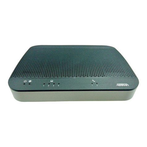
The ADTRAN 411 1 Pots + 1GigE (Micro ONT) is an Optical
Network Terminal (ONT). Figure 1 illustrates the key features on
the Micro ONT.
Figure 1. Micro ONT Key Features
The table opposite provides descriptions for each feature number
above.
Part Number Description
1287787F1 ADTRAN 411 Micro ONT (NA)
1287787F4 ADTRAN 411 Micro ONT (AUS)
4
6
5
1
2 3
7
PWR
VOICE
LAN
FIBER
POWER
VOICE LAN
PWR VOICE LAN
FIBER
FIBER
8
Fiber (FIBER)
Fiber is supplied to the Micro ONT using an SC/APC Fiber
connection located on the rear of the unit.
Ethernet Interface (LAN)
The Micro ONT supports data service through one 10/100/
1000BASE-T Ethernet interface via an RJ-45-style connector.
POTS (VOICE)
Plain Old Telephone Service (POTS) uses in-band signaling tones
and currents to determine call status (for example, call request).
Because POTS allows for the transfer of audio signals below 3.3
kHz, POTS systems are also used for modems that allow data
transmission (referred to as dial up connections).
AC Power
The power feed is +12 VDC from the included AC to DC Adapter.
The adapter plugs into the PWR connector.
UPS
The Micro ONT provides an optional connection for an uninterpre-
table power source (UPS). An UPS is a battery backup system
designed to continue providing power when the primary power
source is lost. Power is supplied to the Micro ONT by a local
power source with battery backup that utilizes the AC power at the
customer premises to charge the battery.
ONT Reset (RESET)
Refer to Figure 1 for the location of the Reset button.
Reset the Micro ONT if you need to reboot the unit. The RESET
button is accessed through an opening on the bottom of the unit.
To reset the Micro ONT, insert a small pin (paper clip) into the
RESET opening and hold the button down for 10 seconds.
The Micro ONT will automatically download the latest provisioning
after the reset process has completed.
Number Feature
1 Single GPON fiber interface with 1.244 Gbps upstream
and 2.488 Gbps downstream
2 POTS (Voice) Interface
3 10/100/1000-BaseT Ethernet Interface (LAN)
4 AC Power Adapter
5 UPS Power/Alarm connector
6 Status LEDs
7 Reset Button
8 Keyholes
ADTRAN 411
Micro ONT
1 POTS + 1 GigE
August 2020
61287787F1-13A
261287787F1-13A
4. Slide the Micro ONT over the Pan Head screws and exert a
small amount of downward pressure to ensure that the top of
the slots are resting on the shafts of the Pan Head screws.
Desktop Installation
The Micro ONT can be located on a desktop. Ensure the Micro
ONT is not located in direct sunlight, next to any thermal obstruc-
tions, or sources of moisture., water or other liquids.
Step 2: Connect Ethernet
The Micro ONT supports a Gbps (10/100/1000BASE-T)
connection to an RJ-45-type connector (LAN).
Refer to Figure 1 and Insert the CAT 6 rated cable in the RJ-45
LAN Port.
Step 3: Connect POTS
Insert the RJ-11 connector in the RJ-11 jack labeled VOICE.
Step 4: Connect Fiber
fWARNING!
CLASS 1 LASER PRODUCT
LASER RADIATION
1310 nm
Do not view directly with optical instruments.
This product contains a Class 1 Laser module that complies with
21 CFR 1040.10 and 1040.11 and IEC 60825-1.
Use of controls or adjustments or performance of procedures
other than those specified herein may result in hazardous
radiation exposure.
Figure 2. GPON Connection
Fiber is installed in an SC/APC connector (FIBER) located on the
rear of the Micro ONT (see Figure 2).
Complete the following steps to install fiber.
1. Refer to Figure 3 and pull the Protective Cover from the SC/
APC Connector.
Figure 3. SC/APC Protective Cover
2. Clean the ends of the Incoming Fiber Connector.
CLASS 1 LASER
PRODUCT
Protective
Cover
SC/APC
Connector
INSTALLATION
Before installing the Micro ONT, inspect it for damage. If damage
has occurred during shipping, file a claim with the carrier and then
contact ADTRAN. For more information, refer to the warranty.
Installation Guidelines
The following are guidelines for this installation.
■Read all warnings and cautions before installing or servicing
the Micro ONT.
■Do not locate the Micro ONT in direct sunlight or next to any
thermal obstructions.
■When the SC/APC fiber connection is not in use, replacing the
Protective Cover will help keep the optical connection clean.
■This product should not come in contact with water or other
liquids.
Installation Overview
To install the Micro ONT, you will need to complete the following
steps:
■Step 1: Position the Micro ONT
■Step 2: Connect Ethernet
■Step 3: Connect POTS
■Step 4: Connect Fiber
■Step 5: Connect 12 VDC Power or UPS Power
Required Tools
Standard technician tools and those listed below are required for
installing the Micro ONT.
■PON power meter with wavelength filtering
■Fiberscope or videoscope
For fiber optic connections, the following are required:
■ODC Fiber cleaning tool
Installation Steps
To install the Micro ONT, complete the following steps.
Step 1: Position the Micro ONT
The Micro ONT can be mounted on a wall, or on a desktop.
Wall Mount Installation
To wall mount the Micro ONT complete the following steps:
gNOTE
Refer to Figure 1 when installing the Micro ONT on a wall.
1. Determine a location for the Micro ONT
2. Use the key holes (2 inches apart) on the back of the Micro
ONT as a template and install two #6 drywall anchors.
3. Install two #6 Pan Head screws. Leave approximately 1/4
inch protruding from the mounting surface.
61287787F1-13A 3
3. Before installing the fiber, use an optical power meter to
measure the power level. The power level should not
exceed –8.0 dBm. Use an appropriate bi-directional optical
attenuator if the power levels are at or above –8.0 dBm. A
level between –8.0 dBm and –28.0 dBm is acceptable, but
levels between –12.0 dBm and –18.0 dBm are optimal.
4. Refer to the and connect the Incoming Fiber Connector.
Figure 4. Fiber Installed
gNOTE
When the SC/APC fiber connection is not in use, replace the
Protective Cover. This will help keep the optical connection clean.
Step 5: Connect 12 VDC Power or UPS Power
Refer to Figure 1 and the following steps when connecting power.
The Micro ONT can be powered by either the 12 VDC connection,
or by using the UPS connection.
wNOTICE
DO NOT connect both power sources as, this will damage the
Micro ONT.
12 VDC Connection
To power the Micro ONT using the 12 VDC connection, complete
the following steps:
1. Plug the supplied 12 V AC/DC Power Converter into the
PWR connection.
2. Connect the power plug to a standard AC outlet. This
immediately turns the unit ON.
UPS Connection
To power the Micro ONT using an UPS, refer to Figure 5 and
complete the following steps:
1. If using the ADTRAN Cable Assembly (see Note below),
connect one end to the Molex Connector and the other to
the UPS. This immediately turns the unit ON.
Figure 5. Molex Connector
gNOTE
ADTRAN offers a 24W UPS (P/N 1187731G3) and GPON Indoor
UPS Power Cable (P/N 1287402G1) for providing an UPS power
source.
Incoming
Fiber
UPS Power/Alarm Table
The following table indicates which pin is associated with each
alarm provided through a UPS connection.
LED STATUS
The LEDs are located beneath the plastic housing and are only
visible after power has been applied. The following table provides
the LED status during normal operations.
TROUBLESHOOTING
The following table provides troubleshooting tips.
Pin-Out Description Alarm
1 Power Input (+12 VDC) -
2 UPS Status - On Battery 1
3 UPS Status - Battery Missing 2
4 Signal Return -
5 Power 12 V Return -
6 UPS Status - Replace Battery 3
7 UPS Status - Low Battery 4
8 No Connection -
Label Status Indication
POWER 

Off
Green
ONT power is Off
ONT power On
FIBER 

2
Off
Green
Green Flashing
Fast
ONT is not active (not Ranged)
ONT is active (Ranged)
ONT is activating (Ranging in
progress)
LAN 

2
Off
Green
Green Flashing
Fast
LAN Port is not connected
LAN Port is connected, but
data is not being transmitted
LAN Port is connected, and
data is being transmitted
VOICE 

2
Off
Green
Green Flashing
Slow
Unequipped or on-hook and
not ringing
Off-hook
On-hook with line in ringing
state
Problem Possible Solution
The LAN LED is
flashing red
■Use an optical power meter to check
the receiving power to see if it between
–28 dbm and –8 dbm.
■Reset the ONT using the Reset button.
If the ONT fails again, replace the ONT
with another unit.
The FIBER LED is off
when the Ethernet cable
is connected
Check the FIBER connection, or check to
see if the Ethernet service is disabled. Con-
tact the Central Office for verification.
CAUTION!
SUBJECT TO ELECTROSTATIC DAMAGE
OR DECREASE IN RELIABILITY
HANDLING PRECAUTIONS REQUIRED
Warranty: ADTRAN will replace or repair this product within the warranty period if it does not
meet its published specifications or fails while in service. Warranty information can be
found online at www.adtran.com/warranty.
Trademarks: Brand names and product names included in this document are trademarks,
registered trademarks, or trade names of their respective holders.
Copyright © 2020 ADTRAN, Inc. All Rights Reserved.
ADTRAN CUSTOMER CARE:
From within the U.S. 1.888.423.8726
From outside the U.S. +1 256.963.8716
PRICING AND AVAILABILITY 1.800.827.0807
*61287787F1-13A*
SPECIFICATIONS
Specifications for the Micro ONT are as follows:
■Electrical
♦Voltage: 12.0 V typical
♦Minimum Voltage: 10.0 V
♦Maximum Voltage: 13.9 V
♦Maximum Power Consumption: 10 W
The Power LED is Off ■Make sure the power cable connector
is properly seated in the ONT power
input.
■Verify that the power adapter is
plugged into a live AC outlet.
■Check the power cable for shorts or
breaks.
■Disconnect the power input connector
at the ONT; use a voltmeter to verify
that the proper voltage level is present
on the 12 V pin (power and power
return) from the power adapter.
■Check the UPS cable and ensure it is
properly seated in the UPS port.
■Disconnect the UPS cable and use a
voltmeter to check for 12 VDC
between pins 1 and 5.
■Check the UPS cable for shorts or
opens.
The LAN LED is green ■During boot-up, the LED will flash
green. This is normal. Once boot-up is
complete, the LED will become solid
green. When data is transmitted, the
LED will flash green. If the LED
remains solid green, contact the
Central Office to verify that the ONT
serial number, password, and vendor
ID match those provisioned in the
database.
■If provisioning is correct, have the
Central Office determine if there are
alarms on the PON feeding the ONT. If
no alarms exist, use an optical power
meter to troubleshoot the fiber
network.
Problem Possible Solution ■Physical
♦Width: 2.8 in (7.1 cm)
♦Depth: 4.0 in (10.2 cm)
♦Height: 1.2 in (3.0 cm)
♦Weight: 1 lbs (0.45 kg)
■Environmental
♦Operational Temperature: 32°F to +104°F (0°C to +40°C)
♦Storage Temperature: –4°F to 122°F (–20°C to +50°C)
♦Relative Humidity: 90%, noncondensing
■Optical
♦TX min power: +0.5 dBm
♦TX max power: +5.0 dBm
♦RSSI max sensitivity: –27 dBm
♦RX overload: –8 dBm
♦TX wavelength: 1310 nm typical
♦RX wavelength: 1490 nm typical
MAINTENANCE
The Micro ONT does not require routine hardware maintenance
for normal operation. We do not recommend that you attempts
repairs in the field. Obtain repair services by returning the
defective unit to ADTRAN. Refer to the warranty for further infor-
mation. Field support for software is provided through upgrade
facilities.
SAFETY AND REGULATORY
Refer to the Safety and Regulatory Notice for this product
(P/N 61287787F1-17) for detailed safety and regulatory infor-
mation.
Consultez l'avis sur la sécurité et la conformité à la réglementation
pour ce produit (P/N 61287787F1-17) pour obtenir des renseigne-
ments détaillés sur la sécurité et la réglementation.
Ausführliche Sicherheits- und regulatorische Informationen sind in
der Konformitätserklärung zur Sicherheit und Einhaltung von
Normen zu diesem Produkt (61287787F1-17) aufgeführt.
Documentation for ADTRAN Network Solutions products is available for
viewing and download directly from the ADTRAN Support Community
website.
Go to: https://supportforums.adtran.com/welcome
Registration is required.
ADTRAN offers training courses on our products, including customized
training and courses taught at our facilities or at customer sites.
For inquiries, go to: http://adtran.com/training
The following online documents and resources provide additional information for this product:
Total Access 5000 GPON OLT User Interface Guide
Total Access 5000 Series Fiber to the Premises Deployment Guide
This manual suits for next models

2

Other ADTRAN Network Hardware manuals

ADTRAN T400 Instruction Manual

ADTRAN

ADTRAN T400 Instruction Manual

ADTRAN ATLAS 550 User manual

ADTRAN

ADTRAN ATLAS 550 User manual

ADTRAN T200 HTU-R Instruction Manual

ADTRAN

ADTRAN T200 HTU-R Instruction Manual

ADTRAN GPON 452 User manual

ADTRAN

ADTRAN GPON 452 User manual

ADTRAN Total Access 1248 User manual

ADTRAN

ADTRAN Total Access 1248 User manual

ADTRAN SHDSL T1 Instruction Manual

ADTRAN

ADTRAN SHDSL T1 Instruction Manual

ADTRAN NetVanta 1700801G1 User manual

ADTRAN

ADTRAN NetVanta 1700801G1 User manual

ADTRAN Total Reach DDS-DP 5 Series Instruction Manual

ADTRAN

ADTRAN Total Reach DDS-DP 5 Series Instruction Manual

ADTRAN EXPRESS 6503 User manual

ADTRAN

ADTRAN EXPRESS 6503 User manual

ADTRAN MX2800 STS-1 User guide

ADTRAN

ADTRAN MX2800 STS-1 User guide

ADTRAN TRACER 5045 User guide

ADTRAN

ADTRAN TRACER 5045 User guide

ADTRAN T200 H4R User manual

ADTRAN

ADTRAN T200 H4R User manual

ADTRAN 1200130L1 User manual

ADTRAN

ADTRAN 1200130L1 User manual

ADTRAN 1442390G1 User manual

ADTRAN

ADTRAN 1442390G1 User manual

ADTRAN 1442880G1 User manual

ADTRAN

ADTRAN 1442880G1 User manual

ADTRAN Total Access 300 Instruction Manual

ADTRAN

ADTRAN Total Access 300 Instruction Manual

ADTRAN DSU IV ESP User manual

ADTRAN

ADTRAN DSU IV ESP User manual

ADTRAN SFP+ User manual

ADTRAN

ADTRAN SFP+ User manual

ADTRAN ISU 128 User manual

ADTRAN

ADTRAN ISU 128 User manual

ADTRAN Total Access 900E Series User manual

ADTRAN

ADTRAN Total Access 900E Series User manual

ADTRAN Express 6530 6530 Manual

ADTRAN

ADTRAN Express 6530 6530 Manual

ADTRAN GPON 452 User manual

ADTRAN

ADTRAN GPON 452 User manual

ADTRAN Total Access DSLAM 16-Port ADSL2+ Access Module... User manual

ADTRAN

ADTRAN Total Access DSLAM 16-Port ADSL2+ Access Module... User manual

ADTRAN T200 IDSL OCU-R Instruction Manual

ADTRAN

ADTRAN T200 IDSL OCU-R Instruction Manual

Popular Network Hardware manuals by other brands

Burg Wächter SNVR-11612 Quick installation guide

Burg Wächter

Burg Wächter SNVR-11612 Quick installation guide

Multitech Multi-Tech RouteFinder SOHO RF820 user guide

Multitech

Multitech Multi-Tech RouteFinder SOHO RF820 user guide

Vision 2GIG-Z-BRG1-433 Operation manual

Vision

Vision 2GIG-Z-BRG1-433 Operation manual

NEC N8151-51A Guide usage notes

NEC

NEC N8151-51A Guide usage notes

STONEFLY DR365-1204 Setup guide

STONEFLY

STONEFLY DR365-1204 Setup guide

SMC Networks SMC91C95 product manual

SMC Networks

SMC Networks SMC91C95 product manual

NEC N8151-46 user guide

NEC

NEC N8151-46 user guide

Ubiquiti UBI-POWERBEAM-M5-300 quick start guide

Ubiquiti

Ubiquiti UBI-POWERBEAM-M5-300 quick start guide

Cisco CGR 1240 Replacing Manual

Cisco

Cisco CGR 1240 Replacing Manual

Renesas RX600 Series user manual

Renesas

Renesas RX600 Series user manual

TC Electronic DB6 user manual

TC Electronic

TC Electronic DB6 user manual

EVOC EIC-3011 user manual

EVOC

EVOC EIC-3011 user manual

Enterasys 6E2xx Local Management User’s Guide

Enterasys

Enterasys 6E2xx Local Management User’s Guide

FrontLine ComProbe USB 2.0 quick start guide

FrontLine

FrontLine ComProbe USB 2.0 quick start guide

Matrix Switch Corporation MSC-HD81DEL product manual

Matrix Switch Corporation

Matrix Switch Corporation MSC-HD81DEL product manual

Bay Networks BayStack 400-ST1 installation manual

Bay Networks

Bay Networks BayStack 400-ST1 installation manual

Cisco 7246 - uBR Router user guide

Cisco

Cisco 7246 - uBR Router user guide

Gigamon GigaVUE H Series Hardware installation guide

Gigamon

Gigamon GigaVUE H Series Hardware installation guide

manuals.online logo
manuals.online logoBrands
  • About & Mission
  • Contact us
  • Privacy Policy
  • Terms and Conditions

Copyright 2025 Manuals.Online. All Rights Reserved.