manuals.online logo
Brands
  1. Home
  2. •
  3. Brands
  4. •
  5. ADTRAN
  6. •
  7. Network Hardware
  8. •
  9. ADTRAN jobAid User manual

ADTRAN jobAid User manual

jobAid
1
DESCRIPTION
The 10G DWDM Tunable XFP is a fully duplex serial electric,
serial optic device with both transmit and receive functions
contained in a single module that provides a high speed serial
link at 10 Gbs. The Tunable XFP is controlled by software on the
host module and can operate on the full C-band supporting
Channels 17 through 60. Installed in the appropriate host module,
the Tunable XFP provides a 10 Gigabit interface to the supporting
system. Refer the documentation provided with the host module
for information on configuring the XFP.
The transmit side of the Tunable XFP converts serial NRZ
electrical data at the 10 Gbs line rate to a standard compliant
optical signal. The receive side converts the incoming DC
balanced serial NRZ optical data at the 10 Gbs line rate into serial
electrical data.
NOTE
To ensure compatibility, refer to the documentation provided
with the host module.
The following features are supported on the Tunable XFP:
•1529.55 ~ 1563.86 nm optical signals for up to 80 km reach
•Low power consumption (<3.5 W max)
•Bit error rate 10^–12
CAUTION
!
Due to compliance certification requirements, use only XFPs
supplied by ADTRAN with the host module. ADTRAN cannot
certify system integrity with other XFPs.
Small Form-Factor Pluggable
10G DWDM Tunable XFP
OPERATIONAL SPECIFICATIONS
•Transmit Wavelength: Tunable 1529.55 ~ 1563.86 nm
(Channels 17 through 60)
•Receive Wavelength: 1528.77 to 1600 nm
•Data Rate: 9.95 Gbs to 11.35 Gbs (see table below)
•Optical transmit levels: –1.0 to +3.0 dBm
•Optical receive level: –24.0 to –7.0 dBm
•Dispersion Tolerance: -400ps/nm to 1600ps/nm
•Dispersion penalty maximum: 2.5dB (-400 to 1600ps/nm)
•Minimum Span Attenuation: 10 dB
•Optical distance: 80 km maximum
•Optical connectors: LC
•Extended Environmental Support:
oOperational temperature range: –5°C to +60°C
oStorage temperature range: –40°C to +85°C
oRelative humidity to 85%, noncondensing
INSTALLATION
Before installing the equipment, inspect the Tunable XFP. If
damage has occurred during shipping, file a claim with the
carrier, and then contact ADTRAN Customer Support. For more
information, refer to the warranty.
To install the Tunable XFP into an appropriate module, complete
the following steps:
NOTE
Do not remove the protective end cap from the XFP until the fiber
optic cable is ready to be connected.
1. Insert the Tunable XFP into the XFP cage on the module.
Ensuring that the latch handle on the XFP is facing upward,
slide the XFP all the way into the XFP cage until there is an
audible “click”.
NOTE
The latch on the XFP is for removal only. When removing the
XFP, rotate the latch away from the XFP, the XFP should easily
slide out of the cage.
2. Do not remove the protective end cap until the optical fiber
connection is made.
Without FEC1
1. Forward Error Correction (FEC) at BER 1E-12, input power -7 to -19 dBm
With FEC2
2. Forward Error Correction (FEC) at BER 1E-4, input power -7 to -24 dBm
Data Rate BOL EOL BOL EOL
9.95Gbps >26 dB >27 dB NA NA
Up to 10.7Gbps NA NA >17.5 dB >18.5 dB
Up to 11.1Gbps NA NA >18.5 dB >19.5 dB
Up to 11.35Gbps NA NA >18.5 dB >19.5 dB
CLEI: BVL3AP6D_ _
Product P/N: 1442985G1C
Issue Date: March 2012
Document P/N: 61442985G1C-22A
261442985G1C-22A
NOTICE
It is recommended that the protective end cap remain on
whenever the transceiver optical fiber connector is not inserted.
Continue the installation and turn-up of the host module using
the instructions in the Job Aid provided with the module or other
system-level documentation available online at www.adtran.com.
SAFETY AND REGULATORY COMPLIANCE
WARNING
!
Read all warnings and cautions before installing or servicing this
equipment.
CAUTION
C
This product uses a Class 1 Laser module that complies with 21
CFR 1040.10 and 1040.11 and IEC 60825-1, IEC 60825-2, EN 60825-
1 and EN 60825-2. For continued compliance with the above
standards, only approved Class 1 laser modules from an
ADTRAN approved vendor list (located on the ADTRAN
website) should be installed in this product. ADTRAN cannot
certify system integrity with other laser modules.
CAUTION
!
•Electrostatic Discharge (ESD) can damage electronic modules.
When handling modules, wear an antistatic discharge wrist
strap to prevent damage to electronic components. Place
modules in antistatic packing material when transporting or
storing. When working on modules, always place them on an
approved antistatic mat that is electrically grounded.
•Per GR-1089-CORE the system is designed and intended for
installation as part of a Common Bonding Network (CBN).
The system is not designed nor intended for installation as
part of an Isolated Bonding Network (IBN).
•Per GR-1089-CORE Section 9, this product does not have an
internal DC connection between battery return and frame
ground. This product can be installed in a DC-I (isolated) or
DC-C (common) installation. For installations where other
cards or the host system have internal connections between
battery return and frame ground, the system would be
intended for deployment only in a DC-C installation.
•The chassis frame ground terminal must be connected to an
earth ground to ensure that the metal enclosure of the XFP is
properly grounded via the backplane connector.
NOTE
•The Gigabit Ethernet port(s) are optical and therefore are not
classified as any type of port as defined in Appendix B of GR-
1089-CORE.
•The Tunable XFP is compliant with SFF-8472 “Digital
Diagnostics Monitoring Interface for Optical Transceivers,”
Revision 9.3.
•The Tunable XFP is compliant with the XFP Multi-Source
Agreement (MSA).
•The Tunable XFP is designed to be deployed in GR-3108-
CORE environmental class 1 as defined in GR-3108-CORE.
This product is NRTL Listed to the applicable UL Standards. The
product is designed to meet the applicable requirements of
Telcordia GR-63-CORE, and GR-1089-CORE.
This product has also been evaluated to international safety
standards EN 60950-1, AS/NZS 60950.1, and IEC 60950-1. This
product meets the requirements for CE marking under the EMC
Directive and Low Voltage Directive. Standards used to demon-
strate Compliance are EN 300 386 and EN 60950. The Tunable
XFP is intended for deployment in Central Office (Telecommuni-
cation Center) type facilities, EEEs, EECs Access or Trunk
Network Locations), and locations where the NEC applies (for
example, Customer Premises).
The Tunable XFP is to be installed in ADTRAN products in
Restricted Access Locations only, and installed by trained service
personnel.
This device complies with Part 15 of the FCC rules. Operation is
subject to the following two conditions:
1. This device may not cause harmful interference
2. This device must accept any interference received, including
interference that may cause undesired operation.
The product also complies with ETSI EN 300 386 “Electromag-
netic compatibility and Radio spectrum Matters (ERM); Telecom-
munication network equipment; Electromagnetic Compatibility
(EMC) requirements.”
Changes or modifications not expressly approved by ADTRAN
could void the user's authority to operate this equipment.
The Tunable XFP is designed to meet the following environ-
mental classes:
•ETSI EN 300 019-1-1 “Classification of environmental
conditions; Storage,” Class 1.2
•ETSI EN 300 019-1-2 “Classification of environmental
conditions; Transportation,” Class 2.3
•ETSI EN 300 019-1-3 “Classification of environmental
conditions; Stationary use at weather-protected locations,”
Class 3.2
The equipment is designed to function without degradation
during exposure to all test severities per Class 3.2.
The 10G DWDM Tunable XFP meets EU RoHS Directive 2002/
95/EC and/or applicable exemptions. Refer to www.adtran.com
for further information on RoHS/WEEE.
61442985G1C-22A 3
FRANÇAIS
AVERTISSEMENT
!
Lisez tous les avertissements et mises en garde avant l’installation
de cet équipement ou la réalisation de toute opération de
maintenance.
ATTENTION
C
Ce produit utilise un module laser de classe 1 qui conforme aux
normes 21 CFR 1040.10, 1040.11 et IEC 60825-1 et -2. Pour assurer
la conformité aux normes mentionnées plus haut, seuls des
modules laser de classe 1 approuvés provenant d’une liste de
fournisseurs certifiés par ADTRAN (disponible sur le site
d’ADTRAN) doivent être installés sur ce produit. ADTRAN ne
peut certifier l’intégrité d’un système doté d’autres modules laser.
ATTENTION
!
•L'ESD (décharge électrostatique) peut endommager les
modules électroniques. Lors de la manipulation des modules,
portez un bracelet de décharge antistatique pour éviter
d’endommager les composants électroniques. Placez les
modules dans un emballage antistatique lors du transport ou
du stockage. Lorsque vous travaillez sur les modules, placez-
les toujours sur un tapis antistatique certifié muni d’un
branchement de mise à la terre.
•Selon le document GR-1089-CORE, ce système est conçu et
prévu pour une installation intégrée à un réseau de masse
maillé. Ce système n’est pas conçu ni prévu pour une
installation intégrée à un réseau de masse isolé (IBN).
•Selon le document GR-1089-CORE section 9, ce produit n’est
pas équipé d’une connexion DC interne entre le retour de la
batterie et la masse du châssis. Ce produit peut être installé
dans une configuration DC-I (isolé) ou DC-C (commun). Pour
les installations où les autres cartes ou le système hôte
possèdent des connexions internes entre le retour de
l’accumulateur et la mise à la terre de l’armature, le système
est prévu pour le déploiement de configuration DC-M unique.
•La borne de mise à la terre du châssis doit être branchée à une
prise de terre afin d’assurer que le boîtier métallique de la XFP
est correctement mis à la terre grâce au connecteur de face
arrière.
Ce produit est conçu pour répondre aux classes environnemen-
tales suivantes :
•ETSI EN 300 019-1-1 "Classification des conditions
d'environnement; Entreposage," classe 1.2
•ETSI EN 300 019-1-2 "Classification des conditions
d'environnements; Transport," classe 2.3
•ETSI EN 300 019-1-3 "Classification des conditions
d'environnements; l'utilisation à poste fixe dans des endroits
protégés contre les intempéries," classe 3.3
L'équipement est conçu pour fonctionner sans dégradation lors
des tests à tous les niveaux de sévérité, suivant les spécifications
de la classe 3.3 de l'ETSI EN 300 019-1-3.
Ce produit est conforme à la directive européenne RoHS 2002/
95/CE et/ou aux exonérations applicables. Reportez-vous à
www.adtran.com pour de plus amples renseignements sur
RoHS/WEEE.
DEUTSCH
WARNUNG
!
Lesen Sie sich alle Warn- und Sicherheitshinweise durch, bevor
Sie dieses Gerät installieren oder warten.
CAUTION
C
Dieses Produkt nutzt ein mit den Richtlinien 21 CFR 1040.10 und
1040.11 und IEC 60825-1 und -2 konformes Class 1 Lasermodul.
Damit die obigen Richtlinien auch in Zukunft eingehalten werden
können, dürfen ausschließlich Class 1 Lasermodule von einem
von ADTRAN zugelassenen Anbieter in dem Produkt installiert
werden (erhältlich auf der Website von ADTRAN). ADTRAN
garantiert nicht für die Systemintegrität bei anderen
Lasermodulen.
VORSICHT
!
•Elektrostatische Entladungen können elektronische Module
beschädigen. Tragen Sie beim Umgang mit Modulen ein
Erdungsarmband, um Schäden an den elektronischen
Komponenten zu vermeiden. Transportieren oder lagern Sie
Module in antistatischem Verpackungsmaterial. Bei der Arbeit
an den Modulen, achten Sie darauf, diese stets auf
antistatische, elektrisch geerdete Matten zu legen.
•Laut GR-1089-CORE dient dieses System zur Installation in
einer gemeinsamen Potentialausgleichsanlage. Dieses System
dient nicht zur Installation in einer isolierten
Potentialausgleichsanlage.
•Laut GR-1089-CORE Abschnitt 9 verfügt dieses Produkt nicht
über eine interne DC-Verbindung zwischen den Batterien und
der Gehäusemasse. Dieses Produkt kann entweder in einer
DC-I (isolierten) oder DC-C (gemeinsamen) Anlage installiert
werden. Installationen, in denen für andere Karten oder das
Host-System interne Verbindungen zwischen den Batterien
und der Gehäusemasse bestehen, dienen ausschließlich für
den Einsatz in DC-C-Anlagen.
•Die Erdungsschiene des Rahmens muss an eine Bodenstation
angeschlossen werden, um sicherzustellen, dass das
Metallgehäuse des XFP vorschriftsmäßig über den
Rückwandanschluss geerdet ist.
Dieses Produkt wurde entsprechend der folgenden Umwelt-
klassen entwickelt:
•ETSI EN 300 019-1-1 "Klassifikation von Umweltbedingungen,
Lagerung," Klasse 1.2
•ETSI EN 300 019-1-2 "Klassifikation von Umweltbedingungen,
Transport," Klasse 2.3
•ETSI EN 300 019-1-3 "Klassifikation von Umweltbedingungen,
Stationärer Einsatz ohne Witterungseinflüsse," Klasse 3.3
Dieses Gerät funktioniert ohne Leistungsabfall während aller für
Klasse 3.3 von ETSI EN 300 019-1-3 vorgeschriebenen Belastung-
stests.
Dieses Produkt erfüllt die EU RoHS Richtlinie 2002/95/EC und/
oder gültige Ausnahmen. Bitte besuchen Sie www.adtran.com für
ausführlichere Informationen zu RoHS/WEEE.
C A U T I O N
C A U T I O N
!
SUBJECT TO ELECTROSTATIC DAMAGE
OR DECREASE IN RELIABILITY.
HANDLING PRECAUTIONS
REQUIRED.
Warranty: ADTRAN will replace or repair this product
within the warranty period if it does not meet its
published specifications or fails while in
service. Warranty information can be found
online at www.adtran.com/warranty.
©2012 ADTRAN, Inc. All Rights Reserved.
ADTRAN CUSTOMER CARE:
From within the U.S. 1.800.726.8663
From outside the U.S. +1 256.963.8716
PRICING AND AVAILABILITY 1.800.827.0807
*61442985G1C-22A*

This manual suits for next models

1

Other ADTRAN Network Hardware manuals

ADTRAN 1200312L5 User manual

ADTRAN

ADTRAN 1200312L5 User manual

ADTRAN NetVanta 2300 User manual

ADTRAN

ADTRAN NetVanta 2300 User manual

ADTRAN QFO-C Instruction Manual

ADTRAN

ADTRAN QFO-C Instruction Manual

ADTRAN Total Access Octal ADSL User manual

ADTRAN

ADTRAN Total Access Octal ADSL User manual

ADTRAN 1442880G1 User manual

ADTRAN

ADTRAN 1442880G1 User manual

ADTRAN Cable T1 ESF CSU ACE User manual

ADTRAN

ADTRAN Cable T1 ESF CSU ACE User manual

ADTRAN 1200184L1 User manual

ADTRAN

ADTRAN 1200184L1 User manual

ADTRAN FXS/DPO/PLAR 1109403L2 Instruction Manual

ADTRAN

ADTRAN FXS/DPO/PLAR 1109403L2 Instruction Manual

ADTRAN 1490 TX User manual

ADTRAN

ADTRAN 1490 TX User manual

ADTRAN FXS+ Dual User manual

ADTRAN

ADTRAN FXS+ Dual User manual

ADTRAN TSU LT User manual

ADTRAN

ADTRAN TSU LT User manual

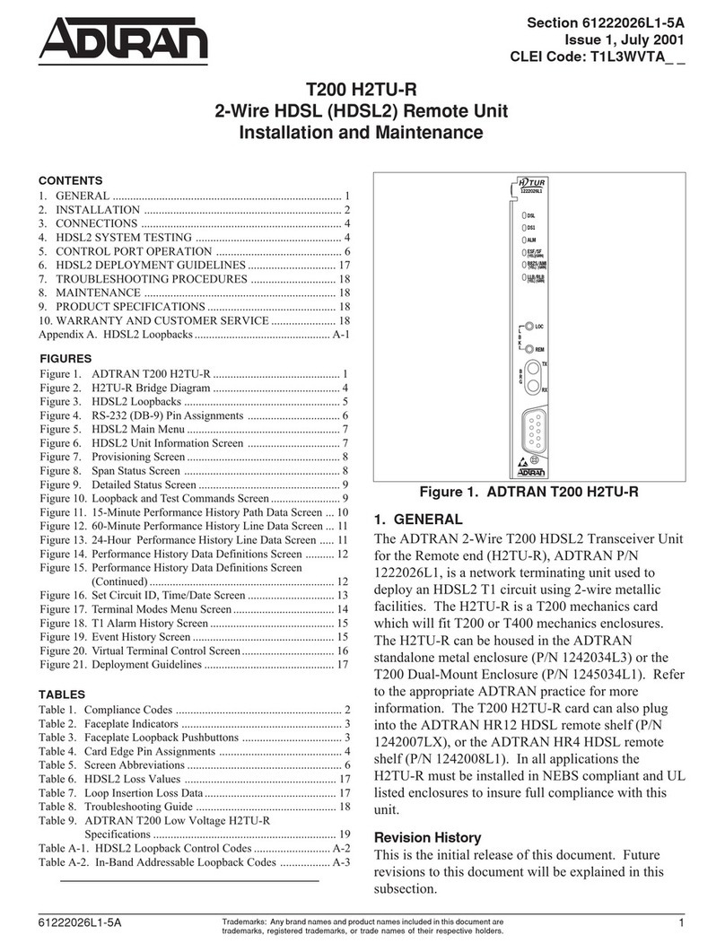
ADTRAN T200 IDSL Instruction Manual

ADTRAN

ADTRAN T200 IDSL Instruction Manual

ADTRAN Stub Routing User manual

ADTRAN

ADTRAN Stub Routing User manual

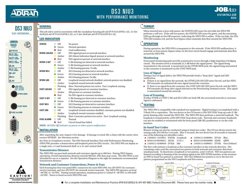
ADTRAN DS3 NIU3 User manual

ADTRAN

ADTRAN DS3 NIU3 User manual

ADTRAN ATLAS 800 Series Module QUAD E1 User manual

ADTRAN

ADTRAN ATLAS 800 Series Module QUAD E1 User manual

ADTRAN Total Access 300 Series Product manual

ADTRAN

ADTRAN Total Access 300 Series Product manual

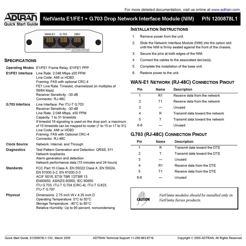
ADTRAN NetVanta E1/FE1 Network Interface Module User manual

ADTRAN

ADTRAN NetVanta E1/FE1 Network Interface Module User manual

ADTRAN DSU III ARdc User manual

ADTRAN

ADTRAN DSU III ARdc User manual

ADTRAN MX410 User manual

ADTRAN

ADTRAN MX410 User manual

ADTRAN T3SU 300 User manual

ADTRAN

ADTRAN T3SU 300 User manual

ADTRAN 1203060L1 User manual

ADTRAN

ADTRAN 1203060L1 User manual

ADTRAN HDSL4 User manual

ADTRAN

ADTRAN HDSL4 User manual

ADTRAN FNID Manual

ADTRAN

ADTRAN FNID Manual

ADTRAN TSU LT User manual

ADTRAN

ADTRAN TSU LT User manual

Popular Network Hardware manuals by other brands

Telebyte 458-LM-E2-36 quick start guide

Telebyte

Telebyte 458-LM-E2-36 quick start guide

ZyXEL Communications NSA325 quick start guide

ZyXEL Communications

ZyXEL Communications NSA325 quick start guide

Alvarion BreezeACCESS II System manual

Alvarion

Alvarion BreezeACCESS II System manual

AAON FWS-2350 manual

AAON

AAON FWS-2350 manual

ICP DAS USA Network Device I-7011 user manual

ICP DAS USA

ICP DAS USA Network Device I-7011 user manual

Altronix NetWay G Series installation guide

Altronix

Altronix NetWay G Series installation guide

Compaq WL110 user guide

Compaq

Compaq WL110 user guide

Airlink101 AWMB100 Quick installation guide

Airlink101

Airlink101 AWMB100 Quick installation guide

Symbol 1-PortPower-over-Ethernet installation guide

Symbol

Symbol 1-PortPower-over-Ethernet installation guide

MikroTik RouterBOARD 750 Quick setup guide and warranty information

MikroTik

MikroTik RouterBOARD 750 Quick setup guide and warranty information

Addonics Technologies RT134DAMS user guide

Addonics Technologies

Addonics Technologies RT134DAMS user guide

UeeVii CPE452 user manual

UeeVii

UeeVii CPE452 user manual

3M BPEO Size 1 installation instructions

3M

3M BPEO Size 1 installation instructions

Patton electronics 2888 Getting started guide

Patton electronics

Patton electronics 2888 Getting started guide

TXper nVR-15W Quick installation guide

TXper

TXper nVR-15W Quick installation guide

Anywave PA-25W user manual

Anywave

Anywave PA-25W user manual

Quectel FWT 3G/4G quick start guide

Quectel

Quectel FWT 3G/4G quick start guide

Allied Telesis POTS24 datasheet

Allied Telesis

Allied Telesis POTS24 datasheet

manuals.online logo
manuals.online logoBrands
  • About & Mission
  • Contact us
  • Privacy Policy
  • Terms and Conditions

Copyright 2025 Manuals.Online. All Rights Reserved.