Advance Lifts 2000 Series User manual
Dock Lift Owner’s Manual
This manual is an important
document. Keep it with the
machine or located where
readily available to operators
and maintenance personnel
for reference purposes.
This manual is an important
document. Keep it with the
machine or located where
readily available to operators
and maintenance personnel
for reference purposes.

INSTALLATION, OPERATION AND MAINTENANCE MANUAL
FOR THE FOLLOWING DOCK LIFT MODEL NUMBERS
Throughout this manual, units are refered to by series. Each series has special
installation, maintenance and safety requirements.
2000 Series Lifts (2010, 2020, 2030, 2040, 2050, 2060, 2070, 2080, 2090, 2400)
2000K Series Lifts (2010K, 2500K)
3000 Series Lifts (3200, 3210, 3220, 3230, 3240, 3250, 3260, 3270,3280,3300, 3310,
3320, 3330, 3340, 3350, 3360, 3370, 3380, 3400, 3410, 3420, 3430,
3440, 3450, 3460, 3470, 3480, 3500, 3510, 3520, 3530, 3540, 3550,
3560, 3570, 3580, 3600, 3610, 3620, 3630, 3640, 3650, 3660, 3670,
3680)
4000 Series Lifts (4100, 4120, 4130, 4140, 4150, 4160, 4170, 4180, 4200, 4210,4220,4230,
4240, 4250, 4260, 4270, 4280, 4300, 4310, 4320, 4330, 4340, 4350,
4360, 4370, 4380, 4400, 4410, 4420, 4430, 4440, 4450, 4460, 4470,
4480)
T-Series Lifts (T2-50608, T2-60608, T2-55609, T2-55610, T2-55708, T2-55709, T2-50710,
T2-50808, T2-50809, T2-50810, T3-50608, T3-60608, T3-60609, T3-60610,
T3-60708, T3-60709, T3-60710, T3-60808, T3-60809, T3-60810)
OTHER______________________________________________________________________

Dock Lift Installation, Operation, and Maintenance Manual
In any correspondence with your distributor or the factory you will need the following
information:
Model Number________________________________ Serial Number______________________________
Installation location: __________________________________
__________________________________
__________________________________
Distributor Information: ____________________________________________
_________________________________
_________________________________
_________________________________
Advance Lifts, Inc.
701 S. Kirk Road
St. Charles, IL 60174-3428
Toll Free 1-800-843-3625
Sales Fax 1-630-584-9405
Parts and Service Fax 1-630-584-6837
E-mail: Parts@advancelifts.com
*Advance Lifts, Inc. furnishes one manual with each unit. Additional manuals are available at
$25.00 each.
P 1-1
At Initial Installation, determine proper motor/pump rotation by starting the motor in
very short intervals to prevent permanent pump damage. Running the pump
backwards will damage it. See the Installation Instructions, Section 4, for proper
procedure.

SECTION 2: INDEX & INTRODUCTION
Identification ………………………………………………………………………… Section 1
Index & Introduction …………………………………………………………….….. Section 2
*Responsibilities of Owners/Users ………………………………………………….Section 3
*Installation Instructions ……………………………………………….……………..Section 4
*Operating Instructions ………………………………………………...……………. Section 5
*Maintenance Instructions ………………………………………………………… Section 6
Power Unit Assemblies ……...………………………………………………………Section 7
Hydraulic Details …............................................................................................Section 8
General hydraulic information
Schematics
Fluid recommendations & seal compatibility
Pressure information for hoses & pipes
Component information
Electrical Details …………………………………………………………………….. Section 9
Schematics
Controller specifications
Component information
Wire size charts
Identification and Label Placement …………………………………………….. Section 10
Troubleshooting Hints ………………………………………………………….... Section 11
Warranty …………………………………………………………………………… Section 12
Optional Information……………………………………………………………… Section 13
*Mandatory reading before attempting installation.
INTRODUCTION
Congratulations, the equipment that you have purchased is of the highest quality. Your
Advance Lift will provide you with many years of trouble free service in return for the minimal
maintenance described in this manual.
Please be sure that no individual is allowed to operate the lift until they have been fully
familiarized with operating instructions in this manual. Also insure that at least one person at the
lift site is familiar with the maintenance section of this manual and is assigned responsibility for
doing the maintenance on a regular basis.
Please note that the lift has a metal nameplate attached to it that contains information such as
the model number, capacities, and the serial number. Do not remove the nameplate. Be sure
that no operator ever exceeds the capacities shown on the nameplate or they may cause
damage to the lift or injure personnel. Also, be sure to have the serial number of the lift handy if
you have to call the factory. That serial number identifies your specific lift and will allow factory
personnel to give you the most thorough and timely assistance possible.
This manual is under constant review and we would appreciate any constructive suggestions
that may enhance its usefulness. Please send your suggestions to Advance Lifts, Inc Attn:
Service Manager
Thank you for purchasing our product.
P 2-1

SECTION 3:RESPONSIBILITIES OF OWNERS & USERS
Basic Principles: Owners/users shall apply sound principles of safety, training, inspection,
maintenance, and expected operating environment.
It shall be the responsibility of the owner/user to advise the manufacturer where deflection may
be critical to the application.
Manuals: Owners/users shall keep and maintain a copy of the operating and maintenance
manual(s) and ensure its availability to operating and maintenance personnel.
Inspection and Maintenance: It shall be the responsibility of the users to inspect and maintain
the industrial scissors lift as required to ensure proper operation. The frequency of inspection
and maintenance shall be based upon the manufacturer’s recommendations and be compatible
with operating conditions and the severity of the operating environment.
Industrial scissors lifts that are not in proper operating condition shall be immediately removed
from service until repaired. Maintenance and repairs shall be made by a qualified person and
the repairs shall be in conformance with the manufacturer’s recommendations.
Maintenance Safety Precautions: Before adjustments and repairs are started on an industrial
scissors lift, the following precautions shall be taken as applicable:
1.Remove the load from the platform.
2.Lower platform to the full down position, if possible or secure by maintenance device
and/or blocking as described by the manufacturer to prevent unintended platform
movement.
3.Relieve system pressure from all circuits before loosening or removing any components.
4.All controls in the “off’ position and all operating features secured from inadvertent motion
by brakes, blocks, or other means.
5.Disconnect power and follow established owner/user lockout/tag out policies.
6.Follow precautions and directions as specified by the manufacturer.
Replacement Parts: When parts or components are replaced, they shall be replaced with parts
or components approved by the original manufacturer of the industrial scissors lift.
Maintenance Training: The owner/user shall ensure only qualified personnel inspect and
maintain the industrial scissors lift in accordance with the sections: Inspection and Maintenance,
Replacement Parts and Operator Training and the manufacturer’s recommendations as
described in the maintenance manual.
Operator Training: An owner/user, who directs or authorizes an individual to operate an
industrial scissors lift, shall ensure that the individual has been:
1.Trained in accordance with the manufacturer’s operating manual.
2.Made aware of the responsibilities of operators as outlined under the Operators Section of
this manual.
3.Retrained, if necessary, based on the owners/user’s observation and evaluation of the
operator.
Modifications: Modifications and additions shall not be performed without the manufacturer’s
prior written approval. Where such authorization is granted, capacity, operation, and
maintenance instruction plates, tags, or decals shall be changed accordingly.
P 3-1

SECTION 3. RESPONSIBILITIES OF OWNERS & USERS (Continued)
Responsibility of Operators
Basic Principles: Operators shall apply sound principles of safety and good judgment in the
application and operation of the scissors lift, with consideration given to its intended use and
expected operating environment. Since the operator is in direct control of the industrial scissors
lift, conformance with good safety practices is the responsibility of the operator. The operator
shall make decisions on the consideration for the fact that his or her own safety as well as the
safety of other personnel on or near the scissors lift is dependent on those decisions.
General Training: Only personnel who have received general instructions regarding the
inspection, application and operation of industrial scissors lifts, including recognition and
avoidance of hazards associated with their operation, shall operate an industrial scissors lift.
Such topics covered shall include, but not necessarily be limited to, the following issues and
requirements:
1. A pre-start inspection
2. Responsibilities associated with problems or malfunctions affecting the operation of the
industrial scissors lift
3. Factors affecting stability
4. The purpose of placards and decals
5. Workplace inspection
6. Safety rules and regulations
7. Authorization to operate
8. Operator warnings and instructions
9. Actual operation of the industrial scissors lift. Under the direction of a qualified person,
the trainee shall operate the industrial scissors lift for a sufficient period of time to
demonstrate proficiency in actual operation of the industrial scissors lift.
Prestart Inspection: Before use each day or at the beginning of each shift, the industrial
scissors lift shall be given a visual inspection and functional test including but not limited to the
following:
1. Operating and emergency controls
2. Safety devices
3. Air or hydraulic system leaks
4. Electrical cables and wiring harness
5. Loose or missing parts
6. Wheels and casters
7. Nameplates, precautionary and instructional markings and/or labeling
8. Guardrail system
9. Items specified by the manufacturer
Problem or Malfunctions: Any problems or malfunctions that affect the safety of operations
shall be repaired prior to the use of the industrial scissors lift.
Before Operations: The operator shall:
1. Read and understand the manufacturer’s operating instruction(s) and user’s safety rules
or have them explained
2. Understand all labels, warnings, and instructions displayed on the industrial scissors lift or
have them explained
P 3-2

SECTION 3. RESPONSIBILITIES OF OWNERS & USERS (Continued)
Responsibility of Operators
Workplace Inspections: Before the industrial scissors lift is used and during use, the operator
shall check the area in which the industrial scissors lift is to be used for possible hazards such
as, but not limited to:
1. Bumps, floor obstructions and uneven surfaces
2. Overhead obstructions and electrical hazards
3. Presence of unauthorized persons
4. Other possible unsafe conditions as noted in the operating manual.
Operator Warnings and Instructions: The operator shall ensure the operation of the industrial
scissors lift is in compliance with the following:
1. Slope. The industrial scissors lift shall only be operated on flat and level surfaces.
2. Guardrail system. Guardrails shall be installed and positioned, and access gates or
openings shall be secured per the manufacturer’s instructions.
3. Distribution of load. The load and its distribution on the platform and any platform
extension(s) shall be in accordance with the manufacturer’s rated capacity for that specific
configuration.
4. Maintaining overhead clearance. The operator shall ensure that adequate clearance is
maintained from overhead obstructions and energized electrical conductors and parts.
5. Point of Operation. The operator shall not place any part of their body under the platform.
6. Personnel footing. Personnel shall maintain firm footing on dock lifts and work access lifts
while working thereon. Climbing by occupants on the guardrail system is prohibited. The use
of planks, ladders, or any other devices on the platform for achieving additional height is
prohibited.
7. Precaution for moving equipment. When other moving equipment or vehicles are present,
special precautions shall be taken to comply with the safety standards established for the
workplace.
8. Reporting problems or malfunctions. The operator shall immediately report to a
supervisor any problem(s) or malfunction(s) that become evident during operation. The
operator shall ensure all problems and malfunctions that affect the safety of operations are
repaired prior to continued use.
9. Capacity limitation. Rated capacity shall not be exceeded when loads are transferred to
the platform at any level.
10. Work area. The operator shall ensure the area surrounding the industrial scissors lift is
clear of personnel and equipment before lowering the platform.
11. Battery charging. Batteries shall be charged in strict accordance with the lift
manufacturer’s instructions.
12. Securing the industrial scissors lift. The operator shall comply with the means and
procedures provided to protect against use by an unauthorized person(s).
13. Altering safety devices. Safety devices shall not be altered or disabled.
14. Modifications. Modifications or alterations of an industrial scissors lift or the fabrication and
attaching of frameworks or the mounting of attachments for holding tools or materials onto
the platform or the guardrail system shall only be accomplished with prior written permission
of the manufacturer.
15. Assistance to the operator. If an operator encounters any suspected malfunction or any
hazard or potentially unsafe condition relating to capacity, intended use or safe operation
the operator shall cease operation of the industrial scissors lift and request further
instruction from the owner/user.
16. Problems or malfunctions. Any problem(s) or malfunction(s) that affect the safety of
operations shall be repaired prior to the use of the industrial scissors lift.
P 3-3

SECTION 4:INSTALLATION INSTRUCTIONS
Series 2000, 2000K, T-Series, 3000, 4000
Equipment and Supplies Required:
Mechanical:
Equipment to maneuver the lift into position
Nylon Slings or Chains
Support Timbers
Plate Grab/Clamp
Heavy Pry Bar
Standard Hand Tools
Shims
Anchor Bolts
Grouting Material
Fish Tape and Rope
Electrical:
Electrical Disconnect
Standard Hand Tools
Wire (see Section 9 for Branch and Control Circuit requirements)
Electrical Fittings
Equipment and Supplies Notes:
The appropriate amount and type of Hydraulic Fluid is included with the lift.
A standard length and quantity of the appropriate hose is supplied with the lift.
Anchor Specifications: Series 2000, 2500K & T-Series Units Use 5/8” X 6”. Series 3000
& 4000 use 1” X 9”.
P 4-1

T-Series models require the
hose to be routed under the
base frame. Routing the
hose in any other manner
will result in hose damage.
See page P 4-5 for pit
details.
Standard Remote Power
Units are not weatherproof.
If power unit is to be
installed outdoors, a factory
approved cover must be
used.
SECTION 4: INSTALLATION INSTRUCTIONS (CONTINUED)
Installation Procedure:
1. Read the Installation, Operating, and Maintenance instructions completely before
attempting installation. You may also find it helpful to read the remaining sections of
the manual for a better understanding of how the equipment works.
2. If you are installing a pit mounted unit, check the pit dimensions against the pit
drawing for conformity (length, width, and depth including bridge recesses) and be
sure to check the diagonal of the pit for square. Also be sure whatever surface the
base frame will sit on is flat and level or is shimmed to achieve that end. (See p 4-6
for a typical pit drawing).
3. Locate the power unit, check to insure that
there is no water contamination in the reservoir.
Fill the reservoir through the breather hole with
the appropriate hydraulic fluid (see fluid
recommendation section of this manual).
Ideally, you should mount the reservoir on a
wall approximately 6 ½’ above the ground. This
prevents people from standing on or placing
objects on the power unit. It will free up floor
space and because the reservoir is higher than the lift, it will allow any air in the
system to naturally rise to the highest point and purge itself from the system.
4. Run the hydraulic and blue breather lines from
the power unit to the lift and flush the hydraulic
lines with clean fluid before connecting them. If
the lines must be pushed through chases or
enclosures, be sure to cap the lines to prevent
contaminates from entering the hose. The
breather line must not be pinched or restricted
during installation. Cleanliness is the single
most important factor in the maintenance of any
hydraulic system.
5. Following the electrical diagrams in the electrical section of this manual, make the
electrical connection to the motor and controls for the unit. Be sure that you have
correct motor rotation! Continued operation of a hydraulic pump in reverse
rotation will destroy it! You can detect the rotation by making short motor jogs and
watching the clear suction line from the reservoir to the pump. If the rotation is
correct, the fluid will leap up the line into the pump. If the rotation is reversed, there
will be no fluid in the suction line. You may change the rotation of a 3-phase motor
by simply exchanging the positions of any two of the three power wire connections.
With single-phase motors, rotation is set at the factory. Remember to have the
discharge end of the hosing secure and discharging into a container or someone
may take an oil bath. (continued on next page)
P 4-2
Do not allow
anyone to get
under the unit
during installation.
Serious injury or
death could occur.
SECTION 4: INSTALLATION INSTRUCTIONS (CONTINUED)
6. Figure out the proper orientation of the lift. (Surface mounted units may simply be put
into place). Note: All dock lifts are built so that loads are transferred over the hinged
(clevis) end of the platform when elevated to truck height and this is the end to which
the hinged bridge is usually welded. Occasionally, the bridges are side mounted.
Surface mounted units are equipped with approach ramps for transitioning on and off
the unit from the ground level. The ramps are usually much larger than the bridge
and located on the roller end of the platform and should never ever be used as a
bridge to the truck!
7. For pit mounted units, place timbers diagonally across the
corners of the pit and with shipping restraints still in place,
but shipping blocks removed, place the lift on the timbers.
Then you may make temporary hose connections being
careful not to over-tighten and crack the hydraulic fittings.
Finally, you may remove the timber supports and lower the
lift into the pit.
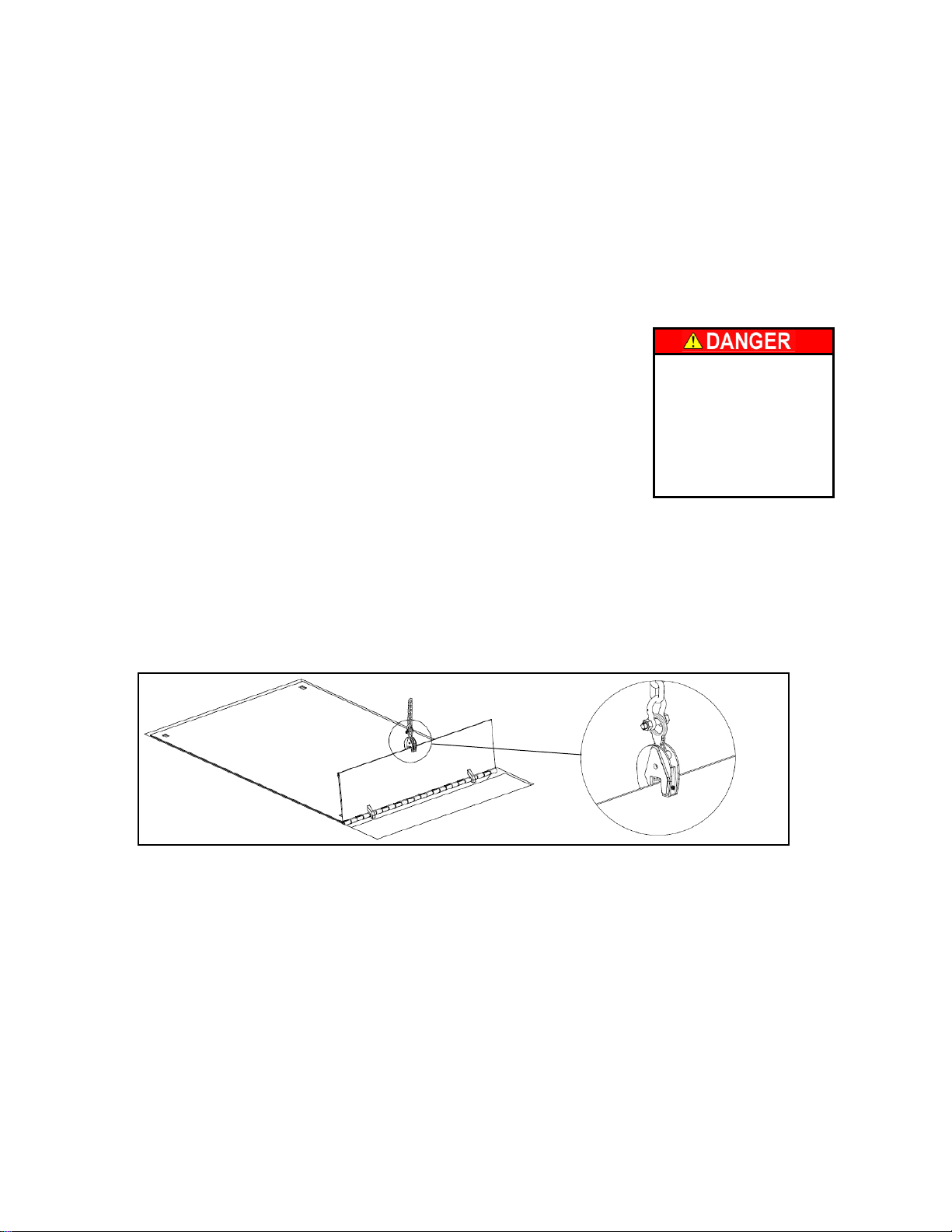
8. You may now break the shipping restraints (banding). Use the lifts power unit to
open the lift a few feet and use your crane to raise the clevis end (hinged bridge
end) of the lift by hooking the bevel toe guard or use a plate grab attached to the
hinged bridge, figure 1. This will allow you to remove your chains or slings and the
banding material from beneath the unit’s base frame. The tipping may not be
necessary if you hooked your lift chains through the guardrail sockets of the platform
and the shipping bands slide out from under the lift.
9. Carefully lower the unit insuring that the platform edges clear the sides of the pit.
The heavy pry bar may be used to reposition the unit with even clearance from all pit
walls. Note the lowered height in relation to the surrounding pit edges for later
shimming adjustments. !The lift shall be installed so that no part of the lift platform is
more than ¼” above or below the surrounding surface.
10.Once the lift is properly positioned, (whether it is pit mounted or surface mounted),
you may begin the lag down procedure. Surface mounted T-Series models have
special lag down instructions located on page P 4-5.
P 4-3
Figure 1

SECTION 4: INSTALLATION INSTRUCTIONS (CONTINUED)
12. Raise the unit and position the maintenance leg or bar as shown in the maintenance
section of this manual (pages 6-3 through 6-7). Lower the unit onto the maintenance
leg and press the down button for an extra 10 seconds to relieve all hydraulic
pressure. Drill the lag down holes and set the lag bolts. Check the unit for side to
side level and then shim or grout the base frame for continuous support. The
shimming should enhance the match between the platform and the surrounding
surfaces when fully lowered, but not at the expense of side to side levelness. A
slight slope from clevis end to roller end is not a problem, but side to side slope will
cause premature wear on all the moving parts of the lift. Tighten the lag bolts.
13. If a temporary hydraulic connection was made to lower the unit into the pit, now is
the time to switch to your permanent hydraulic connection. Note: on T-Series
models the hose must run under the base frame, see page P 4-5 for pit
details. Also, if there are any electrical options such as limit switches or electrical
toe guards, now is the time to do that wiring.
14. Check that there are no tools or debris in the pit or beneath the unit, raise the unit
and remove the maintenance leg, then fully lower the unit. On pit mounted units,
check that the bridges are flush with their curb angles and that they do not pivot
when loads roll over them, shim any movement accordingly.
15. Operate the equipment through several cycles, holding the down button an extra 20
seconds after the lift is fully lowered to bleed air from the cylinders. Check the
reservoir fluid level with the unit fully lowered and top off the fluid to 1” from the top
of the reservoir on 5-gallon reservoirs and 2.5” from the top of 10-gallon reservoirs.
16. Adjust accessories such as limit switches and if the unit has electric toe guards or
roller shades, fasten the hose in the pit so that it does not move and interfere with
proper operation.
17. Raise the unit one final time, install the maintenance leg, and thoroughly clean the
entire area. Be sure all fluid spills are cleaned up so that they are not later
misinterpreted as new fluid leaks. Check all hydraulic fittings for leaks.
18. Meet with the facility manager or maintenance foreman and turn over this
maintenance manual with the reminder that no one should be allowed to operate
the unit unless they are familiar with the operating instructions. Show them the
maintenance leg and any other maintenance devices. Point out the metal nametag
on the unit with the serial number and capacity ratings. Make it clear that some
specific person in their organization must be charged with responsibility for the
maintenance of the unit and if they have no further questions, lower the unit and
consider your job complete.
P 4-4

SECTION 4.1: Special instructions for T - Series Only
Ground Mounted Toe Guards (GMTG)
1. T-Series lifts not installed in pits require additional toe guard protection not outlined
in the previous instructions. The toe guards are placed around the perimeter of the
unit and are used to keep personnel a safe distance from the platform as the unit
raises and lowers. All personnel shall stay to the outside of the toe guards when the
lift is in operation.
2. Place the toe guards 3” from the lift platform’s beveled toe guards as illustrated in
figure 1 below. Insure all four corners line up and lag the guards to the concrete
through the holes provided using 3/8” concrete anchors as shown in figure 2.
3. Units with 8’ platforms require eight (8) concrete anchors and ten (10) anchors are
needed for units over 8’ in length.
4. One of the guards has ¾” drilled mounting holes in it as opposed to the normal ½”
mounting holes. This guard mounts to the base frame “lag-down angle” as illustrated
in figure 3.
P 4-5
Concrete Pad
Ground Mounted
Toe Guard
Lift Platform
(Fig. 1)
Concrete Pad
(Fig. 2)
Ground
Mounted
Toe Guard
Lift Platform
Concrete Anchor
Ground
Mounted
Toe Guard
Lift Platform
(Fig. 3)
Base frame
Angle
Concrete Pad
3”
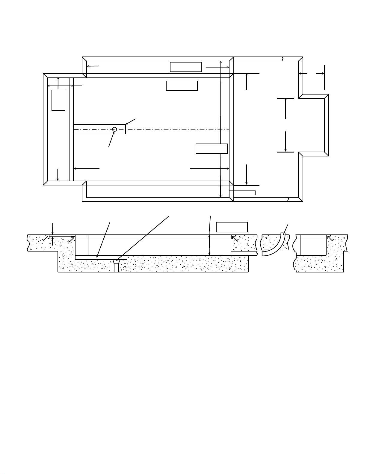
ADVANCE LIFTS PIT DIAGRAM (K’s, T’s, 2000, 3000, & 4000 SERIES)
*When mounting a “T-Series” lift on a pad it is necessary to supply a cutout in the concrete to allow passage of the hose under the
base frame. T-Series lifts have no clearance between the platform and ground, any hose run through or over the base frame will be
damaged when the platform is lowered.
Installation Bill of Material*
1. One (1) Advance Lift Model Number __________.
2. 3” x 3” x ¼” curb angle as required.
3. One (1) 3” conduit from power unit location to pit for hydraulic hose.
4. One (1) electric disconnect switch for 5 HP or 7.5 HP motor.
5. 5 gallons of Chevron Rykon ISO 46 hydraulic fluid for T’s & K’s, 10 gallons for 2000 & 3000 series and 15
gallons for series 4000 units.
6. One (1) ½” SAE 100R2 hydraulic hose from the power unit location to the lift base with ½” female JIC
threads on both ends. (4000 series lifts require two (2) hoses).
7. Concrete anchor bolts and material for shimming and/or grouting.
*Seller furnishes Advance dock lift only unless otherwise agreed to in writing
Notes:
A. Reinforce concrete to suit local soil conditions.
B. All pit work and materials shown are the responsibility of the owner or his agent (by pit contractor)
C. Installer to run ½” diameter hose(s) through the 3” conduit from the power unit to the lift base.
D. Dimension tolerances are plus ¼”, minus 0” (+1/4” – 0).
E. 180º steel hinge bridges require a bridge recess length equal to bridge length minus 2-3/4”.
F. 180º aluminum hinge bridges require a bridge recess length equal to bridge length minus 3-3/4” and a pit
length equal to platform length plus 7-1/2”.
G. Consult factory for bridges longer than 30”. (18” on 4000 series).
P 4-6
16”
PLATFORM LENGTH +2”=
BRIDGE LENGTH MINUS 3-3/4”=
BRIDGE WIDTH + 2”
USE 32” LONG 2X4 LUMBER TO FORM HOSE
RECESS (FOR T-SERIES ONLY)
PIT DRAIN
PLATFORM WIDTH +2”=
PLATFORM LENGTH + 6-1/2”=
(If no bridge, platform length + 2”)
PIT FLOOR MUST BE LEVEL
FOR CASES WHERE BRIDGE
AND PLATFORM ARE THE
SAME WIDTH
50”
PIT CUTOUT FOR
OPTIONAL WHEEL
CHOCK
¾” DEEP BRIDGE
RECESS
T-SERIES HOSE
RECESS
PIT DRAIN
LIFT LOWERED
HEIGHT + ¼”
3” CONDUIT WITH
MINIMUM 14-1/2” RADIUS
BEND

Obstructions and
debris in the pit can
cause the lift to
remain partially
raised above the
surrounding surface
causing a trip
hazard.
SECTION 5:OPERATING INSTRUCTIONS
Hydraulic scissors lifts have an excellent safety record overall, but as with all moving
equipment they can be dangerous. Operators must use common sense and take
responsibility for the safety of everyone near the lift. They must use the devices
provided and be careful not to surprise anyone in the area with the movement of the lift.
The most common accidents that occur are people walking off the end of the lift and
people tripping over the hinged bridge or knocking the bridge over onto someone’s foot.
These are prevented by simply using guardrails and safety chains, and by being aware
of the bridge position and size. Be alert!
Pre-operational checks:
1. Check all electrical wiring and connections to be sure that they are completed
properly and are operational.
2. Check for the proper operating condition of all safety devices such as guardrails,
safety chains, and optional equipment such as electric toe guards, warning bells, or
automatic chocks.
3. Check for obstructions or debris that may interfere with the
safe operation of the lift.
4. Be sure that all personnel in the area are a safe distance
away from the lift and aware that you are about to move
it.
5. Know the capacity of the lift to be sure not to overload it.
Test operate the equipment:
1. Station yourself so that you always see the equipment and surrounding area when it
is in operation. Never operate the equipment in the blind.
2. Raise the equipment and note that the pushbutton is a constant pressure, “dead-
man” type. When you release the up or down button, the unit should stop moving
immediately and maintain its elevation. If it does not, notify your maintenance
personnel immediately.
3. Cycle the equipment several times to be sure that it is operating smoothly with no
jerking or sudden movement. On initial start up there may be some air in the lines or
the cylinders may be dry due to storage so it may take several cycles to smooth out
the operation. If the operation is not smooth after several cycles, contact your
maintenance personnel. If there is any evidence of binding or scraping in the
operation you should immediately stop using the lift.
4. Check all safety devices for proper operation.
5. If you elect to test load the equipment be sure that you do not exceedthe capacities
shown on the nameplate. Overloading may cause structural stresses that may not
show up for some time, but will diminish the life and capacity of the unit. If you have
any questions about testing the unit, call the engineering department at the factory at
1-800-843-3625.
P 5-1

COMPATIBLE LOADING EQUIPMENT GUIDE:
Each Advance lift is designed with a weight capacity and platform design for specific
types of loading equipment. Using the wrong type of loading equipment on a given
series of lifts will invite unintentional overloading. For safe operation, follow these
guidelines and be careful to never exceed the nameplate.
Calculate the weight of the heaviest types of loads you expect to handle to be sure that
they are within the rated capacity. Beware of surprisingly heavy materials such as
liquids, grains, powder, and paper; all of which can weigh much more than you suspect
because of their density.
A little effort to determine the true weight of your heaviest loads before you start to use
your equipment can save damage to your equipment and possible injury to your
personnel. If you discover that some loads will exceed the capacity of the unit, make
arrangements to have the loads split. All operating personnel should be warned about
heavy loads, warning signs should be placed in the dock lift area as a reminder.
Daily operation:
1. All personnel should be required to read the entire operating instruction section of
this manual prior to operating the lift.
2. Operators must know the capacity of the unit and be aware of any loads that may
exceed capacity.
3. Operators must be alert to all personnel in the vicinity of the lift and avoid any
surprises to these personnel in regard to movement of or the position of the lift at
any time. Never operate the unit if you cannot see it and the personnel around it.
4. On the first use of the lift each day, each operator should check to see that the lift is
operating properly and smoothly. All safety devices should be in place and operating
properly and the hinged bridge should be swung through its full arc of movement.
The bridge stops should prevent the bridge from drooping more than 45 degrees
below the horizontal in the forward position and the bridge should swing back 20
degrees beyond vertical toward the platform in the upright position. Any problems
should be immediately reported to the maintenance personnel.
P 5-2
All of the above and small powered
pallet jacks.
2000 SERIES, T & K SERIES
3200 & 3300 SERIES
All of the above & straddle stackers,
small stand-up & sit-down rider fork
trucks.
All of the above & medium fork
trucks.
3400, 3500, 3600 & 4000 SERIES
UNIT
TYPE OF LOADING EQUIPMENT

Daily Operation (Continued)
5. If the unit has a traveling electrical cord, the operator must insure that it is kept away
from the lift as it raises and lowers.
6. When raising or lowering the lift, the load should be centered on the platform (that is,
the load should be evenly distributed and its center of gravity should be at the center
of the platform).
7. If a unit is equipped with both a hinged bridge and a hinged ramp, be sure that the
operators know the difference and never use the ramp for load transfer in the raised
position. The ramps are usually much longer than the bridges which means they
can work as a long lever creating severe eccentric loads and they are often
positioned on the weakest side of the lift for load movement in the fully lowered
position only. Use ramps in the fully lowered position only!
8. Do not allow bridges or ramps to “free fall” from near vertical positions to the position
against their hinge stops. This type of abuse will definitely cause damage to the
stops, hinges, and platform edges, eventually rendering the unit unsafe. Lower
ramps by hand and lower bridges to the down stop position with the restraining
chains.
Efficient lift usage:
The following procedures will help you maximize the efficient use of your lift in your
loading and unloading operations.
1. First it should be noted that there is a long restraining chain on each lift that is
designed to run from the hinged bridge to the guardrail post farthest away from the
bridge. The purpose of this chain is to allow an operator to pull the hinged bridge
back from anywhere on the platform with minimal movement, once the bridge is
raised to the near vertical position by the truck bed as the lift is lowered.
2. This means that the hinged bridge only has to be manually lifted once in a loading or
unloading sequence. It should be raised to the vertical standing position before the
lift is raised to truck height. Once the top of the bridge is just above the truck bed
height, the bridge can be pushed against the truck and allowed to cam into truck.
Then when you lower the unit, the bridge is allowed to cam up on the truck bed to
the near vertical position and then pulled back to a safe resting position with the
chain. There is a second snap on the chain that allows you to lock the bridge in the
raised position whenever the load or guardrails prevents the bridge from swinging
back at least 20º beyond vertical. (See illustration at end of section.)
3. If your unit is equipped with an approach ramp, do not raise the ramp on each cycle.
In fact, the ramp is to be raised only when the lift is being moved to a new location.
Many of the ramps are designed with built in wheel chocks which help prevent a
wheeled vehicle from rolling off the platform and only work properly when the ramp
is lowered.
P 5-3

Placing Bridge in Truck
With bridge folded back toward platform, raise the dock
lift until the top the bridge is just above the opening of the
truck, push the bridge against the truck with your foot
while controlling the fall with the safety chains. As the
dock lift is raised, the bridge will cam over onto the truck
bed and lay flat for loading and unloading.
Removing Bridge from Truck and Securing
Begin to lower the dock lift until the bridge starts to cam
up over the end of the truck bed. With foot, chain, or
hand, flip bridge back toward platform. Once bridge is
folded back toward platform attach Snap Hook (A) to
secure the bridge in place and continue lowering the unit.
Bridge starts to cam up over
end of truck bed as the dock lift
raises or lowers.
How To Use Dock Lifts Efficiently
Palletized Loads: One (1) man removes pallet from
truck, places it in storage area and returns for next
pallet until truck is offloaded.
Non-Palletized Loads: One (1) man in truck stacks
material on pallet or 4-wheeled cars, second man
removes pallet or cart from truck places it in storage
area and returns for nest load until truck is
unloaded.
Objective: Free up the truck as quickly as possible.
•Do not remove bridge stops or allow bridge to hang vertically.
•Shear Hazard

SECTION 6:MAINTENANCE INSTRUCTIONS
The routine maintenance of this equipment is minor and consists of periodic checks.
Weekly: Once a week, or after repetitive operation, the lift operator shall run the lift to
full height. This will get rid of cylinder oil seepage build-up and lubricate the upper
cylinder barrel.
Monthly: Check that the hydraulic fluid level in the reservoir is 1” to 2” from the top of
the tank, depending on model, with the unit fully lowered. It is strongly urged that a
maintenance log be maintained with the dates of monthly inspections, the name of the
inspector and results of the inspection.
Be sure the maintenance device is properly engaged before performing maintenance
checks 2 through 6 or reaching beneath a raised lift. (Read all of section 6 for proper
maintenance safety leg procedures).
1. Clean all debris from the pit or the vicinity of floor mounted units in order to avoid
interference with the lift mechanism or rollers.
2. Check for presence and proper seating of all snap rings and clips on all axles,
cylinders, and rollers.
3. Check rollers, pins and bushings for any signs of wear such as flat spots, missing
fasteners, or dislodged bearing material.
4. Check the hydraulic fittings for cracks or leaks and clean up any seepage on or
beneath the cylinders.
5. Check hoses and electrical lines for abrasions or other abuse and check for snug
connections.
6. Operate the unit and check for any abnormal noise or vibrations.
7. Check all safety devices on the unit such as guardrails, safety chains, etc. including
any options such as electric toe guards or chocks, for proper operation.
8. Check the hinged bridge to insure that its stops are not damaged, allowing it to droop
more than 45 degrees below horizontal, check the hinge spools for cracks and or
broken welds, be sure the bridge leans back over the platform at least 20 degrees
beyond vertical.
Seasonal or semiannual maintenance:
Change hydraulic fluid for ambient temperature changes if appropriate. Check the fluid
reservoir to see if there is any evidence of accumulated condensation creating water
contamination. The fluid will appear “milky” and light pink in color. Water accumulation
will damage the hydraulic pump.
P 6-1

SECTION 6: (CONTINUED)
Maintenance Cautions:
1. Always remember that this is a piece of machinery with large moving parts that can
seriously hurt you.
2. Read this manual in its entirety before attempting service work.
3. Always use the maintenance device if you are going to work on the unit in the
elevated position or reach under the platform. (See the illustrations at the end of this
section for proper positioning and engagement of the maintenance supports.)
4. It may be necessary to bypass travel limit switches in order to properly position the
maintenance support.
5. When using the maintenance support observe the following rules:
A. There shall be no load on the platform
B. The maintenance support shall be properly engaged.
C. Hold the down button an extra 10 seconds when lowering onto the maintenance
support to be sure that all the weight of the lift is on the support.
D. Use shoring of blocking as a backup to the maintenance support.
E. Disconnect and tag the electricity to the unit to prevent accidental movement of
the lift by other personnel.
F. Spend as little time as possible under the lift.
6. Use only replacement parts recommended by the manufacturer.
7. Do not let the equipment stay in disrepair; fix little problems while they are little
problems or some of them may get severe very quickly.
8. Inspect the equipment on a regular schedule, preferably monthly.
9. Never work on the hydraulics or electrical systems unless the unit is fully lowered or
properly sitting on a maintenance device.
10.Never apply a load to the equipment unless the base is continuously supported and
non-portable units are securely lagged to the ground.
11. Never expect to hold leg assemblies open by simply lifting one end of a platform.
A. The roller end of most lifts are not gibbed or captured in any way, so lifting on the
roller end simply tilts the platform.
B. Even if you raise the clevis end of the platform, if the base frame is not firmly
lagged to the ground or held down by some other means, the legs will come up
with the platform in a spongy and unpredictable manner and could cause serious
injury.
C. If the maintenance device is unusable or missing, contact the factory (800-843-
3625) for other methods of blocking the lift up.
P 6-2
Section 6: (Continued)
Recommended Lift Blocking Procedures
This procedure describes the only factory-approved method of working under a lift.
Follow these instructions EVERY time you plan to reach or crawl beneath the lift to
perform service or maintenance – no matter how momentary that might be.
If the factory-provided maintenance device is damaged or missing, stop immediately
and consult the factory for assistance. The manufacturer is not liable for your failure to
use the approved maintenance device(s) and procedures that have been provided.
1. Any load must be removed from the lift prior to engaging the maintenance device(s).
These devices are designed to support an unloaded lift only. Failure to remove the
load from the lift prior to blocking could cause the failure of the maintenance
device(s) and allow the lift to fall unexpectedly. This can result in personal injury or
death, or permanent damage to the maintenance device(s) and/or the lift.
2. Raise the lift to its fully raised position. If you do not, the maintenance device(s) may
not be able to be placed properly in its/their designed blocking position.
3. Remove the maintenance device(s) from its/their storage location and place it/them
into the engaged position as shown on pages P 6-5, P 6-6 & P 6-7. Read and
understand the specific instructions for your model before proceeding.
4. Lower the lift until it makes complete contact with the maintenance device(s). Re-
check to ensure that all provided devices are fully and securely engaged. If the
device(s) is/are not fully engaged the lift could fall unexpectedly, resulting in
permanent damage to the device(s) or the lift.
P 6-3
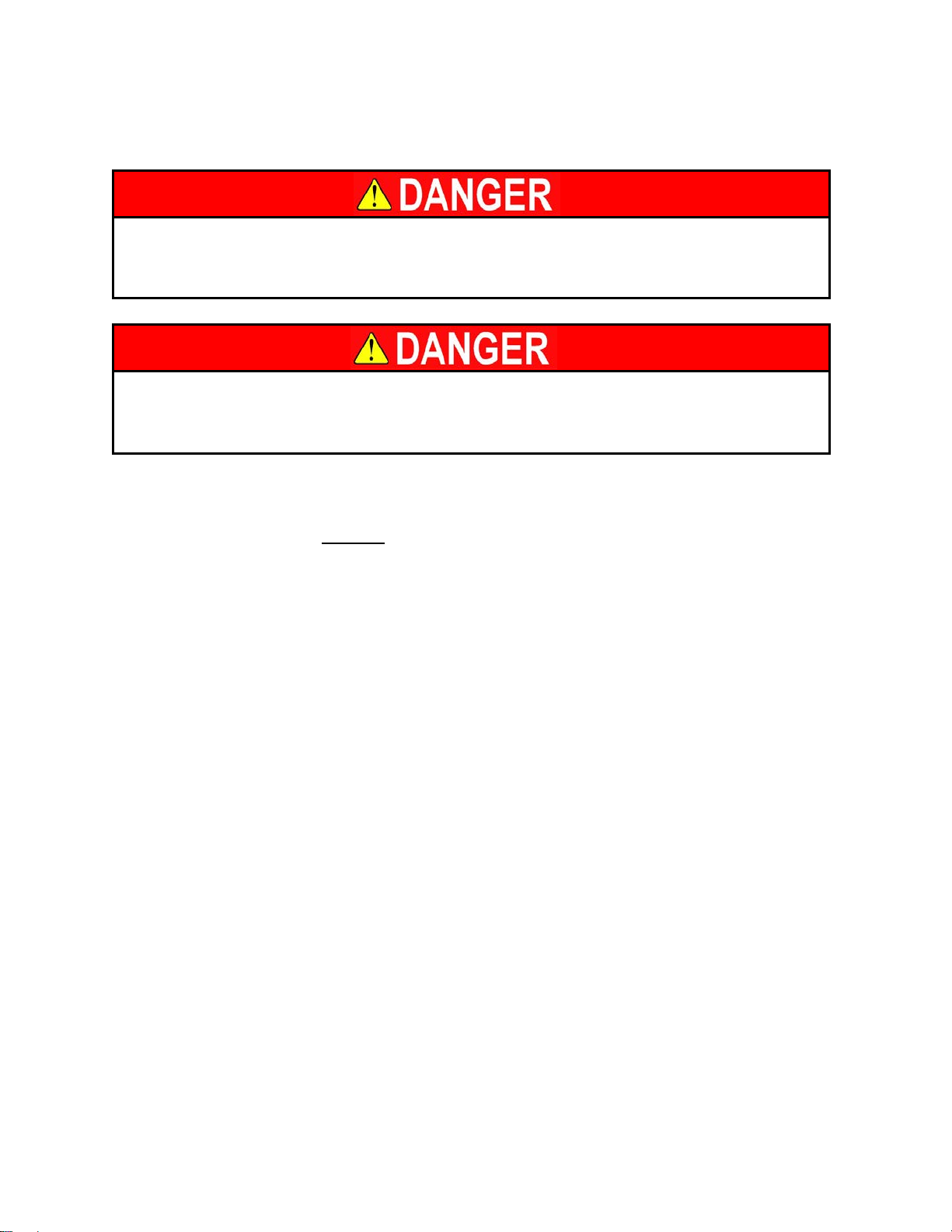
Only authorized personnel should perform inspection or maintenance and
service procedures. Unauthorized personnel attempting these procedures
do so at the risk of severe injury or death.
Failure to properly adhere to lift blocking procedures is to risk the sudden
and uncontrolled descent of the lift during maintenance or inspection. A
falling lift can cause severe injury or death.
This manual suits for next models
116
Table of contents
Other Advance Lifts Lifting System manuals


Popular Lifting System manuals by other brands


Evers
Evers SpanSet ASH 1t Operation manual

Conhersa
Conhersa ET-1000 user manual

Titan Lifts
Titan Lifts PREMIER Series Installation, operation & maintenance manual

Chamberlain
Chamberlain Kinetic Trolley operating instructions

Versalift
Versalift VTL-135-F Operator's manual

BorMann
BorMann PRO BWR5204 manual

Tractel
Tractel Tirfor/greifzug TU-8 Operating and maintenance instruction

Rotary
Rotary VLXS7 installation instructions

S.R.Smith
S.R.Smith PAL2 Series owner's manual

Leguan
Leguan 165 Operator's and service manual

Atlas Equipment
Atlas Equipment 408-SL Super Deluxe Installation & operation manual

Terex
Terex Genie GTH1215M-101 Service and repair manual