Advance Lifts BFL Series User manual

This manual is an important
document. Keep it with the
machine or located where
readily available to operators
and maintenance personnel for
reference purposes.
BFL SERIES LIFTS
Installation, Operation and Maintenance
Manual for the Following Equipment:
All BFL Series Lifts
This manual contains specific information for your equipment, see manual inserts.
In any correspondence with your distributor, you will need the following information:
Model Number______________________ Serial Number_____________________________
Installation location: __________________________________
__________________________________
__________________________________
Distributor Information: ______________________________
_______________________________
_______________________________
Advance Lifts, Inc.
701 S. Kirk Road
St. Charles, IL 60174-3428
Toll Free 1-800-843-3625
Sales Fax 1-630-584-9405
Parts and Service Fax 1-630-584-6837
E-mail: Parts@advancelifts.com
*Advance Lifts, Inc. furnishes one manual with each unit. Additional manuals are available for
$25.00 each.
P 1-1
At Initial Installation, determine proper motor/pump rotation by starting the
motor in very short intervals to prevent permanent pump damage. Running the
pump backwards will damage it. See the Installation Instructions, Section 4, for
proper procedure.

SECTION 2. INDEX & INTRODUCTION
Identification Sheet…………………………………………………………. Section 1
Index & Introduction………………………………………………………… Section 2
*Responsibilities Of Owners & Users….………………..……………….. Section 3
*Installation Instructions……………………………..…………………….. Section 4
*Operation Instructions……………………………………………………… Section 5
*Maintenance Instructions……………………………………………….. … Section 6
*Maintenance Device Placement
Warning Label Specifications & Locations ………………………………. Section 7
Hydraulic Details…………………………………………………………….. Section 8
General hydraulic information
Oil recommendation & seal compatibility
Hydraulic schematic
BFL Series power unit photograph
Hydraulic component lists
BFL Series cylinder drawings and parts lists
Cylinder repair procedures
Electrical Details…………………………………………………………….. Section 9
General electrical information
Electrical schematics
Mechanical Details………………………………………………………….. Section 10
Exploded view and parts descriptions
Spare Parts List
Troubleshooting Hints………………………………………………………. Section 11
Warranty……………………………………………………………………… Section 12
Attachments: Material Safety Data Sheets…………….………………… Section 13
*Mandatory reading before attempting installation.
OPTIONS:
ADVANCE LIFTS ENCLOSURE
ADVANCE LIFTS LANDING LOCKS
P 2-1

SECTION 2. (CONTINUED) INTRODUCTION
Congratulations, the equipment that you have purchased is of the highest quality
available. Advance Lifts industrial scissors lifts are designed and manufactured to
comply with ANSI Standard MH29.1, “Safety Requirements for Industrial Scissors Lifts”.
Your Advance Lift will provide you with many years of trouble free service in return for
the minimal maintenance described in this manual.
Please be sure that no individual is allowed to operate the lift until they have been fully
familiarized with the operating instructions in this manual. Also, insure that at least one
person at the lift site is familiar with the maintenance section of this manual and is
assigned responsibility for doing the maintenance on a regular basis.
Please note that the lift has a metal nameplate attached to it that contains information
such as the model number, capacities, and serial number. Do not remove the
nameplate. Be sure that no operator ever exceeds the capacities shown on the
nameplate or they may injure personnel or cause damage to the lift.
Also, be sure to have the serial number of the lift handy if you have to call your
distributor. That number identifies your specific lift and will allow your distributors
personnel to give you the most thorough and timely assistance possible.
This manual is under constant review and we would appreciate any constructive
suggestions that may enhance its usefulness. Please send your suggestions to
Advance lifts, Inc. Attn: Customer Service Department.
Thank you for purchasing our product.
P 2-2

SECTION 3. RESPONSIBILITIES OF OWNERS & USERS
Basic Principles: Owners/users shall apply sound principles of safety, training, inspection,
maintenance, and expected operating environment.
It shall be the responsibility of the owner/user to advise the manufacturer where deflection may
be critical to the application.
Manuals: Owners/users shall keep and maintain a copy of the operating and maintenance
manual(s) and ensure its availability to operating and maintenance personnel.
Inspection and Maintenance: It shall be the responsibility of the users to inspect and maintain
the industrial scissors lift as required to ensure proper operation. The frequency of inspection
and maintenance shall be based upon the manufacturer’s recommendations and be compatible
with operating conditions and the severity of the operating environment.
Industrial scissors lifts that are not in proper operating condition shall be immediately removed
from service until repaired. Maintenance and repairs shall be made by a qualified person and
the repairs shall be in conformance with the manufacturer’s recommendations.
Maintenance Safety Precautions: Before adjustments and repairs are started on an industrial
scissors lift, the following precautions shall be taken as applicable:
1. Remove the load from the platform.
2. Lower platform to the full down position, if possible or secure by maintenance device
and/or blocking as described by the manufacturer to prevent unintended platform
movement.
3. Relieve system pressure from all circuits before loosening or removing any components.
4. All controls in the “off’ position and all operating features secured from inadvertent
motion by brakes, blocks, or other means.
5. Disconnect power and follow established owner/user lockout/tag out policies.
6. Follow precautions and directions as specified by the manufacturer.
Replacement Parts: When parts or components are replaced, they shall be replaced with parts
or components approved by the original manufacturer of the industrial scissors lift.
Maintenance Training: The owner/user shall ensure only qualified personnel inspect and
maintain the industrial scissors lift in accordance with the sections: Inspection and Maintenance,
Replacement Parts and Operator Training and the manufacturer’s recommendations as
described in the maintenance manual.
Operator Training: An owner/user, who directs or authorizes an individual to operate an
industrial scissors lift, shall ensure that the individual has been:
1. Trained in accordance with the manufacturer’s operating manual.
2. Made aware of the responsibilities of operators as outlined under the Operators Section
of this manual.
3. Retrained, if necessary, based on the owners/user’s observation and evaluation of the
operator.
Modifications: Modifications and additions shall not be performed without the manufacturer’s
prior written approval. Where such authorization is granted, capacity, operation, and
maintenance instruction plates, tags, or decals shall be changed accordingly.
P 3-1

SECTION 3. RESPONSIBILITIES OF OWNERS & USERS (Continued)
Responsibility of Operators
Basic Principles: Operators shall apply sound principles of safety and good judgment in the
application and operation of the scissors lift, with consideration given to its intended use and
expected operating environment. Since the operator is in direct control of the industrial scissors
lift, conformance with good safety practices is the responsibility of the operator. The operator
shall make decisions on the consideration for the fact that his or her own safety as well as the
safety of other personnel on or near the scissors lift is dependent on those decisions.
General Training: Only personnel who have received general instructions regarding the
inspection, application and operation of industrial scissors lifts, including recognition and
avoidance of hazards associated with their operation, shall operate an industrial scissors lift.
Such topics covered shall include, but not necessarily be limited to, the following issues and
requirements:
1. A pre-start inspection
2. Responsibilities associated with problems or malfunctions affecting the operation of the
industrial scissors lift
3. Factors affecting stability
4. The purpose of placards and decals
5. Workplace inspection
6. Safety rules and regulations
7. Authorization to operate
8. Operator warnings and instructions
9. Actual operation of the industrial scissors lift. Under the direction of a qualified person,
the trainee shall operate the industrial scissors lift for a sufficient period of time to
demonstrate proficiency in actual operation of the industrial scissors lift.
Prestart Inspection: Before use each day or at the beginning of each shift, the industrial
scissors lift shall be given a visual inspection and functional test including but not limited to the
following:
1. Operating and emergency controls
2. Safety devices
3. Air or hydraulic system leaks
4. Electrical cables and wiring harness
5. Loose or missing parts
6. Wheels and casters
7. Nameplates, precautionary and instructional markings and/or labeling
8. Guardrail system
9. Items specified by the manufacturer
Problem or Malfunctions: Any problems or malfunctions that affect the safety of operations
shall be repaired prior to the use of the industrial scissors lift.
Before Operations: The operator shall:
1. Read and understand the manufacturer’s operating instruction(s) and user’s safety rules
or have them explained
2. Understand all labels, warnings, and instructions displayed on the industrial scissors lift
or have them explained
P 3-2

SECTION 3. RESPONSIBILITIES OF OWNERS & USERS (Continued)
Responsibility of Operators
Workplace Inspections: Before the industrial scissors lift is used and during use, the operator
shall check the area in which the industrial scissors lift is to be used for possible hazards such
as, but not limited to:
1. Bumps, floor obstructions and uneven surfaces
2. Overhead obstructions and electrical hazards
3. Presence of unauthorized persons
4. Other possible unsafe conditions as noted in the operating manual.
Operator Warnings and Instructions: The operator shall ensure the operation of the industrial
scissors lift is in compliance with the following:
1. Slope. The industrial scissors lift shall only be operated on flat and level surfaces.
2. Guardrail system. Guardrails shall be installed and positioned, and access gates or
openings shall be secured per the manufacturer’s instructions.
3. Distribution of load. The load and its distribution on the platform and any platform
extension(s) shall be in accordance with the manufacturer’s rated capacity for that specific
configuration.
4. Maintaining overhead clearance. The operator shall ensure that adequate clearance is
maintained from overhead obstructions and energized electrical conductors and parts.
5. Point of Operation. The operator shall not place any part of their body under the platform.
6. Personnel footing. Personnel shall maintain firm footing on dock lifts and work access lifts
while working thereon. Climbing by occupants on the guardrail system is prohibited. The use
of planks, ladders, or any other devices on the platform for achieving additional height is
prohibited.
7. Precaution for moving equipment. When other moving equipment or vehicles are
present, special precautions shall be taken to comply with the safety standards established
for the workplace.
8. Reporting problems or malfunctions. The operator shall immediately report to a
supervisor any problem(s) or malfunction(s) that become evident during operation. The
operator shall ensure all problems and malfunctions that affect the safety of operations are
repaired prior to continued use.
9. Capacity limitation. Rated capacity shall not be exceeded when loads are transferred to
the platform at any level.
10. Work area. The operator shall ensure the area surrounding the industrial scissors lift is
clear of personnel and equipment before lowering the platform.
11. Battery charging. Batteries shall be charged in strict accordance with the lift
manufacturer’s instructions.
12. Securing the industrial scissors lift. The operator shall comply with the means and
procedures provided to protect against use by an unauthorized person(s).
13. Altering safety devices. Safety devices shall not be altered or disabled.
14. Modifications. Modifications or alterations of an industrial scissors lift or the fabrication and
attaching of frameworks or the mounting of attachments for holding tools or materials onto
the platform or the guardrail system shall only be accomplished with prior written permission
of the manufacturer.
15. Assistance to the operator. If an operator encounters any suspected malfunction or any
hazard or potentially unsafe condition relating to capacity, intended use or safe operation
the operator shall cease operation of the industrial scissors lift and request further
instruction from the owner/user.
16. Problems or malfunctions. Any problem(s) or malfunction(s) that affect the safety of
operations shall be repaired prior to the use of the industrial scissors lift.
P 3-3

Before securing the unit to
the floor, shim or grout the
entire base frame assembly
to achieve a perfectly level
installation/ if unit is not
level, proper installation is
not possible. Continuous
base frame support is
essential for proper
installation.
SECTION 4. INSTALLATION INSTRUCTIONS
INSTALLATION NOTES:
A. If this job was ordered with Enclosures and/or Landing Locks, read and
understand the accompanying installation manuals for these products before
attempting to install this product.
B. A level and rigid installation is critical to the success of the installation, step #6 of
the installation instructions cannot be overlooked.
C. Some systems are designed with a timed travel function. If lift does not reach the
desired upper or lower targets within the programmed period, the unit will shut
down. Pressing either the up or down button will reset the timer and resume
function. Notice: Continual timing out may damage the pump.
INSTALLATION INSTRUCTIONS:
1. Move the lift to the usage area; insuring the mounting surface is clean and level. If
slings are used, encircle the entire lift, not just the platform. If unit is being lowered
into a pit, make final hose connections before lowering into the pit. See # 2. Note: If
enclosures are used, lift shall be orientated so the Maintenance Devices can be
deployed from the lower enclosure opening without going under the lift.
2. Connect the hydraulic hoses to lift. NOTE: The hoses, valve block and connection
points at the lift are marked with “A”, “B” & “C”. The letters correspond with the
connection points at the power unit. Do not cross hose connections or lift will not
function. Note: if you are using Landing Locks, additional hydraulic connections are
necessary, see Landing Lock Manual.
3. If a pit is being utilized, lower lift into pit and square the unit to the pit using a heavy
pry bar. Be careful with the hoses when lowering lift into pit. Do not cut the steel
bands until the lift is in the final position and no further movement is required.
4. Plug hydraulic power unit into power supply.
Switch the controls to “Maintenance”. Note:
motor will run anytime the controls are switched
to “Maintenance. Using the “Maintenance”
controls raise and lower the unit several times
to begin the air bleeding process. Continued
use will completely remove all air from system.
No other bleeding is necessary. It is
recommended that the power unit be located
within visual range of lift so that any
maintenance operations can be observed when
using the “maintenance mode”.
5. Once unit is in final position, raise unit fully then deploy the maintenance devices.
Lower unit onto devices and lock out the electrical system to disable unit movement.
Follow your companies lock out and tag procedures.
P 4-1

SECTION 4. INSTALLATION INSTRUCTIONS (CONTINUED)
6. Level the unit using steel shims. Shim or grout any portion of the base frame that is
not fully supported by the surface.
7. Lag the unit in place using 3/4” x 6-1/4”, “Rawl-Studs” or wedge anchors in the holes
provided, minimum embedment depth of 3-3/8”.
8. The upper travel target switch is mounted and prewired. The upper travel target
reflector must be field mounted so that the bottom of the reflector is used to signal
the power unit to shut down at the desired raised height.
9. Lower proximity switch mounting hole is located on the base frame near the point
where scissors legs and base frame meet. To set the lowered height, place a metal
straight edge between the base frame structures over the top of the proximity switch.
Insert the proximity switch from below and raise it until it senses the straight edge.
Install the locking nut and tighten.
10.Connect the pushbutton wiring and bi-parting gate wires from the junction box on the
base frame to the control box per the provided schematic.
11.Install pushbutton station(s) if unit is a “Call/Send” and wire to the control box per the
provided schematic.
12.Operate the unit several times making certain the lift stops flush with the upper level.
Adjust the photo eye reflector and test for accuracy, when complete, secure the
reflector.
13.Clean any debris or spilled fluid as they may later be misinterpreted as mechanical
trouble or a cylinder leak. Due to the rigors of shipping it may be necessary to
tighten some hose fittings. Remove maintenance bars and lower the unit.
14.Instruct user(s) in the proper operation of the lift, safety precautions and equipment
capacity. Supply maintenance personnel with this service manual.
P 4-2

SECTION 5. OPERATING INSTRUCTIONS
Hydraulic scissors lifts have an excellent safety record overall, but as with all moving
equipment, they can be dangerous. Operators must use common sense and take
responsibility for the safety of everyone near the lift. They must use the safety devices
provided and be careful not to surprise anyone in the area with the movement of the lift.
Pre-operational checks:
1. Check all electrical wiring and connections to be sure that they are completed
properly and are operational.
2. Check for obstructions or debris that may interfere with the safe operations of the lift.
3. Be sure that all personnel in the area are a safe distance away from the lift and
aware that you are about to operate it.
4. If there are any optional safety devices such as gate interlocks and proximity
switches, check them for proper operation.
Test operate the equipment:
1. Station yourself so that you will always see the equipment when it is in operation.
Never operate the equipment blind!
2. Raise the equipment and by pressing the “UP” and “DOWN” buttons with the unit in
automatic mode or use the “Call/Send” buttons to raise and lower the lift, depending
on the lift configuration.
3. Adjust upper proximity switch to stop platform at desired raised height, if needed.
4. Cycle the equipment several times to be sure that it is operating smoothly with no
jerking or sudden movement. On initial startup, there may be some air in the lines or
the cylinders may be dry due to storage so it may take several cycles to smooth out
the operation. If the operation is not smooth after several cycles, contact your
maintenance personnel. Any evidence of binding or scraping in the operation shall
cause you to immediately stop using the lift.
5. Check all safety devices for proper operation.
6. If you elect to test load the equipment be sure that you do not exceed the capacities
shown on the nameplate. Overloading may cause structural stresses that may not
show up for some time, but will diminish the life and capacity of the unit. If you have
any questions about testing the unit, call our customer service department at 1-800-
843-3625.
Daily operation:
1. All personnel shall be required to read the entire operating instruction section of this
manual prior to operating the lift.
2. Operators must know the capacity of the unit and be aware of any loads that may
exceed the capacity.
P 5-1

SECTION 5. OPERATING INSTRUCTIONS (CONTINUED)
Daily operation (continued):
3. WARNING! Operators must be alert to personnel in the vicinity of the lift. Avoid any
surprises to these personnel in regard to movement of or the position of the lift.
Never operate unit if you cannot see it and the personnel around it.
4. On the first use of the lift each day, the operator shall check to see that the lift is
functioning properly and smoothly. All safety devices shall be in place and operating
correctly.
5. Loads shall be centered before raising or lowering the lift as this will help insure
even wear on all moving parts
P 5-2
Only authorized personnel should perform inspection or maintenance and
service procedures. Unauthorized personnel attempting these procedures
do so at the risk of severe injury or death.
Always use the maintenance device when working under the lift. Failure to
use the maintenance devices properly can result in serious injury or death.
SECTION 6. MAINTENANCE INSTRUCTIONS
1. Always remember that machinery with large moving parts can seriously injure you.
2. Read and understand this manual before attempting any service work.
3. Always use the maintenance device when working on the unit in the elevated
position or reaching under the platform. (See photo on page 6-3, at the end of this
section for proper positioning and engagement of the maintenance device).
4. When using the maintenance device, adhere to the following rules:
A. The unit must be unloaded.
B. Be sure the maintenance devices are properly engaged.
C. Hold the “Maintenance Down” button an extra 10 seconds when lowering onto
the maintenance devices to be sure that all the weight of the lift is on the bars
and hydraulic pressure is relieved.
D. Follow your companies Lock Out/Tag Out procedures to prevent accidental
movement of the lift by other personnel.
E. Spend as little time as possible under the lift.
5. Only use replacement parts recommended by the manufacturer.
6. Do not let the equipment stay in disrepair; fix small problems before they become big
problems. A unit in disrepair can become a severe hazard if left unattended.
7. Inspect the equipment on a regular schedule, preferably monthly.
8. Never work on the hydraulics or electrical systems unless the unit is fully lowered or
properly sitting on the maintenance device.
9. Never apply a load to the equipment until the base frame is continuously supported.
10.Never expect to hold the leg assemblies open by simply lifting one end of a platform.
The only safe way to hold a lift’s legs open is the factory designed maintenance
device.
P 6-1

SECTION 6. MAINTENANCE INSTRUCTIONS (CONTINUED)
Routine Maintenance:
Monthly:
Check the hydraulic fluid level. When checking fluid levels, make sure the unit is fully
lowered. Proper fluid level is 1” from the top of the reservoir.
Be sure the maintenance device(s) are properly engaged before performing
maintenance checks 2 through 6 or reaching beneath a raised lift. (See instructions 3, 4
and 10 above).
1. Clean all debris from the vicinity of floor and pit mounted units in order to avoid
interference with the lift mechanism or rollers.
2. Check for presence and proper seating of all snap rings and clips on all axles,
cylinder and rollers.
3. Check rollers, pins and bushings for any signs of wear such as flat spots, missing
fasteners, or dislodged bearing material.
4. Check the hydraulic fittings for cracks or leaks and clean up any weepage on or
beneath the cylinder.
5. Check hoses and electrical lines for abrasions or other abuse and check for snug
connections.
6. Operate the unit and check for any abnormal noise or vibrations.
Seasonal or Semiannual Maintenance: Advance Lifts recommends that you change
your hydraulic fluid annually. Change hydraulic fluid for ambient temperature change if
appropriate or if there is any evidence of accumulated condensation creating water
contamination. Oil should be changed at least once per year under normal operating
conditions and more frequently in dirty environments or under heavy usage.
P 6-2
Failure to properly adhere to lift blocking procedures is to risk the sudden
and uncontrolled descent of the lift during maintenance or inspection. A
falling lift can cause severe injury or death.
Never use the lift unless the
maintenance devices are
properly stored or they may
be damaged by the scissors
legs.
MAINTENANCE DEVICE INSTRUCTIONS
Always use the maintenance device for any service or maintenance. Never go or reach
under the lift unless both maintenance devices are securely in place and the power to
the unit has been disconnected from its power source to prevent others from operating
the lift. Never use the maintenance device with a load on the platform.
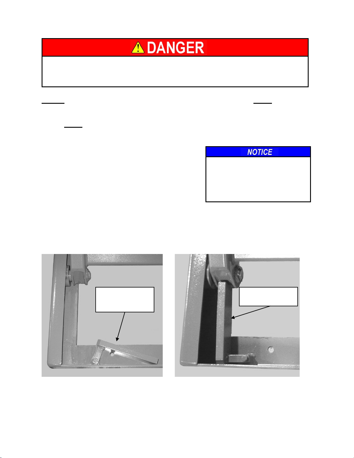
Maintenance Device Usage
1. Rotate maintenance device until they come into
contact with the base frame. Always use both
devices when doing maintenance.
2. Once both bars are in position, lower the unit on
to them. Be certain the devices are positioned
as shown in photo 1-2.
3. Once the unit has been lowered onto the
device, continue pressing the “Down” button to relieve all system pressure making
hydraulic disassembly possible.
4. When storing the maintenance device be certain they are rotated completely as
shown in photo 1-1 or they may be damaged or interfere with the unit collapsing
fully.
P 6-3
MAINTENANCE
DEVICE IN
STORED
MAINTENANCE
DEVICE IN USE
Photo 1-1
Photo 1-2

SECTION 7. REQUIRED IDENTIFICATION AND LABEL PLACEMENT
Label #1 placed on all sides of the platform.
Label #2 placed on all sides of the platform.
P 7-1
Label #3 placed on all sides of the platform.
Label #4 placed on outside of lower leg
assemblies.
Label #5 placed
on guardrail
uprights.
#6 Advance Lifts identification and data plate.
Data plate located on side of platform.
CAPACITY
LABELS
placed on
all sides of
the
platform.
4
5
3
2
1
6
Failure to relieve operating system pressure could result in the sudden and
unexpected release of high-pressure fluids (or air) during maintenance and/or
repair of the lift and result in severe injury or death.
SECTION 8. HYDRAULIC DETAILS
1. General Hydraulic Information
A. Over time, all hydraulic cylinders will require replacement seals depending on
usage and environmental conditions. Seal wear and replacement is normal
maintenance.
B. Always be careful when working around cylinders, not to nick the extended rod or
dent the cylinder casing, as this may cause damage to cylinder seals.
C. If you elect to repaint any part of the lift, cover exposed rods with plastic or
soluble grease, which can be removed after painting to insure that no paint sticks
to the rods and damages the seals.
2. General precautions:
A. Be sure that all pressure is relieved from the hydraulic system before
disassembling any components. Continue to hold the “Maintenance Down”
control for several seconds after fully lowering the unit on its maintenance device
or the ground, before opening a hose line or hydraulic component.
B. Always be careful to avoid contamination entering the system. Be especially
careful with the ends of hoses, which may fall into oil dry, or dirt. If you suspect
contamination, flush the system and components.
3. Hydraulic fittings, sealant and torque’s:
A. Advance Lifts may be equipped with either NPT fittings (tapered), or SAE fittings
(with O-ring seals), or JIC fittings (37˚ flare). None of these fittings are
interchangeable, know the difference.
B. Be careful when tightening NPT fittings not to over-tighten and crack them.
Swivel fittings are especially vulnerable and shall only be tightened enough to
stop leaking.
C. If leakage persists after tightening the fittings fairly hard, inspect fittings for burrs
on the mating edges or replace the fitting.
D. When using Teflon tape on NPT fittings, be sure the tape is started 1-1/2 threads
back from the leading edge and only use 2 wraps to be sure that tape does not
break off and contaminate the system. You may substitute pipe sealant with
Teflon paste from “Pro Lock” or “Loctite”, but again do not over apply. Never use
sealant or tapes on JIC, or SAE O-ring fittings.
E. Be extremely careful not to over-tighten SAE fittings, thread the fitting finger tight
and then tighten the nut on the fitting.
F. Never reuse old Teflon tape. Once a connection has been opened, remove all
tape and apply fresh tape.
P 8-1

OIL RECOMMENDATIONS AND SEAL COMPATIBILITY
Fluids:
1. The current standard hydraulic fluid is a multi-viscosity ISO-46 group II base oil
hydraulic fluid. This is the fluid normally supplied by the factory and is suitable for a
temperature range of –10 to +100 degrees Fahrenheit. When replacing or adding
fluid to an Advance Lift, use only ISO 46 hydraulic fluid that is manufactured with a
group II base oil.
2. Unless approved by the Advance lifts engineering department do not use any other
fluid. Brake fluids and other hydraulic fluids may damage the system’s seals or
hoses. If it is required to switch from one fluid to another, drain the reservoir and
system completely, and then refill with the new fluid.
3. Biodegradable and fire retardant fluids are available. Contact the factory for
specifications. It may be necessary to change some seals and/or hoses for total
system compatibility, depending upon the specific model lift and the requested fluid.
Options:
For oil options, contact the factory, 800-843-3625.
Seals:
Generally, the seals in the unit are Buna-N-Nitrile and polyurethane. The hoses are
either PVC for suction lines or braided wire for pressure lines. Always call the factory
about special fluids rather than make assumptions on your own.
P 8-2
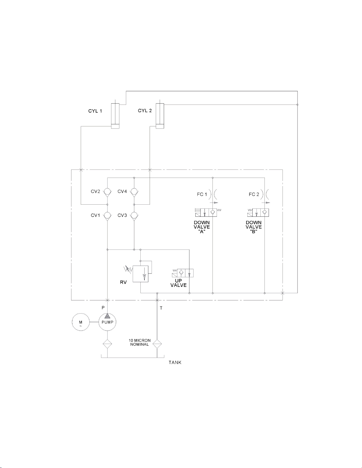
HYDRAULIC SCHEMATIC
P 8-3
MOTOR
RESERVOIR

BFL SERIES CYLINDER
P 8-4
ROD
BEARING
HOUSING
PISTON
RETAINING
NUT
HOSE
CONNECTION
WEAR RING
WEAR
RING
STATIC
SEAL
PISTON
SEAL
ROD
SEAL
O-RING
SEAL
ROD
WIPER
RETAINING
CLIP
BEARING

Cylinder Removal Procedure for BFL-Series Lifts
Tools & Supplied required:
Factory recommended hydraulic fluid
Snap-ring pliers
Hammer
Drift pin
Cylinder Removal, BFL-Series units:
NOTE: Some BFL-Series cylinders can weigh in excess of 500lbs. great care
should be taken when removing cylinders.
1. Raise the empty lift and settle it securely on its maintenance devices. See page P 6-
3 for proper lift blocking.
2. Once settled securely, depress the “Maintenance Down” control an additional 20
seconds to relieve any pressure from the hydraulic system. Disconnect the electrical
supply following your companies Lock Out/Tag Out procedures.
3. Disconnect the hydraulic hoses from the cylinder and plug the hose to prevent
contamination.
4. Secure the cylinder with a web sling connected to the structure. Remove the lower
pin and remove the cylinder from the scissors legs. On larger units or units with a
heavy lifting capacity, secure the web sling to a chain hoist from above. Note: It may
be necessary to weld a chain hook to the underside of the platform to achieve this.
On very large units, it may be necessary to remove the platform prior to removing
the cylinder. Call the factory with any questions concerning your particular unit, 800-
843-3625.
5. Carefully remove the lower pin and using the chain hoist, lower the cylinder to the
ground
6. Place the hose connection end of the cylinder in a 5-gallon bucket and force the
cylinder closed to drain the hydraulic fluid from the cylinder. Do not reuse the fluid
unless you are sure it is contamination free by careful straining.
Cylinder Repair:
All Advance Lifts cylinders use a high grade two-piece seal design comprised of a
standard size O-ring with a glass-filled PTFE cap. These seals are not replaceable in
the field without specialized tools. Advance recommends that you consult with a
professional who has the necessary tools to install the seals.
P 8-5
Table of contents
Other Advance Lifts Lifting System manuals


Popular Lifting System manuals by other brands


WALTCO
WALTCO GT-33 installation manual

OMCR
OMCR B01.24 Use and maintenance manual

ATLAS PLATINUM
ATLAS PLATINUM PVL14OF-EXT Installation & operation manual

Duarib
Duarib Altitude 150 Assembly, Disassembly and Use Instructions

Scaleo medical
Scaleo medical Poweo 200 user manual

Braun
Braun RA300 Operator, Installation, Service Manual


