Advansus DS3630-945GSE User manual

DS3630-945GSE
Intel® 945GSE Supports Intel® FCBGA8 45nm Atom™ N270
Processor Mini ITX Main Board
User’s Manual
Ver. 1.00
Free Datasheet http://www.Datasheet4U.com

DS3630-945GSE
2 DS3630-945GSE User’s Manual
Contents
Notices................................................................................................................................4
Safety information .............................................................................................................5
About this guide ................................................................................................................6
Typography........................................................................................................................7
DS3630-945GSE specifications summary .......................................................................8
1.1 Welcome!....................................................................................................................10
1.1 Welcome!....................................................................................................................11
1.2 Package contents ......................................................................................................11
1.3 Special features .........................................................................................................12
1.3.1 Product highlights .....................................................................................................12
1.4 Before you proceed...................................................................................................14
1.5 Motherboard overview...............................................................................................15
1.5.1 Placement Direction..................................................................................................15
1.5.2 Screw Holes..............................................................................................................15
1.5.3 Motherboard Layout..................................................................................................16
1.6 System memory.........................................................................................................17
1.6.1 Overview...................................................................................................................17
1.6.2 Memory Configurations.............................................................................................17
1.6.3 Installing a DIMM......................................................................................................18
1.6.4 Removing a SO-DIMM..............................................................................................18
1.7 Expansion slots .........................................................................................................18
1.7.1 Installing an Expansion Card....................................................................................19
1.7.2 Configuring an Expansion Card................................................................................19
1.7.3 PCI slots ...................................................................................................................19
1.8 Jumpers......................................................................................................................20
1. Clear RTC RAM (CLRTC)..............................................................................................20
2. COM1 RI, +12V and +5V Power Select (JCOMPWR1, JCOMPWR2)...........................21
3. COM2 RI, +12V and +5V Power Select (JCOMPWR1, JCOMPWR2)...........................21
4. COM3 RI, +12V and +5V Power Select (JCOMPWR3, JCOMPWR4)...........................22
5. COM4 RI, +12V and +5V Power Select (JCOMPWR3, JCOMPWR4)...........................22
6. System Panel Connector (F_PANEL1)..........................................................................23
1.9 Connectors.................................................................................................................24
1.9.1 Rear panel connectors..............................................................................................24
1.9.2 Internal connectors ...................................................................................................25
2.1 Managing and updating your BIOS .....................................................................34
2.1.1 Creating a bootable floppy disk ...........................................................................34
Free Datasheet http://www.Datasheet4U.com

User’s Manual
DS3630-945GSE User’s Manual
3
2.2 BIOS setup program..................................................................................................35
2.2.1 Legend Box .........................................................................................................36
2.2.2 List Box................................................................................................................36
2.2.3 Sub-menu............................................................................................................36
2.3 BIOS menu screen.....................................................................................................37
2.3.1 Standard CMOS Features...................................................................................38
2.3.2 Advanced BIOS Features....................................................................................40
2.3.3 Advanced Chipset Features ................................................................................45
2.3.4 Integrated Peripherals.........................................................................................47
2.3.5 Security Chip Configuration.................................................................................52
2.3.6 Power Management Setup..................................................................................53
2.3.7 PnP/PCI Configurations.......................................................................................55
2.3.8 PC Health Status.................................................................................................56
2.3.9 Frequency/Voltage Control..................................................................................57
2.3.10 Load Optimized Defaults.....................................................................................58
2.3.11 Set Supervisor Password ....................................................................................59
2.3.12 Set User Password..............................................................................................60
2.3.13 Save & Exit Setup................................................................................................61
2.3.14 Exit Without Saving .............................................................................................62
Free Datasheet http://www.Datasheet4U.com

DS3630-945GSE
4 DS3630-945GSE User’s Manual
Notices
Federal Communications Commission Statement
This device complies with Part 15 of the FCC Rules. Operation is subject to the following
two conditions:
yThis device may not cause harmful interference, and
yThis device must accept any interference received including interference that may
cause undesired operation.
This equipment has been tested and found to comply with the limits for a Class B digital
device, pursuant to Part 15 of the FCC Rules. These limits are designed to provide
reasonable protection against harmful interference in a residential installation. This
equipment generates, uses and can radiate radio frequency energy and, if not installed and
used in accordance with manufacturer’s instructions, may cause harmful interference to
radio communications. However, there is no guarantee that interference will not occur in a
particular installation. If his equipment does cause harmful interference to radio or
television reception, which can be determined by turning the equipment off and on, the user
is encouraged to try to correct the interference by one or more of the following measures:
yReorient or relocate the receiving antenna.
yIncrease the separation between the equipment and receiver.
yConnect the equipment to an outlet on a circuit different from that to which the receiver
is connected.
yConsult the dealer or an experienced radio/TV technician for help.
The use of shielded cables for connection of the monitor to the
graphics card is required to assure compliance with FCC
regulations. Changes or modifications to this unit not expressly
approved by the party responsible for compliance could void the
user’s authority to operate this equipment.
Canadian Department of Communications Statement
This digital apparatus does not exceed the Class B limits for radio noise emissions from
digital apparatus set out in the Radio Interference Regulations of the Canadian Department
of Communications.
This class B digital apparatus complies with Canadian ICES-003.
Free Datasheet http://www.Datasheet4U.com

User’s Manual
DS3630-945GSE User’s Manual
5
Safety information
Electrical safety
yTo prevent electrical shock hazard, disconnect the power cable from the electrical
outlet before relocating the system.
yWhen adding or removing devices to or from the system, ensure that the power cables
for the devices are unplugged before the signal cables are connected. If possible,
disconnect all power cables from the existing system before you add a device.
yBefore connecting or removing signal cables from the motherboard, ensure that all
power cables are unplugged.
ySeek professional assistance before using an adapter or extension cord. These
devices could interrupt the grounding circuit.
yMake sure that your power supply is set to the correct voltage in your area.
yIf you are not sure about the voltage of the electrical outlet you are using, contact your
local power company.
yIf the power supply is broken, do not try to fix it by yourself. Contact a qualified service
technician or your retailer.
Operation safety
yBefore installing the motherboard and adding devices on it, carefully read all the
manuals that came with the package.
yBefore using the product, make sure all cables are correctly connected and the power
cables are not damaged. If you detect any damage, contact your dealer immediately.
yTo avoid short circuits, keep paper clips, screws, and staples away from connectors,
slots, sockets and circuitry.
yAvoid dust, humidity, and temperature extremes. Do not place the product in any area
where it may become wet.
yPlace the product on a stable surface.
yIf you encounter technical problems with the product, contact a qualified service
technician or your retailer.
The symbol of the crossed out wheeled bin indicates that the
product (electrical and electronic equipment) should not be placed
in municipal waste. Check local regulations for disposal of
electronic products.
Free Datasheet http://www.Datasheet4U.com

DS3630-945GSE
6 DS3630-945GSE User’s Manual
About this guide
This user guide contains the information you need when installing and configuring the
motherboard.
How this guide is organized
This manual contains the following parts:
yChapter 1: Product introduction
This chapter describes the features of the motherboard and the new technology it
supports. This chapter also lists the hardware setup procedures that you have to
perform when installing system components. It includes description of the jumpers and
connectors on the motherboard.
yChapter 2: BIOS setup
This chapter tells how to change system settings through the BIOS Setup menus.
Detailed descriptions of the BIOS parameters are also provided.
Where to find more information
Refer to the following sources for additional information and for product and software
updates.
1. Advansus websites
The Advansus website provides updated information on Advansus hardware and software
products. Refer to the Advansus contact information.
2. Optional documentation
Your product package may include optional documentation, such as warranty flyers, that
may have been added by your dealer. These documents are not part of the standard
package.
Conventions used in this guide
To make sure that you perform certain tasks properly, take note of the following symbols
used throughout this manual.
DANGER/WARNING: Information to prevent injury to yourself
when trying to complete a task.
CAUTION: Information to prevent damage to the components
when trying to complete a task.
IMPORTANT: Instructions that you MUST follow to complete a
task.
NOTE: Tips and additional information to help you complete a
task.
Free Datasheet http://www.Datasheet4U.com

User’s Manual
DS3630-945GSE User’s Manual
7
Typography
Bold text Indicates a menu or an item to select
Italics Used to emphasize a word or a phrase
<Key> Keys enclosed in the less-than and greater-than sign means
that you must press the enclosed key
Example: <Enter> means that you must press the Enter or
Return key
<Key1>+<Key2>+<Key3> If you must press two or more keys simultaneously, the key
names are linked with a plus sign (+)
Example: <Ctrl>+<Alt>+<D>
Command Means that you must type the command exactly as shown,
then supply the required item or value enclosed in brackets
Example: At the DOS prompt, type the command line:
afudos /i[filename]
afudos /iP5P800VM.ROM
Free Datasheet http://www.Datasheet4U.com

DS3630-945GSE
8 DS3630-945GSE User’s Manual
DS3630-945GSE specifications summary
Specifications
System
CPU Supports Intel® FCBGA8 45nm Atom™ N270 Processor
FSB 533 MHz
BIOS Award 4MB (Mega Byte) SPI BIOS
System Chipset Intel® 945GSE + ICH7-M Chipset
I/O Chipset Winbond W83627DHG-A
Memory One 200-pin SO-DIMMs up to 2GB single Channel DDR2 533 SDRAM ,
non-ECC
SSD One CompactFlash Type I/II socket
Watchdog Timer Reset: 1 sec.~255 min. and 1 sec. or 1 min./step
H/W Status Monitor Monitoring CPU temperature, voltage, and cooling fan status. Auto throttling
control when CPU overheats
Expansion Slots 1 x PCI (PCI Rev. 2.3 compliant) supports 3 PCI master
DIO 8-bit General Purpose I/O for DI and DO
S3/S4 Yes
TPM TPM1.2 (Infineon® TPM chip 9635 TT 1.2 on board)LAN (PME / RPL)
Wake up on LAN or Ring YES
Display
Chipset Intel® 945GSE GMCH integrated Graphics Media Accelerator 950
Display Memory Intel® DVMT 3.0 supports 224 MB video memory
Max Resolution CRT mode :2048x1536@75Hz , LCD mode : 2048x1536@60Hz
Dual Display Dual view, 2-CH LVDS, DVI
VGA Yes , on board GMA 950,Support for CRT resolutions up to QXGA
LVDS Support for dual-channel LVDS resolutions up to UXGA
18bit Single/Dual channel
LVDS Backlight power
connector Yes
DVI Yes
Networking
LAN1 Realtek RTL8111C Gigabit LAN
LAN2 Realtek RTL8111C Gigabit LAN
Audio
Audio Codec Realtek® ALC888, 5.1 HD Audio
Audio Interface Mic in, Line in, Line out
Audio Amplifier (W) TPA3005D2 Stereo 6Watt
Free Datasheet http://www.Datasheet4U.com

User’s Manual
DS3630-945GSE User’s Manual
9
I/O Port
Back Panel I/O Port 1 x PS/2 Keyboard, 1 x PS/2 Mouse, 1 x VGA port, 1 x DVI port, 2 x COM Port,
2 x RJ45 port, 4 x USB 2.0/1.1, 1 x Audio Jack (3 ports)
Internal I/O
2 x Power COM port, 1 x 2x10-pin ATX power connector, 1 x CPU fan
connector, 1 x Power fan connector, 1 x USB connectors support additional 2
USB ports, 1 x LVDS connector, 1 x LVDS inventor connector, 1 x IDE
connector, 2 x SATA connectors, 1 x Digital IO header, 1 x Front panel header,
1 x S/PDIF Out header, 1 x Audio amplifier connector, 1 x Front audio
connector, 1 x Mini-PCI Express
Mechanical & Environment
Power Type ATX mode
Operating Temp. 0 ~ 60℃(32 ~ 140℉)
Operating Humidity 0%~90% relative humidity, non-condensing
Size (L x W) 170 mm x 170 mm
* Specifications are subject to change without notice.
Free Datasheet http://www.Datasheet4U.com

DS3630-945GSE
10 DS3630-945GSE User’s Manual
1
This chapter describes the
motherboard features and the
new technologies it supports.
Product
Introduction
Free Datasheet http://www.Datasheet4U.com

User’s Manual
DS3630-945GSE User’s Manual
11
1.1 Welcome!
Thank you for buying an ® DS3630-945GSE motherboard!
The motherboard delivers a host of new features and latest technologies, making it another
standout in the long line of quality motherboards!
Before you start installing the motherboard, and hardware devices on it, check the items in
your package with the list below.
1.2 Package contents
Check your motherboard package for the following items.
Before you begin installing your single board, please make sure that the following materials
have been shipped:
z1 x DS3630-945GSE Mini ITX Main board
z1 x CD-ROM contains the followings:
•User’s Manual in PDF file
•Drivers
z1 x IDE cable (40-pin)
z2 x SATA cable kit (SATA/Power)
z1 x I/O Shield
z1 x Startup Manual
If any of the above items is damaged or missing, contact your
retailer.
Free Datasheet http://www.Datasheet4U.com

DS3630-945GSE
12 DS3630-945GSE User’s Manual
1.3 Special features
1.3.1 Product highlights
The Latest Processor Technology
The Intel® Atom™ processor is Intel's smallest processor, built with the world's smallest
transistors and manufactured on Intel's industry-leading 45nm Hi-k Metal Gate technology.
The Intel Atom processor was purpose-built for simple, affordable, netbooks and nettops.
Intel® Atom™ N270 Processor
The Intel® Atom™ processor N270, implemented in 45nm technology, is power-optimized
and delivers robust performance-per-watt for cost-effective embedded solutions. Featuring
extended lifecycle support, this processor offers an excellent solution for embedded market
segments such as digital signage, interactive clients (kiosks, point-of-sale terminals), thin
clients, digital security, residential gateways, print imaging, and commercial and industrial
control. The processor remains software compatible with previous 32-bit Intel® architecture
and complementary silicon.
Intel® 945GSE Chipset
The mobile Intel® 945GSE Express Chipset provides power-efficient graphics and rich I/O
capabilities for cost-effective embedded solutions. It features an integrated 32-bit 3D
graphics engine based on Intel® Graphics Media Accelerator 950 (Intel® GMA 950)
architecture, a 533 MHz front-side bus (FSB), single-channel 400/533 MHz DDR2 system
memory (SODIMM and/or memory down), and Intel® High Definition Audio¹ interface.
The chipset consists of the Intel® 82945GSE Graphics Memory Controller Hub (GMCH)
and Intel® I/O Controller Hub 7-M (ICH7-M). It delivers outstanding system performance
and flexibility through high-bandwidth interfaces such as PCI Express,* PCI, Serial ATA,
and Hi-Speed USB 2.0 connectivity.
DDR2 memory support
The motherboard supports DDR2 memory which features data transfer rates of
1066/800/533 MHz to meet the higher bandwidth requirements of the latest 3D graphics,
multimedia, and Internet applications. The dual-channel DDR2 architecture doubles the
bandwidth of your system memory to boost system performance, eliminating bottlenecks
with peak bandwidths of up to 8.5 GB/s.
PCI Express™ interface
The motherboard fully supports PCI Express, the latest I/O interconnect technology that
speeds up the PCI bus. PCI Express features point‑to‑point serial interconnections
between devices and allows higher clockspeeds by carrying data in packets. This high
Free Datasheet http://www.Datasheet4U.com

User’s Manual
DS3630-945GSE User’s Manual
13
speed interface is software compatible with existing PCI specifications. See page 1-22 for
details.
Serial ATA technology
The motherboard supports the Serial ATA technology through the Serial ATA interfaces
and the Intel® ICH7 chipset. The SATA specification allows for thinner, more flexible cables
with lower pin count, reduced voltage requirement, and up to 300 MB/s data transfer rate.
S/PDIF digital sound ready
The motherboard supports the S/PDIF Out function through the S/PDIF interfaces at
mainboard. The S/PDIF technology turns your computer into a high-end entertainment
system with digital connectivity to powerful audio and speaker systems. See page 1-31 for
details.
Temperature, fan, and voltage monitoring
The CPU temperature is monitored by the ASIC (integrated in the Winbond Super I/O) to
prevent overheating and damage. The system fan rotations per minute (RPM) is monitored
for timely failure detection. The ASIC monitors the voltage levels to ensure stable supply of
current for critical components.
Free Datasheet http://www.Datasheet4U.com

DS3630-945GSE
14 DS3630-945GSE User’s Manual
1.4 Before you proceed
Take note of the following precautions before you install motherboard components or
change any motherboard settings.
yUnplug the power cord from the wall socket before touching
any component.
yUse a grounded wrist strap or touch a safely grounded object
or a metal object, such as the power supply case, before
handling components to avoid damaging them due to static
electricity
yHold components by the edges to avoid touching the ICs on
them.
yWhenever you uninstall any component, place it on a
grounded antistatic pad or in the bag that came with the
component.
yBefore you install or remove any component, ensure that
the ATX power supply is switched off or the power cord is
detached from the power supply. Failure to do so may
cause severe damage to the motherboard, peripherals, and/or
components.
Free Datasheet http://www.Datasheet4U.com
User’s Manual
DS3630-945GSE User’s Manual
15
1.5 Motherboard overview
Before you install the motherboard, study the configuration of your chassis to ensure that
the motherboard fits into it.
Make sure to unplug the power cord before installing or removing
the motherboard. Failure to do so can cause you physical injury and
damage motherboard components.
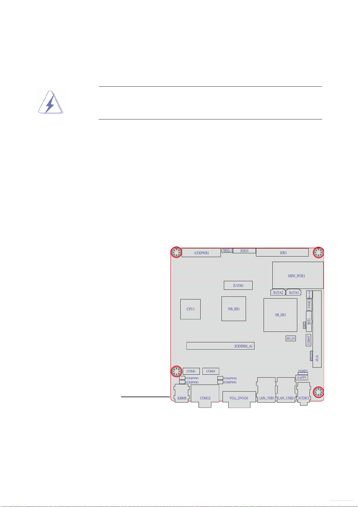
1.5.1 Placement Direction
When installing the motherboard, make sure that you place it into the chassis in the correct
orientation. The edge with external ports goes to the rear part of the chassis as indicated in
the image below.
1.5.2 Screw Holes
Place four (4) screws into the holes indicated by circles to secure the motherboard to the
chassis.
Place this side towards
the rear of the chassis
Free Datasheet http://www.Datasheet4U.com
DS3630-945GSE
16 DS3630-945GSE User’s Manual
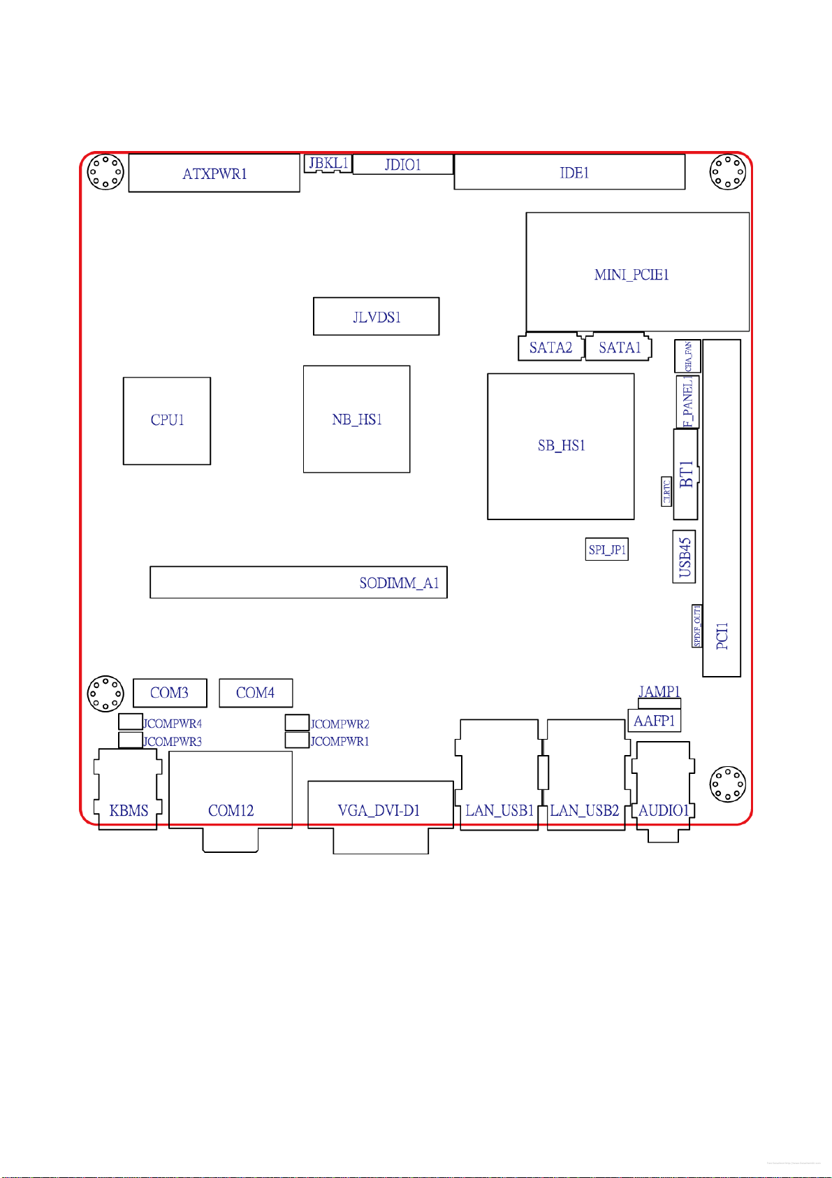
1.5.3 Motherboard Layout
Free Datasheet http://www.Datasheet4U.com

User’s Manual
DS3630-945GSE User’s Manual
17
1.6 System memory
1.6.1 Overview
The motherboard comes with one 200-pin Double Data Rate 2 (DDR2) Small Outline Dual
Inline Memory Modules (SO-DIMM) sockets.
A DDR2 module has the same physical dimensions as a DDR DIMM but has a 200-pin
footprint compared to the 184-pin DDR DIMM. DDR2 DIMMs are notched differently to
prevent installation on a DDR DIMM socket. The following figure illustrates the location of
the sockets:
200-Pin DDR2 SO-DIMM sockets
Channel Socket
Channel A SO DIMM_A1
1.6.2 Memory Configurations
You may install 64 MB, 128 MB, 256 MB, 512 MB and 1 GB unbuffered ECC or non-ECC
DDR SO-DIMMs into the SO-DIMM sockets using the memory configurations in this
section.
Free Datasheet http://www.Datasheet4U.com

DS3630-945GSE
18 DS3630-945GSE User’s Manual
1.6.3 Installing a DIMM
Make sure to unplug the power supply before adding or removing
SO-DIMMs or other system components. Failure to do so may cause
severe damage to both the motherboard and the components.
1. Unlock a SO-DIMM socket by pressing the retaining clips outward
2. Align a SO-DIMM on the socket such that the notch on the SO-DIMM matches the
break on the socket.
3. Firmly insert the SO-DIMM into the socket until the retaining clips snap back in place
and the SO-DIMM is properly seated.
zA DDR2 SO-DIMM is keyed with a notch so that it fits in only one
direction. DO NOT force a SO-DIMM into a socket to avoid
damaging the SO-DIMM.
zThe DDR2 SO-DIMM sockets do not support DDR SO-DIMMs. DO
NOT install DDR SO-DIMMs to the DDR2 SO-DIMM socket.
1.6.4 Removing a SO-DIMM
1. Simultaneously press the retaining clips outward to unlock the SO-DIMM.
Support the SO-DIMM lightly with your fingers when pressing the
retaining clips. The SO-DIMM might get damaged when it flips out with
extra force.
2. Remove the SO-DIMM from the socket.
1.7 Expansion slots
In the future, you may need to install expansion cards. The following sub-sections describe
the slots and the expansion cards that they support.
Make sure to unplug the power cord before adding or removing
expansion cards. Failure to do so may cause you physical injury and
damage motherboard components.
Free Datasheet http://www.Datasheet4U.com
User’s Manual
DS3630-945GSE User’s Manual
19
1.7.1 Installing an Expansion Card
1. Before installing the expansion card, read the documentation that came with it and
make the necessary hardware settings for the card.
2. Remove the system unit cover (if your motherboard is already installed in a chassis).
3. Remove the bracket opposite the slot that you intend to use. Keep the screw for later
use.
4. Align the card connector with the slot and press firmly until the card is completely seated
on the slot.
5. Secure the card to the chassis with the screw you removed earlier.
6. Replace the system cover.
1.7.2 Configuring an Expansion Card
After installing the expansion card, configure it by adjusting the software settings.
1. Turn on the system and change the necessary BIOS settings, if any. See Chapter 2 for
information on BIOS setup.
2. Assign an IRQ to the card if needed. Refer to the tables on the next page.
3. Install the software drivers for the expansion card.
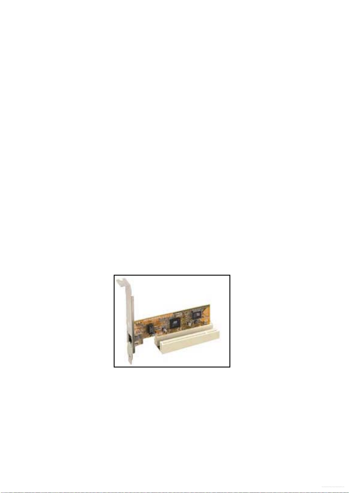
1.7.3 PCI slots
The PCI slots support cards such as a LAN card, SCSI card, USB card, and other cards
that comply with PCI specifications. The figure shows the type of LAN card that can be
installed on a PCI slot.
Free Datasheet http://www.Datasheet4U.com
DS3630-945GSE
20 DS3630-945GSE User’s Manual
1.8 Jumpers
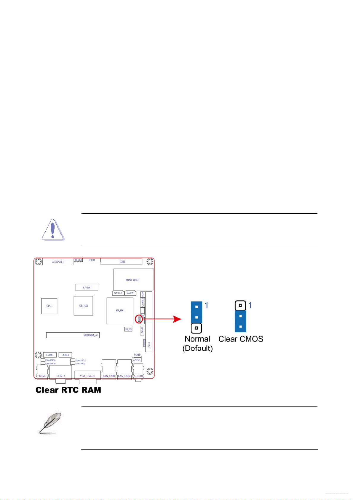
1. Clear RTC RAM (CLRTC)
This jumper allows you to clear the Real Time Clock (RTC) RAM in CMOS. You can clear
the CMOS memory of date, time, and system setup parameters by erasing the CMOS RTC
RAM data. The onboard button cell battery powers the RAM data in CMOS, which include
system setup information such as system passwords.
To erase the RTC RAM:
1. Turn OFF the computer and unplug the power cord.
2. Remove the onboard battery.
3. Move the jumper cap from pins 1-2 (default) to pins 2-3. Keep the cap on pins 2-3 for
about 5~10 seconds, then move the cap back to pins 1-2.
4. Re-install the battery.
5. Plug the power cord and turn ON the computer.
6. Hold down the <Del> key during the boot process and enter BIOS setup to re-enter
data.
Except when clearing the RTC RAM, never remove the cap on CLRTC
jumper default position. Removing the cap will cause system boot failure!
You do not need to clear the RTC when the system hangs due to
overclocking. For system failure due to overclocking, use the C.P.R.
(CPU Parameter Recall) feature. Shut down and reboot the system so
the BIOS can automatically reset parameter settings to default values.
Free Datasheet http://www.Datasheet4U.com
Table of contents
Other Advansus Motherboard manuals

Advansus
Advansus TC2220-CX700M User manual

Advansus
Advansus i915GV2-LEI User manual

Advansus
Advansus I865G-IM Series User manual

Advansus
Advansus iQ96503 User manual

Advansus
Advansus MX965Q2 User manual

Advansus
Advansus VCN700-LIC10 User manual

Advansus
Advansus iQ96503-IQGM Installation and operation manual

Advansus
Advansus i945GM3-DCQI User manual

Advansus
Advansus iQ965-IGM User manual

Advansus
Advansus i965GM-DCQI User manual


