Advansus i915GV2-LEI User manual

i915GV2-LEI
Intel® 915GV µFC-PGA 478 Pentium®M / Celeron®M
Mini ITX Main Board
User’s Manual
Ver. 1.00

i915GV2-LEI
2
Contents
Safety Information ..........................................................................................................4
Technical Support ............................................................................................................5
Conventions Used in This Guide....................................................................................5
Packing List.......................................................................................................................6
Revision History ...............................................................................................................7
Specifications Summary..................................................................................................8
Block Diagram.................................................................................................................10
Production Introduction ...............................................................................................12
1.1 Before you Proceed ................................................................................................12
1.2 Motherboard Overview............................................................................................13
1.2.1 Placement Direction ....................................................................................................................... 13
1.2.2 Screw Holes ................................................................................................................................... 13
1.3 Motherboard Layout ................................................................................................14
1.3.1 Layout Content List ........................................................................................................................ 15
1.4 Central Processing Unit (CPU)................................................................................17
1.4.1 Installing the CPU........................................................................................................................... 18
1.4.2 Installing the CPU Heatsink and Fan .............................................................................................20
1.4.3 Uninstalling the CPU Heatsink and Fan......................................................................................... 21
1.5 System Memory ......................................................................................................22
1.5.1 DIMM Sockets Location ................................................................................................................. 22
1.5.2 Memory Configurations .................................................................................................................. 23
1.5.3 Installing a DDR2 DIMM................................................................................................................. 24
1.5.4 Removing a DDR2 DIMM............................................................................................................... 24
1.6 Expansion Slots ......................................................................................................25
1.6.1 Installing an Expansion Card ......................................................................................................... 25
1.6.2 Configuring an Expansion Card ..................................................................................................... 25
1.6.3 Standard Interrupt Assignments..................................................................................................... 26
1.6.4 PCI Slots ........................................................................................................................................ 26
1.7 Jumpers ..................................................................................................................27
1.7.1 Clear CMOS (CLRTC).................................................................................................................... 27
1.7.2 COM Port RI/+5V/+12V Selection (JCOMPWR)............................................................................ 28
1.7.3 COM2 RS-232/422/485 Select (JCOM2RS1)................................................................................ 28
1.7.4 COM2 RS-232/422/485 Select (JCOM2RS2)................................................................................ 29
1.7.5 COM2 RS-232/422/485 Select (JCOM2RS3)................................................................................ 29

User’s Manual
i915GV2-LEI
3
Contents
1.8 Connectors..............................................................................................................30
1.8.1 Rear Panel Connectors.................................................................................................................. 30
1.8.2 Optical Driver Audio Connector (CD1) ........................................................................................... 32
1.8.3 CPU Fan Connector (CPU_FAN1)................................................................................................. 32
1.8.4 System Fan Connector (SYS_FAN1)............................................................................................. 33
1.8.5 Front Headphone Connector (F_AUDIO1)..................................................................................... 33
1.8.6 System Panel Connector (F_PANEL1) .......................................................................................... 34
1.8.7 USB 2.0 Connector (FRONT_USB1, FRONT_USB2) ................................................................... 35
1.8.8 Primary IDE Connector (IDE1)....................................................................................................... 36
1.8.9 ATX Power Connector (JATXPWR1)............................................................................................. 36
1.8.10 LCD Inverter Connector (JBKL1)............................................................................................... 37
1.8.11 LVDS Connector (JLVDS1) ....................................................................................................... 37
1.8.12 Serial ATA Connector [Black] (SATA1) ..................................................................................... 38
1.8.13 Serial ATA Connector [Blue] (SATA3) ....................................................................................... 38

i915GV2-LEI
4
Safety Information
Electrical safety
zTo prevent electrical shock hazard, disconnect the power cable from the electrical
outlet before relocating the system.
zWhen adding or removing devices to or from the system, ensure that the power cables
for the devices are unplugged before the signal cables are connected. If possible,
disconnect all power cables from the existing system before you add a device.
zBefore connecting or removing signal cables from the motherboard, ensure that all
power cables are unplugged.
zSeek professional assistance before using an adapter or extension cord. These
devices could interrupt the grounding circuit.
zMake sure that your power supply is set to the correct voltage in your area. If you are
not sure about the voltage of the electrical outlet you are using, contact your local
power company.
zIf the power supply is broken, do not try to fix it by yourself. Contact a qualified service
technician or your retailer.
Operation safety
zBefore installing the motherboard and adding devices on it, carefully read all the
manuals that came with the package.
zBefore using the product, make sure all cables are correctly connected and the power
cables are not damaged. If you detect any damage, contact your dealer immediately.
zTo avoid short circuits, keep paper clips, screws, and staples away from connectors,
slots, sockets and circuitry.
zAvoid dust, humidity, and temperature extremes. Do not place the product in any area
where it may become wet.
zPlace the product on a stable surface.
zIf you encounter technical problems with the product, contact a qualified service
technician or your retailer.
The symbol of the crossed out wheeled bin indicates that the product
(electrical and electronic equipment) should not be placed in
municipal waste. Check local regulations for disposal of electronic
products.
User’s Manual
i915GV2-LEI
5
Technical Support
If a problem arises with your system and no solution can be obtained from the user’s
manual, please contact your place of purchase or local distributor. Alternatively, please try
the following help resources for further guidance. Visit the Advansus website for FAQ,
technical guide, BIOS updates, driver updates, and other information:
http://www.advansus.com.tw/Support/Support.asp
Conventions Used in This Guide
To make sure that you perform certain tasks properly, take note of the following symbols
used throughout this manual.
DANGER/WARNING: Information to prevent injury to yourself when
trying to complete a task.
CAUTION: Information to prevent damage to the components when
trying to complete a task.
IMPORTANT: Instructions that you MUST follow to complete a task.
NOTE: Tips and additional information to help you complete a task.

i915GV2-LEI
6
Packing List
Before you begin installing your single board, please make sure that the following materials
have been shipped:
91 x Intel 915GV Mini ITX Main board
91 x CD-ROM contains the followings:
-User’s manual (this manual in PDF file)
-Drivers
91 x IDE HDD cable (44-pin to 40-pin)
92 x SATA cable (7-pin)
91 x Startup Manual
If any of the above items is damaged or missing, please contact your
retailer.

User’s Manual
i915GV2-LEI
7
Revision History
Revision Revision History Date
V 1.0 First release for PCB 1.00 September 07, 2007
i915GV2-LEI
8
Specifications Summary
1 Supports Intel µFC-PGA 478 Pentium M / Celeron M CPU with 90nm
process technology
2 Intel® 82915GV Express Chipset
3 One 240-pin DIMM up to 1 GB DDR2 400/533 SDRAM
4 Intel® Graphics Media Accelerator 900
5 Chrontel CH7308B Dual 24Bit LVDS
6 Realtek ALC650 5.1 Ch. Audio
7 Dual Realtek RTL8110SC Gigabit LAN
Features
8 2 COM, 2 SATA, 8 USB 2.0
System
CPU Supports Intel µFC-PGA 478 Pentium M / Celeron M CPU with 90nm process
technology
FSB 400/533 MHz
BIOS Award 4 Mb Flash ROM BIOS
System Chipset Intel 82915GV GMCH/82801FB ICH6
I/O Chipset ASUS A8000B-NW
Memory One 240-pin DIMM socket supports up to 1 GB DDR2 400/533 SDRAM
H/W Status Monitor Monitoring CPU temperature and cooling fan status. Auto throttling control when
CPU overheats
Expansion Slots One PCI slot (PCI Rev. 2.2 compliant)
S3 S3 Support
I/O
MIO 1 x EIDE (Ultra DMA 100), 2 x SATA, 2 RS-232, 1 x K/B, 1 x Mouse (COM1,2
with Power output)
USB 8 x USB 2.0
User’s Manual
i915GV2-LEI
9
Specifications Summary
I/O
Internal I/O
2 x USB connectors support additional 4 USB ports
1 x 20-pin ATX Power connector
1 x 44-pin IDE connector for two devices
1 x LVDS connector
1 x Inverter Power connector
1 x CD-In conectors
2 x SATA connectors
1 x System panel connector
1 x CPU Fan connector and 1 x System Fan or NB connector
Back Panel
1 x PS/2 Keyboard and 1 x PS/2 Mouse
2 x RS-232 Serial Port
1 x VGA port
2 x LAN RJ45 port
4 x USB 2.0/1.1
5.1 CH Audio I/O (3 jacks)
Display
Chipset Intel® 82915GV GMCH integrated Graphics Media Accelerator 900
Display Memory Intel® DVMT 3.0 supports up to 128 MB video memory
Resolution 2048 x 1536 @ 32 bpp (85 Hz)
LVDS Chrontel CH7308B LVDS transmitter up to 24 bit/140M pixels/second
Audio
AC97 Codec Realtek ALC650, 6 CH Audio Codec
Audio Interface Mic in, Line in, CD Audio in, Line out
Ethernet
LAN1 and LAN2 Dual Realtek RTL8110SC Gigabit LAN
Mechanical & Environmental
Power Requirement +5 V @ 3.34 A, +12 V @ 0.09 A, +3.3 V @ 3.74 A, 5 Vsb @ 0.23 A (with Intel®
Pentium® M 1.8 GHz & 256 MB DDR SDRAM)
Power Type ATX
Operating Temperature 0 ~ 60°C (32 ~ 140°F)
Operating Humidity 0% ~ 90% relative humidity, non-condensing
Size (L x W) 6.69" x 6.69" (170 mm x 170 mm)
Weight 0.88 lbs (0.4 Kg)
* Specifications are subject to change without notice.

i915GV2-LEI
10
Block Diagram

User’s Manual
i915GV2-LEI
11
This chapter describes the main board
features and the new technologies
it supports.
1
Product
introduction
1
Product
introduction
i915GV2-LEI
12
Production Introduction
1.1 Before you Proceed
Take note of the following precautions before you install motherboard components or
change any motherboard settings.
zUnplug the power cord from the wall socket before touching any
component.
zUse a grounded wrist strap or touch a safely grounded object or a
metal object, such as the power supply case, before handling
components to avoid damaging them due to static electricity
zHold components by the edges to avoid touching the ICs on
them.
zWhenever you uninstall any component, place it on a grounded
antistatic pad or in the bag that came with the component.
zBefore you install or remove any component, ensure that the ATX
power supply is switched off or the power cord is detached from
the power supply. Failure to do so may cause severe damage to
the motherboard, peripherals, and/or components.
User’s Manual
i915GV2-LEI
13
1.2 Motherboard Overview
Before you install the motherboard, study the configuration of your chassis to ensure that
the motherboard fits into it. Refer to the chassis documentation before installing the
motherboard.
Make sure to unplug the power cord before installing or removing the
motherboard. Failure to do so can cause you physical injury and
damage motherboard components.
1.2.1 Placement Direction
When installing the motherboard, make sure that you place it into the chassis in the correct
orientation. The edge with external ports goes to the rear part of the chassis as indicated in
the image below.
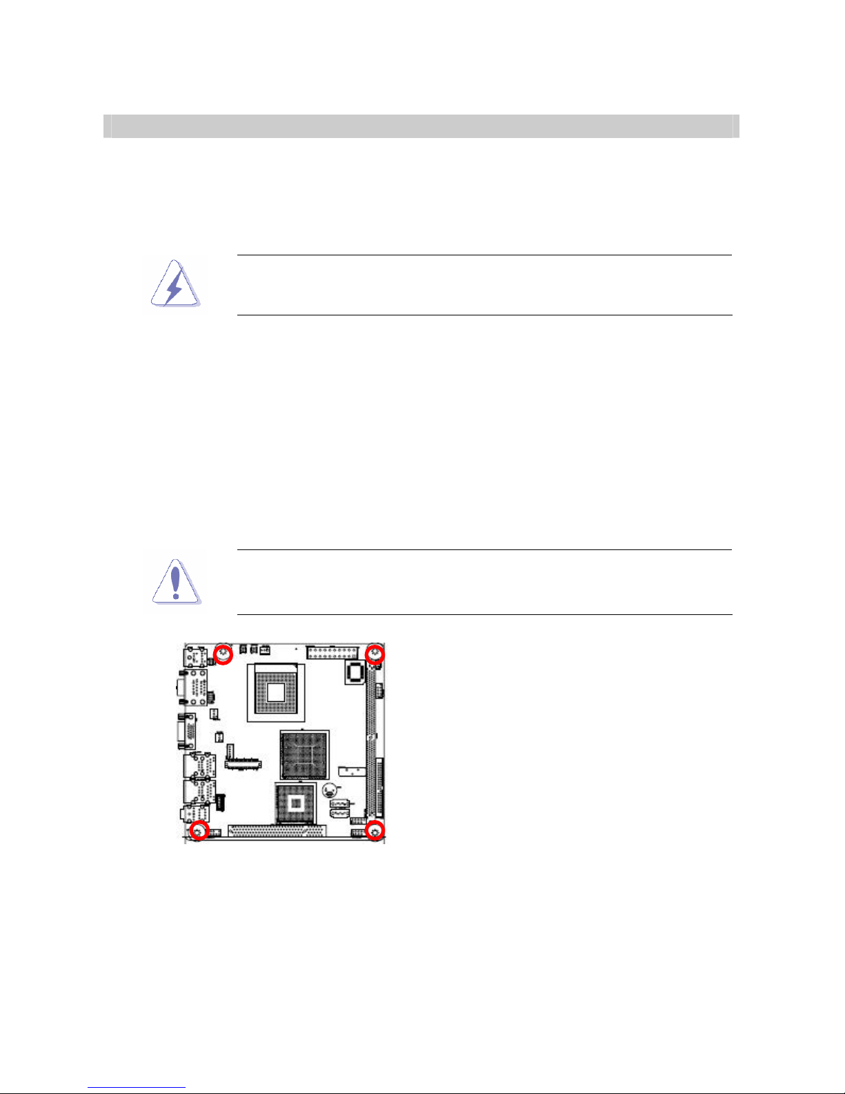
1.2.2 Screw Holes
Place four (4) screws into the holes indicated by circles to secure the motherboard to the
chassis.
Do not over tighten the screws! Doing so can damage the
motherboard.
Place this side towards the rear of the
chassis
i915GV2-LEI
14
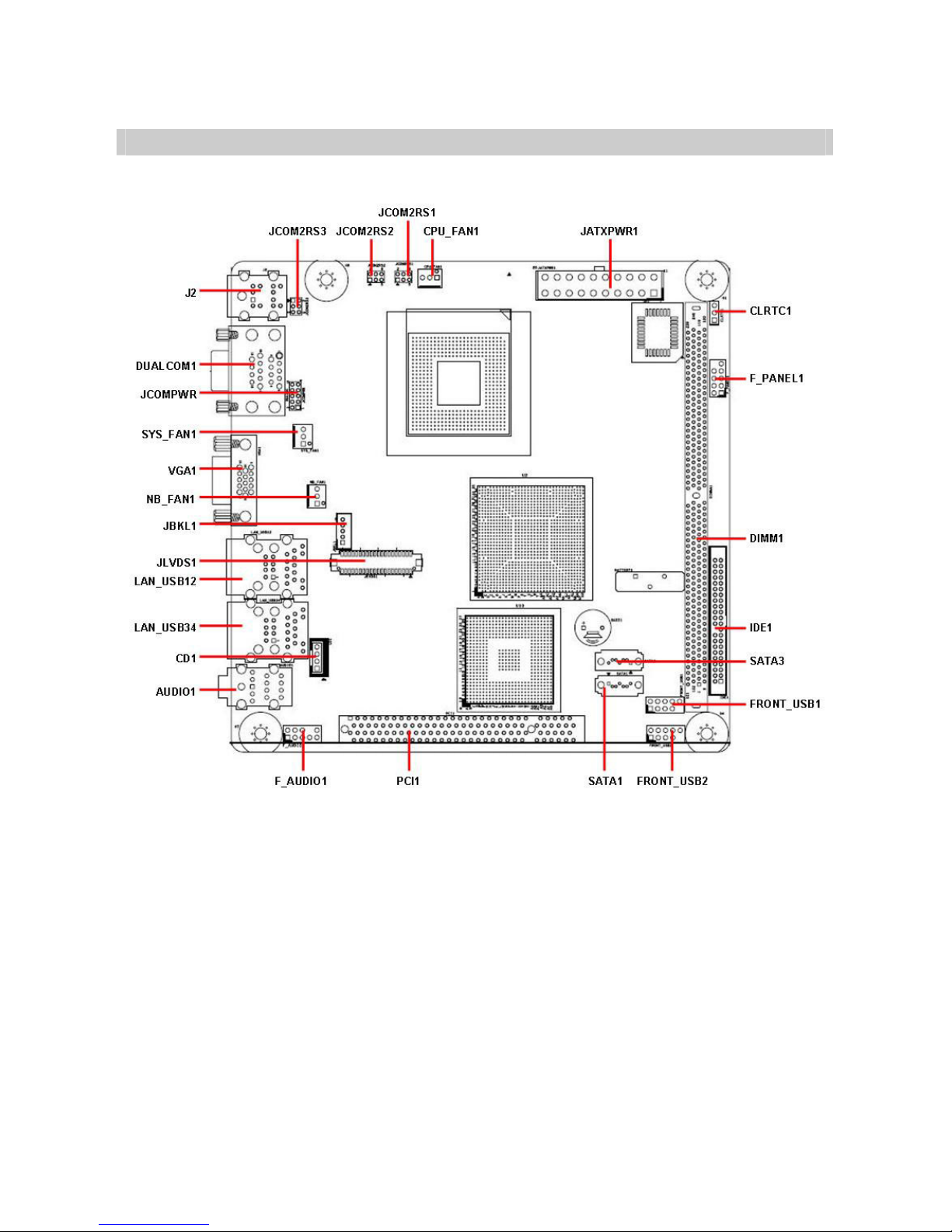
1.3 Motherboard Layout

User’s Manual
i915GV2-LEI
15
1.3.1 Layout Content List
Slots
Label Function Note Page
DIMM1 240-pin DDR2 DIMM slot N/A
PCI1 PCI slot N/A
Jumpers
Label Function Note Page
CLRTC1 Clear RTC RAM 3 x 1 header, pitch 2.00mm 27
JCOMPWR COM port RI/+5V/+12V
selection
5 x 2 header, pitch 2.00mm 28
JCOM2RS1,2,3 COM2 RS-232/422/485 Select 3 x 2 header, pitch 2.00mm 28,29
Rear Panel Connector
Label Function Note Page
J2 PS/2 keyboard and mouse 6-pin Mini-Din 30
DUALCOM1 Serial port connector x 2 D-sub 9-pin, male 30
VGA1 VGA port D-sub 15-pin, female 30
LAN_USB12 RJ-45 Ethernet connector x 1
USB connector x 2
30,31
LAN_USB34 RJ-45 Ethernet connector x 1
USB connector x 2
30,31
AUDIO1 Line-in port, Line-out port,
Microphone port,
8-Channel Audio I/O (3 jacks) 31

i915GV2-LEI
16
Internal Connector
Label Function Note Page
CD1 Optical drive audio connector 4 x 1 header, pitch 2.54mm 32
CPU_FAN1 CPU fan connector 4 x 1 wafer, pitch 2.54mm 32
NB_FAN1 (Reserved) 3 x 1 wafer, pitch 2.54mm N/A
SYS_FAN1 System fan connector 3 x 1 wafer, pitch 2.54mm 33
F_AUDIO1 Front headphone connector 10 x 1 header, pitch 2.54mm 33
F_PANEL1 System panel connector 5 x 2 header, pitch 2.54mm 34
FRONT_USB1 USB 2.0 connector 5 x 2 header, pitch 2.54mm 35
FRONT_USB2 USB 2.0 connector 5 x 2 header, pitch 2.54mm 35
IDE1 Primary IDE connector 22 x 2 header, pitch 2.00mm 36
JATXPWR1 ATX power connector 10 x 2 header 36
JBKL1 LCD Inverter connector 5 x 1 header, pitch 2.00mm 37
JLVDS1 LVDS connector HIROSE DF13S-40DP-1.25V 37
SATA1 Serial ATA connectors [black] 7-pin header 38
SATA3 Serial ATA connectors [blue] 7-pin header 38
User’s Manual
i915GV2-LEI
17
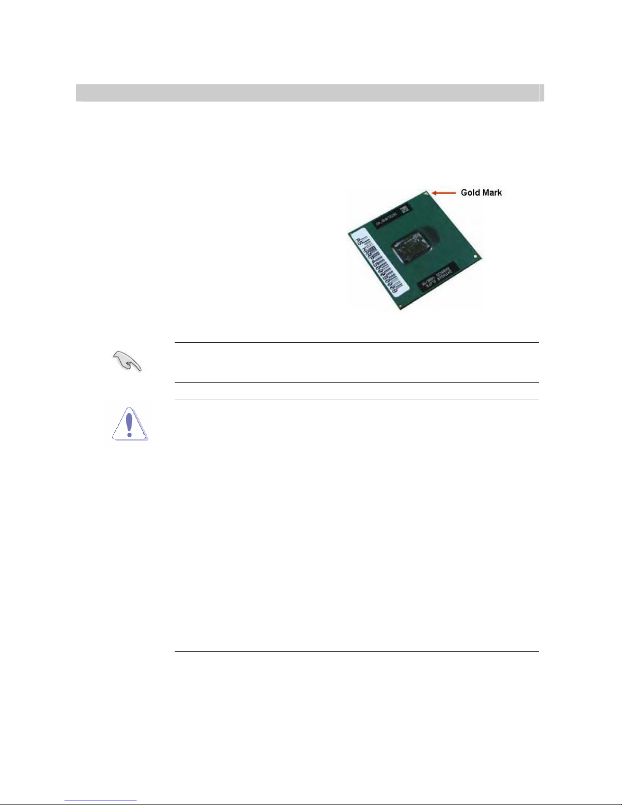
1.4 Central Processing Unit (CPU)
The motherboard comes with a surface mount 479-pin Zero Insertion Force (ZIF) socket
designed for the Intel® Pentium® M / Celeron M processor (Supports mPGA479M,
Micro-FCPGA).
Take one of the marked corner (with gold
triangle) on the CPU. This mark should
match a specific corner on the socket to
ensure correct installation.
zMake sure the AC power is off before you install the CPU.
zIf installing a dual-core CPU, connect the CPU fan cable to the
CPU_FAN1 connector to ensure system stability.
zYour boxed Intel® Pentium® M / Celeron M processor (supports
mPGA479M, Micro-FCPGA) package should come with
installation instructions for the CPU, heatsink, and the retention
mechanism. If the instructions in this section do not match the
CPU documentation, follow the latter.
zUpon purchase of the motherboard, make sure that the PnP cap
is on the socket and the socket contacts are not bent. Contact
your retailer immediately if the PnP cap is missing, or if you see
any damage to the PnP cap/socket contacts/motherboard
components. Your place of purchase or local distributor will
shoulder the cost of repair only if the damage is
shipment/transit-related.
zKeep the cap after installing the motherboard. Your place of
purchase or local distributor will process Return Merchandise
Authorization (RMA) requests only if the motherboard comes with
the cap on the socket.
zThe product warranty does not cover damage to the socket
contacts resulting from incorrect CPU installation/removal, or
misplacement/loss/ incorrect removal of the PnP cap.
i915GV2-LEI
18
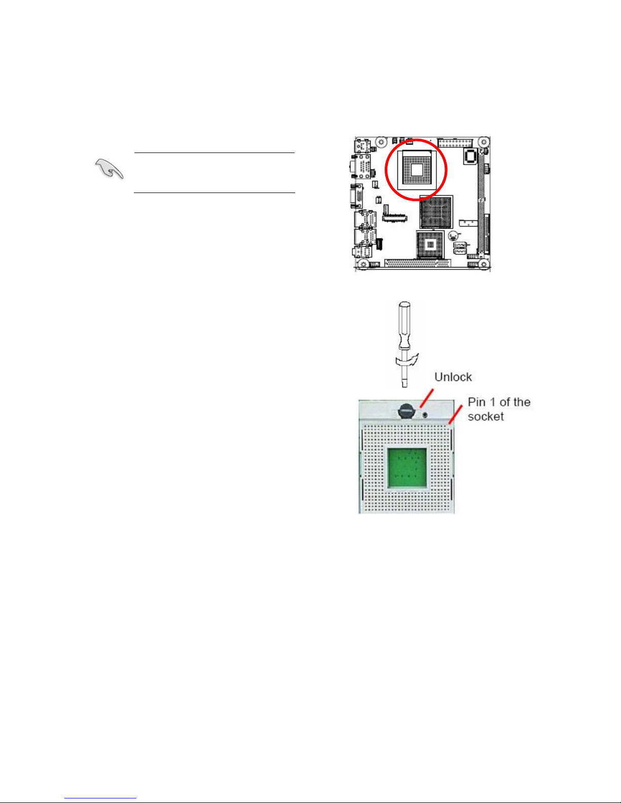
1.4.1 Installing the CPU
1. Locate the CPU socket on the motherboard.
Before installing the CPU,
make sure that the socket
box is facing towards you.
2. The processor socket comes with a
screw to secure the processor, please
unlock the screw first.

User’s Manual
i915GV2-LEI
19
3. Position the CPU above the socket and
the gold triangular mark on the CPU
must align with pin 1 of the CPU socket.
4. Carefully insert the CPU into the socket
until it fits in place ‘Gold mark’.
5. Turn the screw to the lock position.
The CPU fits in only one
correct orientation. DO NOT
force the CPU into the socket
to prevent bending the
connectors on the socket and
damaging the CPU.
After installation, make sure to plug-in the ATX power cable to the
motherboard.
This motherboard support Celeron M3 series or Pentium M7 series
CP
i915GV2-LEI
20
1.4.2 Installing the CPU Heatsink and Fan
The Intel® Pentium® M / Celeron M processor (supports mPGA479M, Micro-FCPGA)
requires a specially designed heatsink and fan assembly to ensure optimum thermal
condition and performance.
zInstall the motherboard to the chassis before you install the CPU
fan and heatsink assembly.
zWhen you buy a boxed Intel® processor, the package includes
the CPU fan and heatsink assembly. If you buy a CPU
separately, make sure that you use only Intel®‑certified
multi‑directional heatsink and fan.
If you purchased a separate CPU heatsink and fan assembly, make
sure that you have properly applied Thermal Interface Material to the
CPU heatsink or CPU before you install the heatsink and fan
assembly.
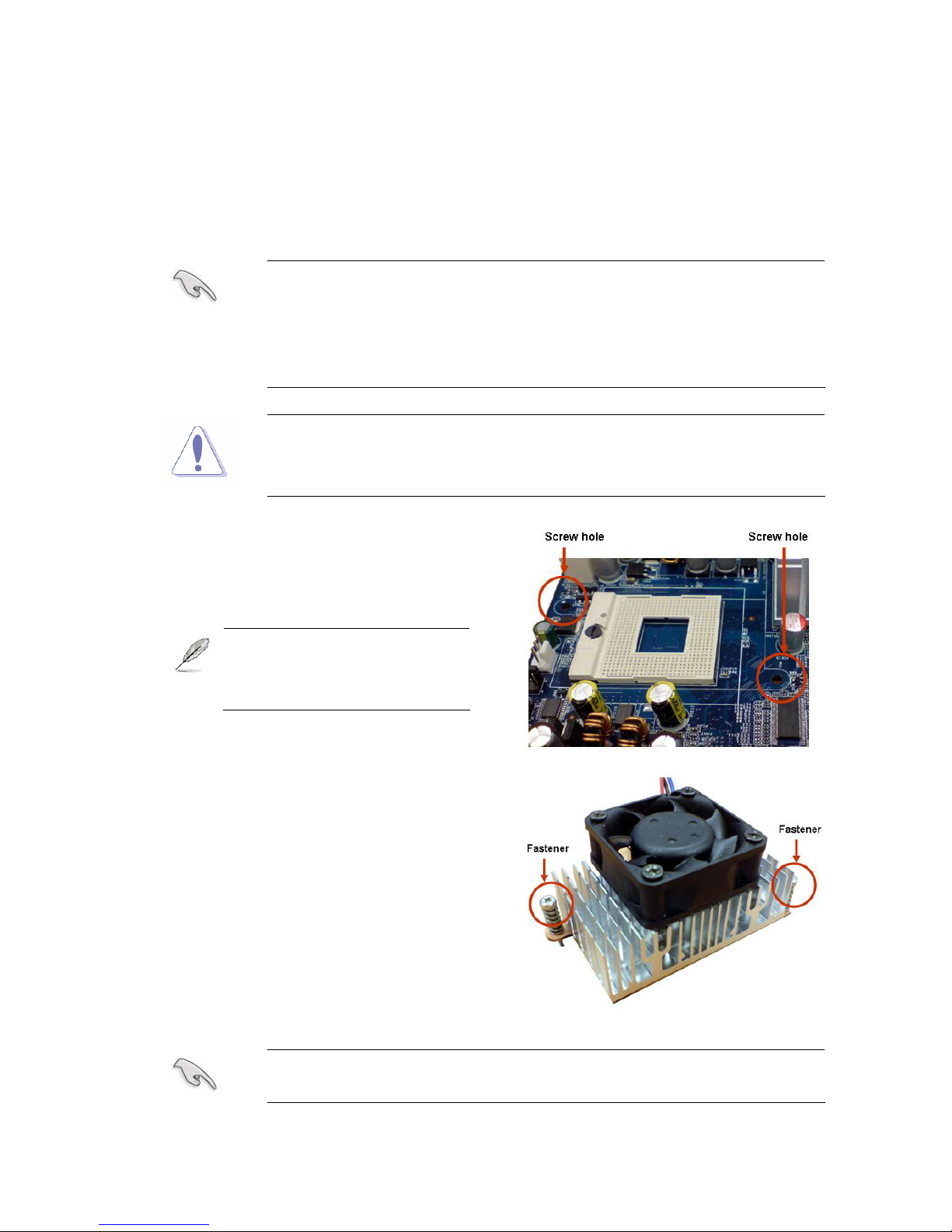
1. Place the heatsink on top of the installed
CPU, making sure that the two fasteners
match the holes on the motherboard.
Orient the heatsink and fan
assembly such that the CPU
fan cable is closest to the
CPU fan connector.
Make sure each fastener is oriented as shown, with the narrow groove
directed outward.
Table of contents
Other Advansus Motherboard manuals

Advansus
Advansus iQ96503-IQGM Installation and operation manual

Advansus
Advansus DS3630-945GSE User manual

Advansus
Advansus i965GM-DCQI User manual

Advansus
Advansus TC2220-CX700M User manual

Advansus
Advansus iQ965-IGM User manual

Advansus
Advansus i945GM3-DCQI User manual

Advansus
Advansus I865G-IM Series User manual

Advansus
Advansus iQ96503 User manual

Advansus
Advansus VCN700-LIC10 User manual

Advansus
Advansus MX965Q2 User manual


