Advansus VCN700-LIC10 User manual

VCN700-LIC10/15
VIA CN700 Mini-ITX Motherboard
User’s Manual
Ver. 1.00

VCN700-LIC10/15
2
Contents
Safety Information ..........................................................................................................4
Tec nical Support ............................................................................................................5
Conventions Used in T is Guide ....................................................................................5
Packing List .......................................................................................................................5
Revision History ...............................................................................................................6
Specifications Summary..................................................................................................7
Specifications Summary..................................................................................................8
Block Diagram...................................................................................................................9
Production Introduction ...............................................................................................11
1.1 Before you Proceed ................................................................................................11
1.2 Motherboard Overview............................................................................................11
1.2.1 Placement Direction ....................................................................................................................... 11
1.3 Motherboard Layout ................................................................................................12
1.4 System Memory ......................................................................................................13
1.4.1 DIMM Sockets Location ................................................................................................................. 13
1.4.2 Installing a DDR2 DIMM................................................................................................................. 14
1.4.3 Removing a DDR2 DIMM............................................................................................................... 14
1.5 Expansion Slots ......................................................................................................15
1.5.1 Installing an Expansion Card ......................................................................................................... 15
1.5.2 Configuring an Expansion Card ..................................................................................................... 15
1.5.3 PCI Slot .......................................................................................................................................... 15
1.6 Jumpers ..................................................................................................................16
1.6.1 Clear CMOS (CLRTC).................................................................................................................... 16
1.6.2 COM1 RI/+5V/+12V Selection (JCOMPWR1, JCOMPWR2)......................................................... 17
1.7 Connectors..............................................................................................................18
1.7.1 Rear Panel Connectors .................................................................................................................. 18
1.7.2 ATX Power Connector (ATX12V)................................................................................................... 20
1.7.3 Serial Port 2 Connector (COMB).................................................................................................... 21
1.7.4 CPU Fan Connector (CPU_FAN)................................................................................................... 21
1.7.5 Digital I/O Connector (DIO) ............................................................................................................ 22
1.7.6 Front Panel Audio Connector (F_AUDIO)...................................................................................... 22
1.7.7 System Panel Connector (F_PANEL1) .......................................................................................... 23
1.7.8 USB 2.0 Connector (F_USB1) ....................................................................................................... 24
1.7.9 Primary/Secondary IDE Connector (IDE1, IDE2)........................................................................... 25

User’s Manual
VCN700-LIC10/15
3
Contents
1.7.10 Amplifier Connector (JAMP1) .................................................................................................... 25
1.7.11 LCD Inverter Connector (JBKL1) ............................................................................................... 26
1.7.12 LVDS Connector (JLVDS1) ....................................................................................................... 27
1.7.13 SPI Pin Header Connector (JSPI) ............................................................................................. 27
1.7.14 Serial ATA Connector (SATA1, SATA2).................................................................................... 28
1.7.15 CPU Fan Connector (SYS_FAN)............................................................................................... 29
BIOS Setup ......................................................................................................................31
2.1 BIOS Setup Program ..............................................................................................31
2.1.1 Legend Box .................................................................................................................................... 32
2.1.2 List Box........................................................................................................................................... 32
2.1.3 Sub-menu....................................................................................................................................... 32
2.2 BIOS Menu Screen .................................................................................................33
2.2.1 Standard CMOS Features.............................................................................................................. 34
2.2.2 Advanced BIOS Features............................................................................................................... 36
2.2.3 Advanced Chipset Features ........................................................................................................... 42
2.2.4 Integrated Peripherals .................................................................................................................... 44
2.2.5 Power Management Setup............................................................................................................. 49
2.2.6 PC Health Status............................................................................................................................ 51
2.2.7 Load Setup Defaults....................................................................................................................... 52
2.2.8 Set Password ................................................................................................................................. 53
2.2.9 Save and Exit Setup....................................................................................................................... 54
2.2.10 Exit Without Saving.................................................................................................................... 55

VCN700-LIC10/15
4
Safety Information
Electrical safety
To prevent electrical shock hazard, disconnect the power cable from the electrical
outlet before relocating the system.
When adding or removing devices to or from the system, ensure that the power cables
for the devices are unplugged before the signal cables are connected. If possible,
disconnect all power cables from the existing system before you add a device.
Before connecting or removing signal cables from the motherboard, ensure that all
power cables are unplugged.
Seek professional assistance before using an adapter or extension cord. These
devices could interrupt the grounding circuit.
Make sure that your power supply is set to the correct voltage in your area. If you are
not sure about the voltage of the electrical outlet you are using, contact your local
power company.
If the power supply is broken, do not try to fix it by yourself. Contact a qualified service
technician or your retailer.
Operation safety
Before installing the motherboard and adding devices on it, carefully read all the
manuals that came with the package.
Before using the product, make sure all cables are correctly connected and the power
cables are not damaged. If you detect any damage, contact your dealer immediately.
To avoid short circuits, keep paper clips, screws, and staples away from connectors,
slots, sockets and circuitry.
Avoid dust, humidity, and temperature extremes. Do not place the product in any area
where it may become wet.
Place the product on a stable surface.
If you encounter technical problems with the product, contact a qualified service
technician or your retailer.
The symbol of the crossed out wheeled bin indicates that the product
(electrical and electronic equipment) should not be placed in
municipal waste. Check local regulations for disposal of electronic
products.

User’s Manual
VCN700-LIC10/15
5
Tec nical Support
If a problem arises with your system and no solution can be obtained from the user’s
manual, please contact your place of purchase or local distributor. Alternatively, please try
the following help resources for further guidance. Visit the Advansus website for FAQ,
technical guide, BIOS updates, driver updates, and other information:
http://www.advansus.com.tw/Support/Support.asp
Conventions Used in T is Guide
To make sure that you perform certain tasks properly, take note of the following symbols
used throughout this manual.
DANGER/WARNING: Information to prevent injury to yourself when
trying to complete a task.
CAUTION: Information to prevent damage to the components when
trying to complete a task.
IMPORTANT: Instructions that you MUST follow to complete a task.
NOTE: Tips and additional information to help you complete a task.
Packing List
Before you begin installing your single board, please make sure that the following materials
have been shipped:
1 x VIA CN700 Mini-ITX Main board
1 x CD-ROM contains the followings:
-User’s manual (this manual in PDF file)
-Drivers
1 x Startup Manual
If any of the above items is damaged or missing, please contact your
retailer.

VCN700-LIC10/15
6
Revision History
Revision Revision History Date
V 1.00 First release for PCB 1.00 December 03, 2008

User’s Manual
VCN700-LIC10/15
7
Specifications Summary
CPU On board VIA C7 1.0/1.5 GHz
Chipset VIA CN700
Memory One 240-pin DIMM up to total 1GB DDR2 400/533 SDRAM
Display 1 x VGA, 1 x LVDS 24 bit
Audio Realtek® ALC655, 5.1 Channel Audio
LAN Dual Realtek RTL 8110SC Gigabit LAN
Expansion
1 x PCI
I/O 2 x IDE, 2 x SATAII, 6 x USB 2.0, 2 x COM
Features
Others 4 bit DIO (4-in or 4-out), 6W Amp
System
CPU VIA C7 1.0/1.5 GHz onboard
FSB 400 MHz
BIOS Award 4 Mb Flash ROM BIOS
System Chipset VIA CN700/M
I/O Chipset ITE 8712F
Memory One 240-pin DIMM up to total 1GB DDR2 400/533 SDRAM
H/W Status Monitor Monitoring CPU temperature, voltage, and cooling fan status. Auto throttling
control when CPU overheats
Expansion Slots 1 x PCI (PCI Rev. 2.3 compliant)
DIO 4-bit (4-in or 4-out)
Wake up on LAN or
Ring Both (PME / RPL / WOR)
Display
Chipset Integrated VIA UniChrome Pro AGP graphics with MPEG-2 Decoding
Acceleration
Display Memory VIA S3 UniChrome Pro II 3D Graphic Engine Shared system memory up to
128MB I/O
Max. Resolution 1920 x 1440 @75Hz
Dual Display Yes(CRT+LVDS)
VGA Yes
LVDS Yes ,Dual-channel 24-bit LVDS
LVDS Backlight Power Yes

VCN700-LIC10/15
8
Specifications Summary
Audio
Audio Codec Realtek® ALC655, 5.1 Channel Audio
Audio Interface Mic in, Line in, Line out
Audio Amplifier (W) Dual 6W Amp.(TPA3005D2 )
Ethernet
LAN1 Realtek RTL 8110SC Gigabit LAN
Back I/O Port
Back Panel
1 x PS2 mouse port
1 x PS2 keyboard port
1 x VGA port
1 x LPT port
1 x RS-232 COM port
1 x LAN port
4 x USB 2.0 ports
3 x Audio jacks: line-out, line-in, mic-in
Internal I/O Connector
Internal I/O
1 x RS-232 COM connector
2 x SATA connectors
2 x IDE port connectors
1 x USB 2.0 header for 2 USB ports
1 x DIO connector (4 IN or 4 OUT)
1 x Amplifier connector
1 x Front panel header
1 x 20 pin ATX power connector
1 x Front panel audio connector
1 x CPU fan connector
1 x System fan connector
Mechanical & Environmental
Power Type ATX mode
Size (L x W) 170mm x 170mm
* Specifications are subject to change without notice.

User’s Manual
VCN700-LIC10/15
9
Block Diagram

VCN700-LIC10/15
10
This chapter describes the main board
features and the new technologies
it supports.
1
11
1
Product
introduction
1
11
1
Product
introduction

User’s Manual
VCN700-LIC10/15
11
Production Introduction
1.1 Before you Proceed
Take note of the following precautions before you install motherboard components or
change any motherboard settings.
Unplug the power cord from the wall socket before touching any
component.
Use a grounded wrist strap or touch a safely grounded object or a
metal object, such as the power supply case, before handling
components to avoid damaging them due to static electricity
Hold components by the edges to avoid touching the ICs on
them.
Whenever you uninstall any component, place it on a grounded
antistatic pad or in the bag that came with the component.
Before you install or remove any component, ensure that the ATX
power supply is switched off or the power cord is detached from
the power supply. Failure to do so may cause severe damage to
the motherboard, peripherals, and/or components.
1.2 Motherboard Overview
Before you install the motherboard, study the configuration of your chassis to ensure that
the motherboard fits into it. Refer to the chassis documentation before installing the
motherboard.
Make sure to unplug the power cord before installing or removing the
motherboard. Failure to do so can cause you physical injury and
damage motherboard components.
1.2.1 Placement Direction
When installing the motherboard, make sure that you place it into the chassis in the correct
orientation. The edge with external ports goes to the rear part of the chassis as indicated in
the image below.

VCN700-LIC10/15
12
1.3 Motherboard Layout

User’s Manual
VCN700-LIC10/15
13
1.4 System Memory
1.4.1 DIMM Sockets Location
The motherboard comes with four 240-pin Double Data Rate 2 (DDR2) Dual Inline Memory
Modules (DIMM) sockets.
A DDR2 module has the same physical dimensions as a DDR DIMM but has a 240-pin
footprint compared to the 184-pin DDR DIMM. DDR2 DIMMs are notched differently to
prevent installation on a DDR DIMM socket. The following figure illustrates the location of
the sockets:

VCN700-LIC10/15
14
1.4.2 Installing a DDR2 DIMM
Make sure to unplug the power supply before adding or removing
DIMMs or other system components. Failure to do so may cause
severe damage to both the motherboard and the components.
1. Unlock a DIMM socket by pressing the
retaining clips outward
2. Align a DIMM on the socket such that the
notch on the DIMM matches the break on
the socket.
3. Firmly insert the DIMM into the socket until
the retaining clips snap back in place and
the DIMM.
A DDR2 DIMM is keyed with a notch so that it fits in only one
direction. DO NOT force a DIMM into a socket to avoid damaging
the DIMM.
The DDR2 DIMM sockets do not support DDR DIMMs. DO NOT
install DDR DIMMs to the DDR2 DIMM socket.
1.4.3 Removing a DDR2 DIMM
1. Simultaneously press the retaining clips
outward to unlock the DIMM.
2. Remove the DIMM from the socket.
Support the DIMM lightly with your fingers when pressing the retaining
clips. The DIMM might get damaged when it flips out with extra force.
User’s Manual
VCN700-LIC10/15
15
1.5 Expansion Slots
In the future, you may need to install expansion cards. The following sub‑sections describe
the slots and the expansion cards that they support.
Make sure to unplug the power cord before adding or removing
expansion cards. Failure to do so may cause you physical injury and
damage motherboard components.
1.5.1 Installing an Expansion Card
1. Before installing the expansion card, read the documentation that came with it and
make the necessary hardware settings for the card.
2. Remove the system unit cover (if your motherboard is already installed in a chassis).
3. Remove the bracket opposite the slot that you intend to use. Keep the screw for later
use.
4. Align the card connector with the slot and press firmly until the card is completely
seated on the slot.
5. Secure the card to the chassis with the screw you removed earlier.
6. Replace the system cover.
1.5.2 Configuring an Expansion Card
After installing the expansion card, configure it by adjusting the software settings.
1. Turn on the system and change the necessary BIOS settings if any.
2. Assign an IRQ to the card if needed. Refer to the tables on the next page.
3. Install the software drivers for the expansion card.
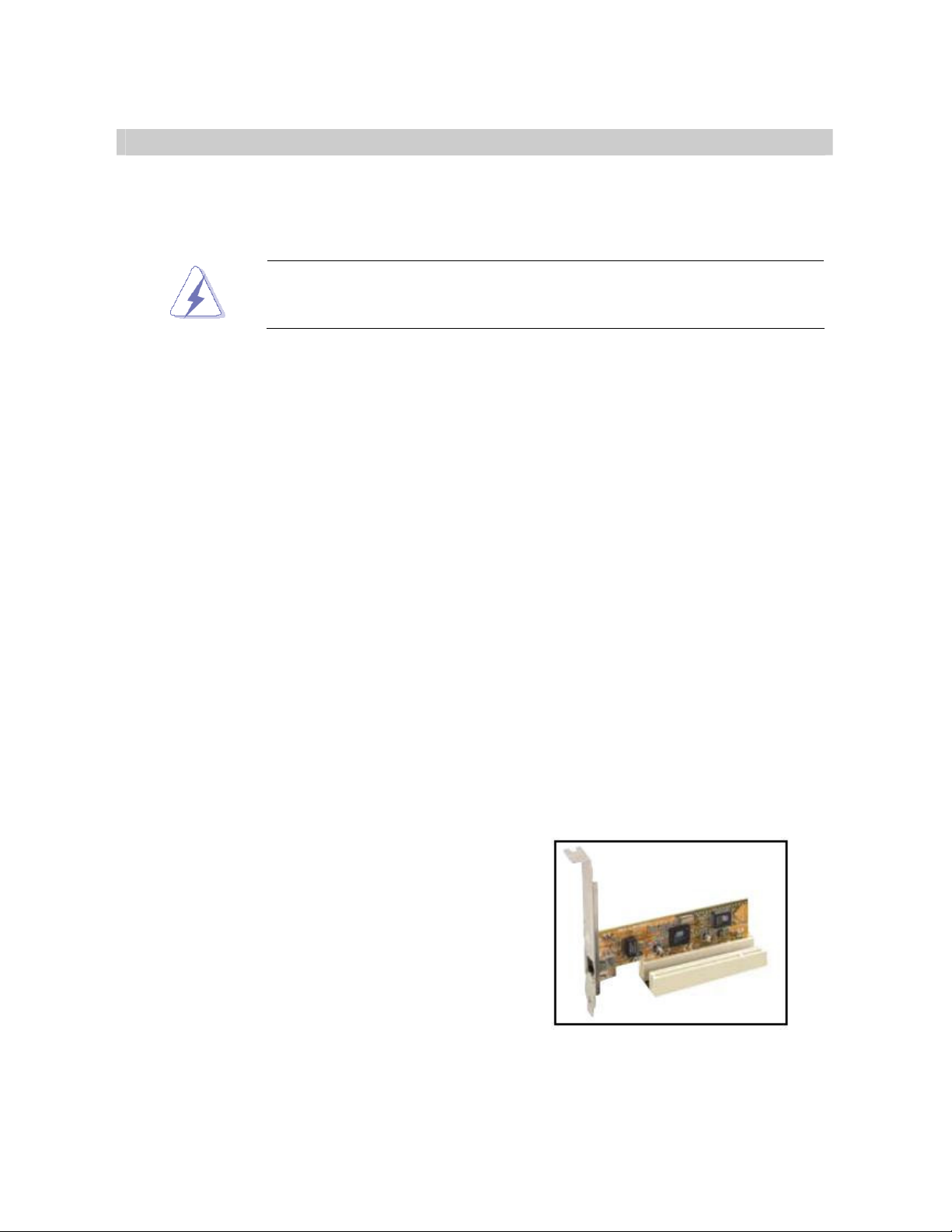
1.5.3 PCI Slot
This motherboard has two PCI slots. The PCI
slots support cards such as a LAN card, SCSI
card, USB card, and other cards that comply
with PCI specifications. The figure shows a LAN
card installed on a PCI slot.

VCN700-LIC10/15
16
1.6 Jumpers
1.6.1 Clear CMOS (CLRTC)
This jumper allows you to clear the Real Time Clock (RTC) RAM in CMOS. You can clear
the CMOS memory of date, time, and system setup parameters by erasing the CMOS RTC
RAM data. The onboard button cell battery powers the RAM data in CMOS, which include
system setup information such as system passwords. To erase the RTC RAM:
1. Turn OFF the computer and unplug the power cord.
2. Remove the onboard battery.
3. Move the jumper cap from pins 1-2 (default) to pins 2-3. Keep the cap on pins 2-3 for
about 5~10 seconds, then move the cap back to pins 1-2.
4. Re-install the battery.
5. Plug the power cord and turn ON the computer.
6. Hold down the <Del> key during the boot process and enter BIOS setup to re-enter
data.
Except when clearing the CMOS, never remove the cap on CLRTC
jumper default position. Removing the cap will cause system boot
failure!
Normal (Default)
Clear RTC

User’s Manual
VCN700-LIC10/15
17
1.6.2 COM1 RI/+5V/+12V Selection (JCOMPWR1, JCOMPWR2)
JCOMPWR1
JCOMPWR2
+5V
+12V
Ring *
JCOMPWR2 JCOMPWR1

VCN700-LIC10/15
18
1.7 Connectors
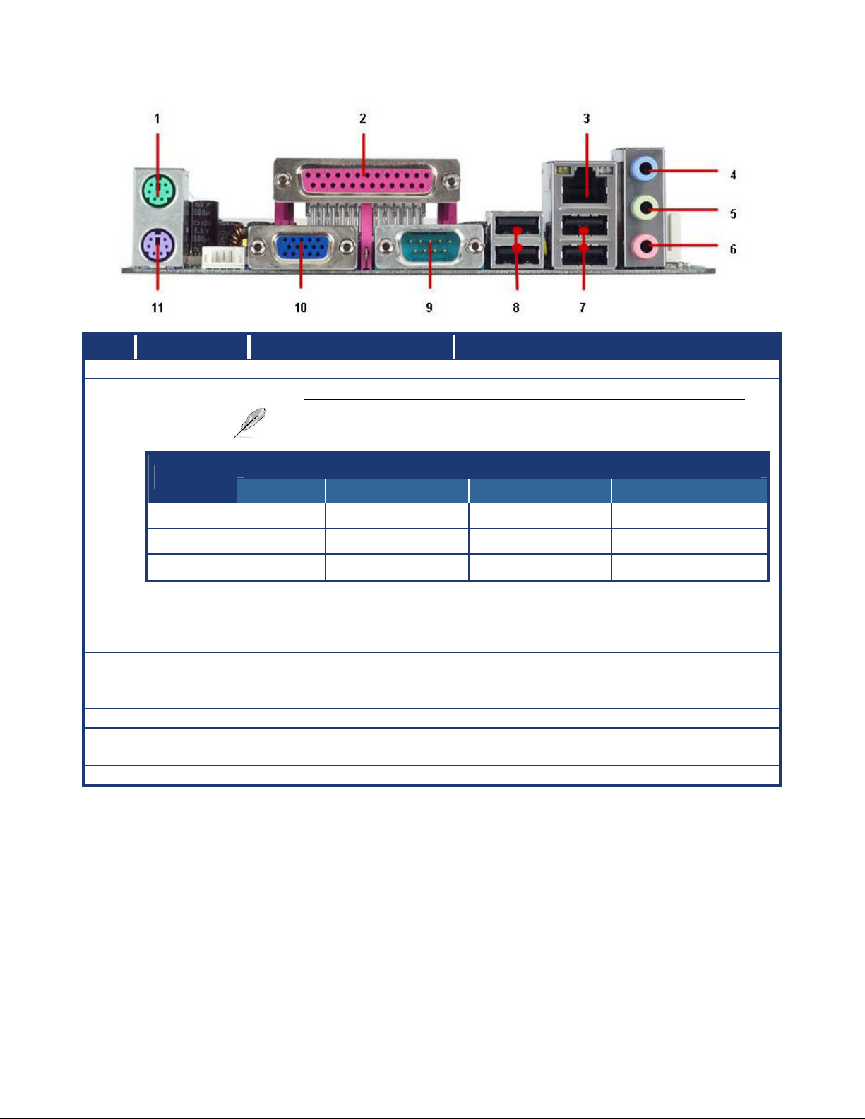
1.7.1 Rear Panel Connectors
No Label Function Description
1 KB_MS PS/2 mouse connector The standard PS/2 mouse DIN connector is
for a PS/2 mouse.
2 LPT Parallel port connector
This 25-pin parallel port is a standard
printer port that supports Enhanced Parallel
Port (EPP) and Extended Capabilities
Parallel Port (ECP) mode
LAN (RJ-45) connector
This port allows Gigabit connection to a
Local Area Network (LAN) through a
network hub. Refer to the table below for
the LAN port LED indications. The optional
10/100 Mbps LAN controller allows 10/100
Mbps connection to a Local Area Network
(LAN) through a network hub.
3 LAN_USB67
ACT / LINK LED SPEED LED
Status Description
Status Description
OFF No link OFF 10Mbps connection
Orange Linked ORANGE 100Mbps connection
Blinking
Data activity
GREEN 1Gbps connection
4 AUDIO1 Line-In port (Light Blue). This port connects a tape, CD, DVD player,
or other audio sources.
5 AUDIO1 Line-Out port (Lime) This port connects a headphone or a
speaker. In 4-channel, 6-channel, and
8-channel configuration, the function of this
port becomes Front Speaker Out.
User’s Manual
VCN700-LIC10/15
19
No Label Function Description
6 AUDIO1 Microphone port (Pink) This port connects a microphone.
Headset
Port 2-channel
4-channel 6-channel 8-channel
Light Blue
Line in Line in Line in Line in
Lime Line out Front speaker out
Front speaker out
Front speaker out
Pink Mic In Mic In Mic In Mic In
7 LAN_USB67 USB 2.0 connector These two 4-pin Universal Serial Bus (USB)
ports are available for connecting USB 2.0
devices.
8 R_USB USB 2.0 connector These two 4-pin Universal Serial Bus (USB)
ports are available for connecting USB 2.0
devices.
9 COMA Serial port connector D-Sub 9-pin, male
10 VGA VGA port This 15-pin port is for a VGA monitor or
other VGA-compatible devices.
11 KB_MS PS/2 KB connector This port is for a PS/2 keyboard
Refer to the audio configuration table below for the function
of the audio ports in
2, 4, 6, or 8
-
channel configuration.
VCN700-LIC10/15
20
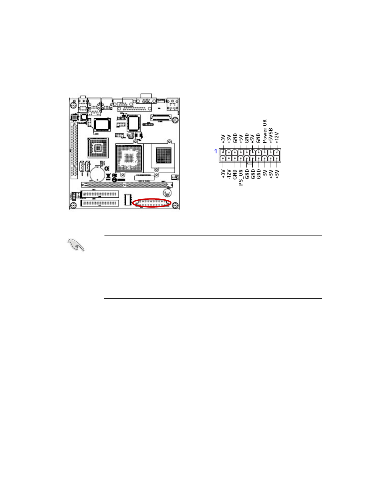
1.7.2 ATX Power Connector (ATX12V)
This connector is for an ATX power supply plugs. The power supply plugs are designed to
fit these connectors in only one orientation. Find the proper orientation and push down
firmly until the connectors completely fit.
Important notes on the Motherboard Power Requirements
Make sure that your ATX 12V power supply can provide 8A on
the +12V lead and at least 1A on the +5-volt standby lead
(+5VSB). The minimum recommended wattage is 230W, or
300W for a fully configured system. The system can become
unstable and might experience difficulty powering up if the power
supply is inadequate.
You must install a PSU with a higher power rating if you intend to
install additional devices.
This manual suits for next models
1
Table of contents
Other Advansus Motherboard manuals

Advansus
Advansus TC2220-CX700M User manual

Advansus
Advansus I865G-IM Series User manual

Advansus
Advansus MX965Q2 User manual

Advansus
Advansus i945GM3-DCQI User manual

Advansus
Advansus i915GV2-LEI User manual

Advansus
Advansus LM5560-Q45 User manual

Advansus
Advansus iQ96503-IQGM Installation and operation manual

Advansus
Advansus iQ96503 User manual

Advansus
Advansus i965GM-DCQI User manual

Advansus
Advansus iQ965-IGM User manual


