Advantage Controls RA-6 User manual

1
Manual
RA-6
Six-Channel
Remote Alarm
Installation
Maintenance
Repair
Manual
Advantage Controls
4700 Harold-Abitz Dr.
Muskogee, OK 74403
Phone: 800-743-7431
Fax: 888-686-6212
www.advantagecontrols.com

2
RA-6 Unit Manual
Table of Contents
Contents Page
I. Introduction ................................................................................3
II. Installation..................................................................................3
Wiring Diagrams ........................................................................4
III. System Operation ......................................................................5
IV. Warranty and Factory Service Policies ......................................6

3
I. Introduction
The Advantage Controls RA-6 Remote Alarm unit is designed to communicate an alarm or abnormal
condition of operating equipment to areas outside the equipment area. The unit is comprised of a
base unit and a remote unit. The RA-6 has 6 input channels and each channel can be individually
congured in the base unit to monitor dierent types of input signals, such as dry contact, AC/
DC voltage or open collector transistor. These signals can be from virtually any source such as
conductivity/resistivity monitors, level switches, pressure switches, limit switches, motor contactors,
etc.
The base unit provides power for the remote unit and has jumpers for conguring the input channels.
Channels 1-4 have a xed 1-second delay and channels 5-6 have either a xed 1-second delay or
an adjustable time delay. The remote unit has a green power on LED, a red alarm LED and red
individual alarm LED’s. An audible alarm is provided with an alarm silence switch. The alarm silence
can be maintained or timed. A power failure alarm is incorporated into the remote unit and also an
optional alarm relay output..
II. Installation
The base unit is normally mounted in close proximity to the equipment to be monitored. The base unit
requires 120 VAC power, 2 conductors for each channel input used and a single multiconductor cable for
connection to the remote unit.
Wire the 120 VAC power to the power in terminals. Connect the 2 signal wires from each source to be
monitored to the desired input channel. Any channels not used can be left open. Refer to the supplied
drawings for each unit for wiring information.
The base unit jumpers must be programmed for the type of signal to be applied to each channel.
WARNING: The unit can be damaged if the wrong signal type is applied to a channel. The channels are set
as 28-120 V(AC or DC) by default. Refer to the jumper settings drawing for jumper settings for each channel.
If an adjustable delay is desired for channels 5 or 6, the corresponding jumper must be moved to enable the
adjustable delay.
The remote unit can be mounted in any convenient location where it can be seen and heard by operating
personnel. The multiconductor cable to wire the base to the remote unit must have 2 wires for ground and
12V power and 1 wire for each channel used. For example, if 4 channels are used, a 6-conductor cable can
be used. To wire the remote unit, remove the 4 screws holding the cover in place, pull the cable through
the cord grip connector in the bottom of the box and connect the wires to the terminal strip as shown in the
drawing. If required, set the jumpers for the power fail or alarm recycle features.
NOTE: If the RA6R remote unit is used with a base unit that has the recycle circuitry installed, the recycle
jumper on the base unit must be placed in the o position. Base units that do not have the recycle circuitry
installed must only be used with the RA6R remote board for the recycle function to operate properly.
!

4
Note: Any and all channels may be wired in any of the congurations shown.
Wiring Diagram
+12V and GND must be connected
JUMPER SETTINGS
W/ SIGNAL LEVELS
Note: All 6 alarm channels are identical.
Only channel 1 jumper settings
are show in detail, but the settings
apply to all channels.
J108 & J1116 determine if CH5 and/or CH8 will delay the transmission of the respective alarm
signals to the remote. If either delay is selected, it’s timing (delay) is adjustable as follows:
CH5 -- 15-30 sec.
CH6 -- 1.5-3 min.
Recycle
timing
(delay)
adjustment
If “ON”, all alarms are
recycled at a rate determined
by the “RECYCLE” timing
adjustment.
CAUTION!
DO NOT APPLY VOLTAGE
TO AN INPUT WHEN IT IS
CONFIGURED AS A DRY
CONTACT INPUT.
SIGNAL INPUTS POWER
IN
OUTPUTS TO
REMOTE UNIT
NOTE: Reset
silences the
audible alarm
in the remote
unit.
DRY CONTACT
INPUT
(SWITCH OR RELAY)
12-24 VOLT
INPUT
(AC or DC)
12-120 VOLT
INPUT
(AC or DC)
TRANSISTOR
CLOSURE
(NPN OPEN COL.)
Jumper Settings (w/ signal levels)
DC VOLTAGE SIGNAL
(not polarity sensitive)
DRY CONTACT
(RELAY or SWITCH)
BASE UNIT OUTPUT
TERMINAL STRIP
REMOTE UNIT TERMINAL STRIP
BASE UNIT INPUT
TERMINAL STRIP
BASE TO REMOTE UNIT CABLE
NOTE: Signals are
12 VDC or less.
RESET - SILENCES
AUDIBLE ALARM
May be omitted
if not used.
AC SIGNAL
POWER IN
NOT NORMALLY USED
CH5 CH6
Wire these
in any of the
congurations
shown for CH1-CH4.
H
N
G
TRANSISTOR
CLOSURE
(ONE POSSIBLE
CONFIGURATION)

5
CAUTION
1. There are live circuits inside the controller even when the power switch on the front panel is in
the OFF position. Never open the front panel without rst disconnecting power from the outlet.
Prewired controllers are supplied with an 8 foot, 18 AWG power cord with USA style plug. A #1
Phillips driver is required to open the front panel.
2. Low voltage signal wires (probes, ow switch, water meter, etc.) should never be run
in conduit with high voltage (like 115VAC) wires.
3. Never attempt to land connections to the controller without rst disconnecting power from the outlet.
4. Do not block access to disconnect power during mounting and installation.
5. The controller should be connected to its own isolated circuit breaker, and for best
results, the ground should be a true earth ground, not shared. Any attempt to bypass the grounding
will compromise the safety of users and property.
6. The electrical installation of the controller must be performed by trained personnel only and
conform to all applicable National, State and Local codes.
7. Operation of this product in a manner not specied by the manufacturer may result in damage
to equipment or persons.
8. Avoid mounting in locations that expose the controller to direct sunlight, vapors, vibration,
liquid spills or extreme temperatures; less than 0°F (-17.8°C) or greater than 120°F (50°C).
EMI(electromagnetic interference) from radio transmissions and electric motors can also cause
damage or interference and should be avoided.
! !
III. System Operation
When power is applied to the base unit, the green power LED will light. If no alarms are active, all other LED’s
will be o and the audible alarm is silent.
When a signal is applied to an input channel on the base unit, after the delay time, a signal is sent to the
remote unit. At the remote unit, the alarm LED for the channel lights, the alarm LED lights and the audible
alarm sounds. If the optional alarm relay is installed, the relay will energize. If the signal to the base unit
clears, the alarm indicators at the remote unit will clear automatically.
When the audible alarm is active, pressing the alarm silence switch will silence the audible alarm. If the alarm
clears and then returns, the audible alarm will sound. If an alarm is active and the audible alarm has been
silenced, a new alarm becoming active on another channel will cause the audible alarm to sound.
By default, when the alarm silence switch is pressed, the audible alarm will remain silenced. By reconguring
jumpers J8, J9 and J10 on the remote unit, the audible alarm can be programmed to recycle after a delay
when the audible alarm has been silenced.
The remote unit has an optional power fail alarm. By default, this option is disabled. By moving jumper J1 on
the remote unit to the E position, the power fail alarm is enabled. If power is lost to the remote unit with this
feature enabled, the audible alarm will beep once every 10 seconds. No alarm LED’s will be on. The power
fail alarm will operate for approximately 1-½ hours. If power is not restored within this time, the alarm will stop.

6
IV. Manufacturer’s Product Warranty
Advantage Controls warrants to the original purchaser that the products it manufactures will be free from
defects in material and workmanship for a period of twelve months from the date of shipment on parts and
ninety days on labor. Some non-Advantage manufactured resale items may have warranty periods less
than twelve months. Advantage Controls’ obligation under this warranty is limited exclusively to the repair or
replacement of any product that Advantage nds to be defective. Items returned for warranty consideration
must have a return authorization number and be properly packaged, shipped prepaid and insured. This war-
ranty is valid only when the products are properly installed, maintained and used for the purpose for which
they were designed. Misuse, neglect, damage, accident, improper repair, or modication not authorized in
writing by Advantage Controls will void this warranty.
There are no warranties, expressed or implied, including the implied warranties for merchantability or tness
for a particular purpose that extend beyond the limited warranty expressly stated above. Advantage Controls’
liability to any purchaser of its products, whether in contract or in tort, and whether arising out of warranties,
representations, instructions, installations, or defects from any cause, will be limited exclusively to repairing
or replacing the product or any part thereof under the conditions set out above.
30 Day Billing Memo Policy
Advantage Controls maintains a unique factory exchange program to ensure uninterrupted service with mini-
mum downtime. If your controller malfunctions, call 1 (918-686-6211 (international customers dial +1 918
686-6211), and provide our technician with Model and Serial Number information. If they are unable to di-
agnose and solve your problem over the phone, a fully warranted replacement unit will be shipped, usually
within 48 hours, on a 30 Day Billing Memo. This service requires a purchase order and the replacement unit
is billed to your regular account for payment. The replacement unit will be billed at current list price for that
model less any applicable resale discount. Upon return of your old unit, credit will be issued to your account
if the unit is in warranty. If the unit is out of warranty or the damage not covered, a partial credit will be applied
based upon a prorated replacement price schedule dependent on the age of the unit. Any exchange covers
only the controller or pump. Electrodes and other external accessories are not included.

7
Get the Advantage in Water Treatment Equipment
Advantage Controls can give you the Advantage in products, knowledge
and support on all of your water treatment equipment needs.
Cooling Tower Controllers
Boiler Blow Down Controllers
Blow Down Valve Packages
Solenoid Valves
Water Meters
Chemical Metering Pumps
Corrosion Coupon Racks
Chemical Solution Tanks
Solid Feed Systems
Feed Timers
Filter Equipment
Glycol Feed Systems
Pre Fabricated Systems
Get the Advantage
5
4
3
2
1
0
9
8
7
6
BACK
HOME
HELP
ENTER
CANCEL
SET UP
RUN
5
4
3
2
1
ENTER
HELP
5
4
3
CHANGE
RUN
SET UP
0
9
8
2
1
7
6
HOME
BACK

8
Table of contents
Popular Security System manuals by other brands
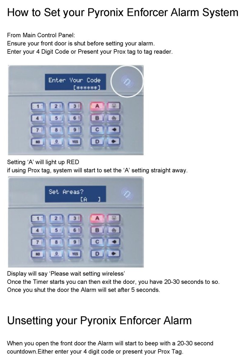
Pyronix
Pyronix Enforcer How to set
TSec SpA
TSec SpA MACS instruction manual

Safety Technology International
Safety Technology International STI-SA5000 SERIES manual
Swann
Swann SW231PC4 operating instructions
Alert-it Care Systems
Alert-it Care Systems P163 Series Handbook
Easywave
Easywave RTS26 STATUS Series quick start guide
