Advantech EKI-2701HPI-AE User manual

User Manual
EKI-2701HPI-AE
Industrial IEEE 802.3at Gigabit
PoE Injector

EKI-2701HPI-AE User Manual ii
Copyright
The documentation and the software included with this product are copyrighted 2012
by Advantech Co., Ltd. All rights are reserved. Advantech Co., Ltd. reserves the right
to make improvements in the products described in this manual at any time without
notice. No part of this manual may be reproduced, copied, translated or transmitted
in any form or by any means without the prior written permission of Advantech Co.,
Ltd. Information provided in this manual is intended to be accurate and reliable. How-
ever, Advantech Co., Ltd. assumes no responsibility for its use, nor for any infringe-
ments of the rights of third parties, which may result from its use.
Acknowledgements
Intel and Pentium are trademarks of Intel Corporation.
Microsoft Windows and MS-DOS are registered trademarks of Microsoft Corp.
All other product names or trademarks are properties of their respective owners.
Product Warranty (5 years)
Advantech warrants to you, the original purchaser, that each of its products will be
free from defects in materials and workmanship for five years from the date of pur-
chase.
This warranty does not apply to any products which have been repaired or altered by
persons other than repair personnel authorized by Advantech, or which have been
subject to misuse, abuse, accident or improper installation. Advantech assumes no
liability under the terms of this warranty as a consequence of such events.
Because of Advantech’s high quality-control standards and rigorous testing, most of
our customers never need to use our repair service. If an Advantech product is defec-
tive, it will be repaired or replaced at no charge during the warranty period. For out-
of-warranty repairs, you will be billed according to the cost of replacement materials,
service time and freight. Please consult your dealer for more details.
If you think you have a defective product, follow these steps:
1. Collect all the information about the problem encountered. (For example, CPU
speed, Advantech products used, other hardware and software used, etc.) Note
anything abnormal and list any onscreen messages you get when the problem
occurs.
2. Call your dealer and describe the problem. Please have your manual, product,
and any helpful information readily available.
3. If your product is diagnosed as defective, obtain an RMA (return merchandize
authorization) number from your dealer. This allows us to process your return
more quickly.
4. Carefully pack the defective product, a fully-completed Repair and Replacement
Order Card and a photocopy proof of purchase date (such as your sales receipt)
in a shippable container. A product returned without proof of the purchase date
is not eligible for warranty service.
5. Write the RMA number visibly on the outside of the package and ship it prepaid
to your dealer.
Edition 1
Printed in Taiwan November 2012

iii EKI-2701HPI-AE User Manual
Declaration of Conformity
CE
This product has passed the CE test for environmental specifications when shielded
cables are used for external wiring. We recommend the use of shielded cables. This
kind of cable is available from Advantech. Please contact your local supplier for
ordering information.
CE
This product has passed the CE test for environmental specifications. Test conditions
for passing included the equipment being operated within an industrial enclosure. In
order to protect the product from being damaged by ESD (Electrostatic Discharge)
and EMI leakage, we strongly recommend the use of CE-compliant industrial enclo-
sure products.
FCC Class A
Note: This equipment has been tested and found to comply with the limits for a Class
A digital device, pursuant to part 15 of the FCC Rules. These limits are designed to
provide reasonable protection against harmful interference when the equipment is
operated in a commercial environment. This equipment generates, uses, and can
radiate radio frequency energy and, if not installed and used in accordance with the
instruction manual, may cause harmful interference to radio communications. Opera-
tion of this equipment in a residential area is likely to cause harmful interference in
which case the user will be required to correct the interference at his own expense.

EKI-2701HPI-AE User Manual iv
Advantech Customer Services
Each and every Advantech product is built to the most exacting specifications to
ensure reliable performance in the unusual and demanding conditions typical of
industrial environments. Whether your new Advantech equipment is destined for the
laboratory or the factory floor, you can be assured that your product will provide the
reliability and ease of operation for which the name Advantech has come to be
known.
Your satisfaction is our number one concern. Here is a guide to Advantech's cus-
tomer services. To ensure you get the full benefit of our services, please follow the
instructions below carefully.
Technical Support and Assistance
1. Visit the Advantech web site at http://support.advantech.com where you can find
the latest information about the product.
2. Contact your distributor, sales representative, or Advantech's customer service
center for technical support if you need additional assistance. Please have the
following information ready before you call:
–Product name and serial number
–Description of your peripheral attachments
–Description of your software (operating system, version, application software,
etc.)
–A complete description of the problem
–The exact wording of any error messages

v EKI-2701HPI-AE User Manual
Contents
Chapter 1 Overview...............................................1
1.1 Introduction ............................................................................................... 2
1.2 Features .................................................................................................... 2
1.3 Specifications ............................................................................................ 3
1.4 Packing List............................................................................................... 4
1.5 Dimensions ............................................................................................... 4
Figure 1.1 Dimensions................................................................. 4
Chapter 2 Hardware Description .........................5
2.1 Front Panel................................................................................................ 6
2.2 Top View ................................................................................................... 6
2.3 Grounding the PoE Injector....................................................................... 6
2.4 Wiring the Power Inputs ............................................................................ 6
2.5 RJ-45 Pin Assignments............................................................................. 7
Chapter 3 Installation............................................9
3.1 DIN-Rail Mounting................................................................................... 10
3.1.1 Assembling the DIN-Rail Clip...................................................... 10
3.1.2 Hanging the PoE Injector ............................................................ 10
3.2 Wall-Mount Plate Mounting ..................................................................... 11
Chapter 4 Troubleshooting ................................13
4.1 Troubleshooting ...................................................................................... 14

EKI-2701HPI-AE User Manual vi

Chapter 1
1Overview
EKI-2701HPI-AE User Manual 2
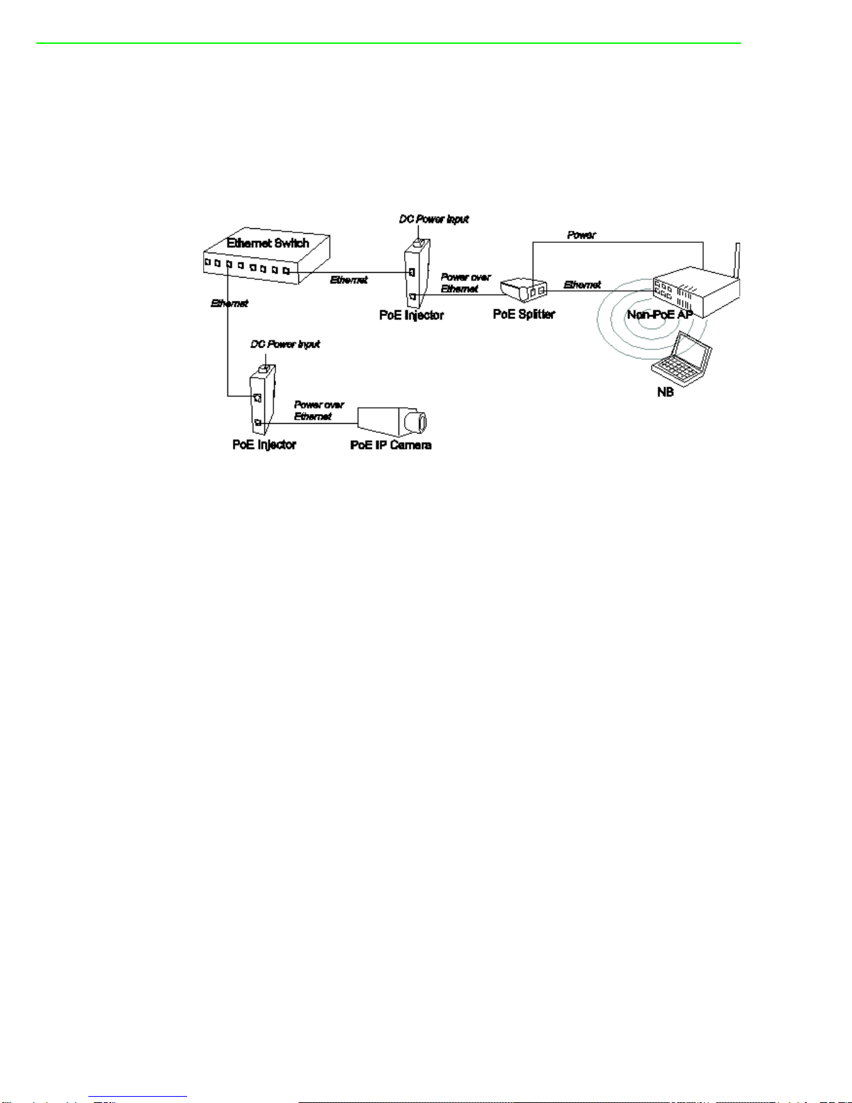
1.1 Introduction
The Industrial Power over Ethernet Injector provides data and DC power through the
Ethernet cable to PoE-equipped devices, such as IP camera, access point, PoE split-
ter or other equipment supporting IEEE 802.3at. The injector is typically installed
near the Ethernet switch. The figure below presents the example for the Power over
Ethernet Injector application.
1.2 Features
10/100/1000BaseT Power over Ethernet Injector
IEEE802.3at compliant
Provides power feeding up to 30 watts
Overload current protection
DC power input ranging from 24 ~ 48 V
Wide operating temperature -40 ~ 75°C

3 EKI-2701HPI-AE User Manual
Chapter 1 Overview
1.3 Specifications
Standard
IEEE802.3 10BASE-T
IEEE802.3u 100BASE-TX
IEEE802.3ab 1000Base-T
IEEE802.3af/at Power over Ethernet
Connector LAN port: Data/Signal pins 1, 2, 3, 6
PoE port: Data/Signal pins 1, 2, 3, 6
Power pins [1, 2 (V+)], [3, 6 (V-)]
Network Cable
10BASE-T: 2-pair UTP/STP Cat.3, 4,5 cable
EIA/TIA-568 100-ohm (100 m)
100BASE-TX: 2-pair UTP/STP Cat.5 cable (Cat. 5e recom-
mended)
EIA/TIA-568 100-ohm (100 m)
1000Base-T: 4-pair UTP/STP Cat. 5e or above cable
EIA/TIA-568 100-ohm (100 m)
LED Power x 2
PoE x 1
Power Input 24/48VDC
Power Consumption 33.36 watts @ 24 VDC
Operating Temperature -40oC ~ 75oC (-40o F ~ 167o F)
Storage Temperature -40oC ~ 85oC (-40o F ~ 185o F)
Operating/Storage
Humidity 5% ~ 95% Humidity (non-condensing)
Dimensions 36 mm x 140 mm x 95 mm (W x H x D)
EMC
■CE, FCC Class A
■EN61000-6-4
■EN61000-6-2
■EN61000-4-2 (ESD)
■EN61000-4-3 (RS)
■EN61000-4-4 (EFT)
■EN61000-4-5 (Surge)
■EN61000-4-6 (CS)
■EN61000-4-8 (Magnetic Field)
Safety UL508
EKI-2701HPI-AE User Manual 4
1.4 Packing List
1 x Power over Ethernet Injector
1 x Wall-mounting kit
1 x User Manual (CD-ROM)
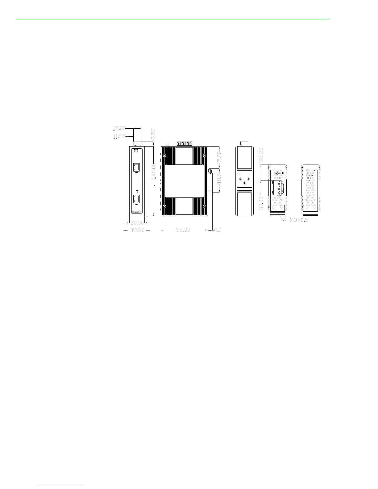
1.5 Dimensions
The Power over Ethernet Injector dimensions are 36 mm (W) x 140 mm (H) x 95 mm
(D).
Figure 1.1 Dimensions

Chapter 2
2Hardware Description
EKI-2701HPI-AE User Manual 6
2.1 Front Panel
On the front panel the Power over Ethernet Injector is equipped with two RJ-45 ports
and three LED indicators.
LAN port: It is an ordinary RJ-45 Ethernet port for data transmitting and receiv-
ing.
PoE port: It is an RJ-45 Ethernet port capable of supplying power over the
Ethernet cable as well as forwarding data to powered devices.
P1 & P2: The indicators light up when their respective power inputs are active.
PoE: This LED indicator lights up while power feeding works normally.
2.2 Top View
Designed with two power inputs, the PoE Injector allows users to supply redundant
power rating in the range of 24 to 48V.
2.3 Grounding the PoE Injector
Follow the instructions below to attach the PoE Injector to ground.
1. On the top of the device, locate and remove the dome screw which has a
ground symbol beside it.
2. Attach the ground wire to the screw hole with the dome screw.
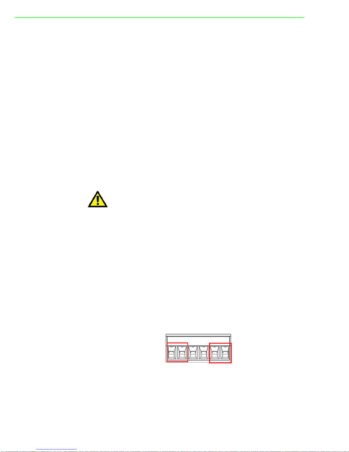
2.4 Wiring the Power Inputs
Please follow the steps below to wire power lines from the terminal block to the com-
pliant external DC power source.
1. Before wiring, make sure the power source is disconnected.
2. Using the wire-stripping tool, strip a short piece of insulation from the output
wires of the DC power source.
3. Identify the positive and negative feed positions for the terminal block connec-
tion. See the symbols printed on the panel indicating the polarities and DC input
power range in voltage.
Plugs for Power 1 & Power 2
4. Insert the exposed wires into the terminal block plugs. Only wires with insulation
should extend from the terminal block plugs. Note that the polarities between
the wires and the terminal block plugs must be positive to positive and negative
to negative.
5. Use a slotted screwdriver to tighten the captive screws.
Caution! When installing the PoE Injector, the ground connection must always be
made first and disconnected last.

7 EKI-2701HPI-AE User Manual
Chapter 2 Hardware Description
2.5 RJ-45 Pin Assignments
The UTP/STP ports will automatically sense for Fast Ethernet (10Base-T/100Base-
TX) or Gigabit Ethernet (10Base-T/100Base-TX/1000Base-T) connection. Auto MDI/
MDIX means that the port can connect to another switch or workstation without
changing straight through or crossover cabling. See the figures below for straight
through and crossover cable schema.
10/100Base-TX Pinouts
The table below shows the 10Base-T/100Base-TX MDI and MDI-X port pinouts.
10/100Base-TX Cable Schema
Straight Through Cable Schema
Crossover Cable Schema
Caution! Use Copper Conductors Only, 60/75 C, tightening to 5 lb-in
The wire gauge for the terminal block should be in the range between 12
~ 24 AWG.
Pin Number Assignment
1Tx+
2Tx-
3Rx+
6Rx-
Note! "+" and "-" signs represent the polarity of the wires that make up each
wire pair.
Pin Number MDI-X Signal Name MDI Signal Name
1 Receive Data plus (RD+) Transmit Data plus (TD+)
2 Receive Data minus (RD-) Transmit Data minus (TD-)
3 Transmit Data plus (TD+) Receive Data plus (RD+)
6 Transmit Data minus (TD-) Receive Data minus (RD-)

EKI-2701HPI-AE User Manual 8
10/100/1000Base-T Pinouts
The table below describes the gigabit Ethernet RJ-45 pinouts.
10/100/1000Base-T Cable Schema
The following two figures illustrate the 10/100/1000Base-T cable schema.
Straight Through Cable Schema
Crossover Cable Schema
Pin Signal name Description
1 BI_DA+ Bi-directional pair A+
2 BI_DA- Bi-directional pair A-
3 BI_DB+ Bi-directional pair B+
4 BI_DC+ Bi-directional pair C+
5 BI_DC- Bi-directional pair C-
6 BI_DB- Bi-directional pair B-
7 BI_DD+ Bi-directional pair D+
8 BI_DD- Bi-directional pair D-

Chapter 3
3Installation

EKI-2701HPI-AE User Manual 10
3.1 DIN-Rail Mounting
3.1.1 Assembling the DIN-Rail Clip
The DIN-rail clip is screwed on the device in the factory. If not, please refer to the fol-
lowing steps and figure to secure the DIN-rail clip on the device.
1. Use the screws to secure the DIN-rail clip at the rear of the device.
2. To remove the DIN-rail clip, reverse step 1.
3.1.2 Hanging the PoE Injector
Follow the steps below to hang the device on the standard DIN rail.
1. First, position the rear side of the unit directly in front of the DIN rail. Make sure
the top of the clip hooks over the top of the DIN rail.
11 EKI-2701HPI-AE User Manual
Chapter 3 Installation
2. Push the unit downward.
3. Check the DIN-Rail clip is tightly fixed on the DIN rail.
4. To remove the device from the track, reverse the steps above.
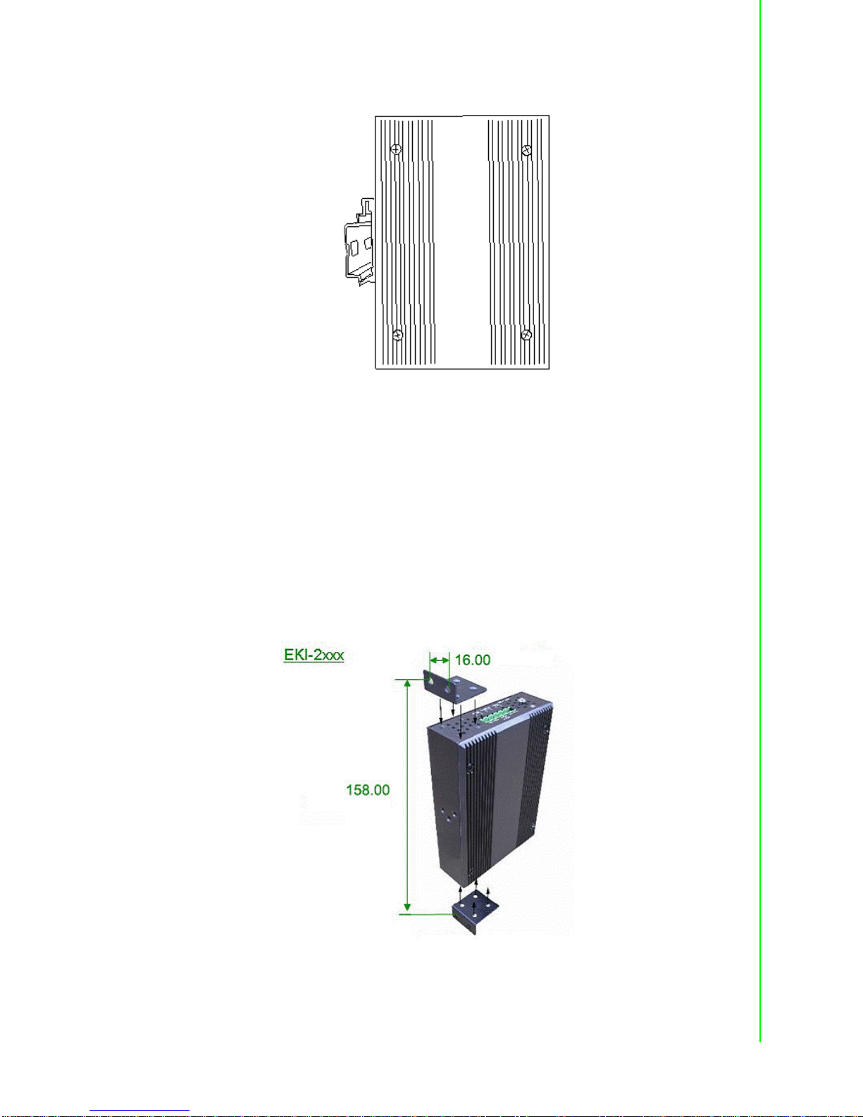
3.2 Wall-Mount Plate Mounting
Follow the steps below to mount the device with the wall-mount plates.
1. To remove the DIN-Rail clip from the device, unscrew the screws that secure it.
2. Align the screw holes of the wall-mount plates with the ones of the device.
3. Use the screws included to secure the wall-mount plates on the device.
4. Use the hook holes of the wall-mount plates to hang the device on the wall.
5. To remove the wall-mount plates, reverse the steps above.

EKI-2701HPI-AE User Manual 12

Chapter 4
4Troubleshooting

EKI-2701HPI-AE User Manual 14
4.1 Troubleshooting
Verify that you are using the right power cord/adapter. Please don't use a power
adapter with DC outputs higher than the power rating of this equipment, or it will
be damaged.
Select the proper UTP/STP cable for your network. Please check that you are
using the right cable. Use unshielded twisted-pair (UTP) or shielded twisted-pair
(STP) cable for the RJ-45 connections: 100ΩCategory 3, 4, or 5 cable for
10Mbps connections or 100ΩCategory 5 cable for 100Mbps connections. Also
be sure that the length of any twisted-pair connection does not exceed 100
meters (328 feet).
Diagnosing LED Indicators: The device can be easily monitored through LED
indicators, which describe common problems the user may encounter and
where the user can find possible solutions.
If the power indicator does not light up when the power cord is plugged in, you
may have a problem with power cord. Then check for loose power connections,
power losses or surges at the power outlet. If you still cannot resolve the prob-
lem, contact your local dealer for assistance.
If the cables are properly connected and the LED indicators show normal, but
the packets still cannot transmit, please check your system's Ethernet devices'
configuration or status.
Table of contents
Popular Laboratory Equipment manuals by other brands

Bruker
Bruker BioSpin 500'154 USP user manual

Heraeus
Heraeus Labofuge 300 Instructions for use

Sita
Sita IT Series MANUAL OF INSTALLATION, USE AND SERVICING

Ovation
Ovation QS Cleaning instructions

Miele professional
Miele professional PG 8583 CD operating instructions

Nippon Genetics Europe
Nippon Genetics Europe FastGene NG020 manual

DÜPERTHAL
DÜPERTHAL HSC UTS ergo operating instructions

Karl Suss
Karl Suss MA6 operating manual

REITEL
REITEL RETOCAST T operating instructions

Thermoline Scientific Equipment
Thermoline Scientific Equipment TFB-1 operating instructions

Thermo Scientific
Thermo Scientific Shandon TissueWave 2 Operator's guide

OSCAR
OSCAR MX Series User instructions


