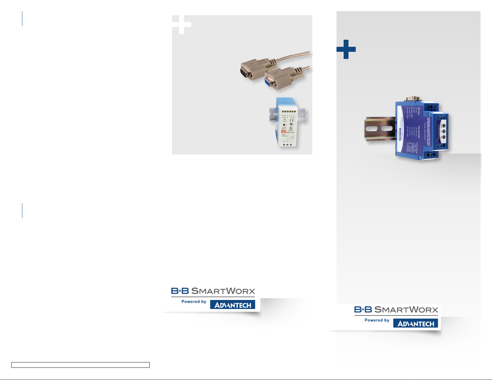
Recommended Accessories
Serial Cable
Model 9PAMF6
Industrial Power Supply
Model MDR-40-24
Document Number: 710-10764-00_r1_485LDRC9_3817qsg
1-888-948-2248 | Europe: +353 91 792444
advantech-bb.com
707 Dayton Road | PO Box 1040 | Ottawa, IL 61350
Phone: 815-433-5100 | Fax: 815-433-5109
www.advantech-bb.com | E-mail: support@advantech-bb.com
Before you begin, be sure
you have the following:
Model 485LDRC9
RS-232 to RS-422/485 Converter
Fast and easy on the web:
www.advantech-bb.com
+ Model 485LDRC9 Serial Converter
+ Required, but not included:
- Power Supply
- RS-232 Cable
- RS-422/485 Cable
QUICK START
GUIDE
Timing Issues?
(Usually applies when using RS-485 2-wire)
Model 485LDRC9 uses RC time constant. This means that when
you are setting the DIP switches for the “baud rate” you are setting a
turnaround time, not a “baud rate”.
Sometimes the turnaround time on an RS-485 2-wire device does not
match the turnaround time that is set on the 485LDRC9 converter,
even though they are both set for the same baud rate. Refer to the
chart in Step 3 to match the turnaround time of your RS-485 2-wire
device. If you do not know the turnaround time of your device, you can
do the following:
• Keep your device at its current baud rate, but change the
“baud rate” on the 485LDRC9. Set it for one or two steps
above or below the baud rate of your device until you get
communication.
• Alternatively, you can use the 485DRCi-PH instead of
the 485LDRC9. The 485DRCi-PH uses bitwise control so
you do not have to worry about matching the timing of your
device.
Note: Do not use the shield drain wire as the signal ground between
RS-422/485 devices. RS-422/485 systems may communicate
successfully without the signal ground when nodes are located
close together and circuit grounds for all nodes are at the same
potential--e.g., a controlled lab environment. However, this practice
is not recommended. If a signal ground is not used when nodes are
separated by distance, and there is the possibility of lightning and/
or other electrical noise, the common mode voltage can rise to
levels that could compromise communications, or even damage the
transceivers in the system nodes.
Troubleshooting
8
UL Installation Information
Underwriters Laboratories Conditions of Acceptability – When
installed in the end-use equipment, consideration should be
given to the following:
1. The wiring terminals are suitable for factory wiring only.
2. This device is to be mounted in a suitable enclosure in the
end-product.
3. This device is suitable for operation at a maximum
surrounding air temperature as described in the
documentation.
4. These devices are intended for use in a Pollution Degree 2
environment.
• Input Voltage: 10 – 30 VDC
• Input Power: 0.5 Watts
• Wire Range: 12 – 24 AWG
• Tightening Torque: 4 kgf-cm
• Temperature rating of eld installed conductors is 105 °C
minimum, sized for 60 °C ampacity.
• Use copper wire only.
• Maximum surrounding ambient air temperature 80 °C.
UL Installation Information
9


