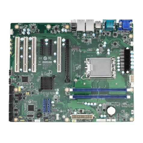
v ASMB-925 User Manual
Contents
Chapter 1 Overview...............................................1
1.1 Introduction ............................................................................................... 2
1.2 Features.................................................................................................... 2
1.3 Specifications............................................................................................ 3
Table 1.1: Specifications ............................................................. 3
1.4 Board Layout, Jumpers, and Connectors.................................................. 5
Figure 1.1 Board Layout .............................................................. 5
Figure 1.2 Rear I/O ...................................................................... 6
Table 1.2: Onboard LAN LED Color Definition ............................ 6
Table 1.3: Jumpers...................................................................... 7
Table 1.4: Connectors ................................................................. 7
Table 1.5: Onboard LED.............................................................. 8
1.5 Block Diagram........................................................................................... 9
Figure 1.3 Block Diagram ............................................................ 9
1.6 System Memory ........................................................................................ 9
1.7 Memory Installation................................................................................. 10
Table 1.6: DIMM Configuration with Single CPU....................... 10
Table 1.7: DIMM Configuration with Dual CPU ......................... 11
Table 1.8: DCPMM Population Matrix ....................................... 11
1.8 Processor Installation.............................................................................. 12
Chapter 2 Connections.......................................15
2.1 Introduction ............................................................................................. 16
2.2 USB and LAN Ports (USB1~USB11, LAN1~LAN4)................................ 16
2.3 VGA Connector (VGA1).......................................................................... 17
2.4 Serial Ports (COM1, COM2) ................................................................... 17
2.5 PS2 Keyboard and Mouse Connector (KBMS1) ..................................... 18
2.6 CPU Fan Connector (CPUFAN0, CPUFAN1)......................................... 18
2.7 System Fan Connector (SYSFAN0~SYSFAN4) ..................................... 19
2.8 Front Panel Connector (JFP1, JFP2, JFP3) ........................................... 19
2.8.1 Power LED (JFP3) ...................................................................... 20
Table 2.1: ATX Power Supply LED Status ................................ 20
2.8.2 External Speaker (JFP2 Pins 1, 4, 7, 10).................................... 20
2.8.3 HDD LED Connector (JFP1 Pins 2 & 5) ..................................... 20
2.8.4 Reset Connector (JFP1 Pins 9 & 12).......................................... 20
2.8.5 SNMP Connector (JFP1 Pins 8 & 11)......................................... 21
2.9 Case Open (JCASE1)............................................................................. 21
2.10 SATA SGPIO (SGPIO1).......................................................................... 22
2.11 Front Panel LAN Indicator Connector (LANLED1).................................. 22
2.12 Serial ATA Interface (SATA0~SATA7).................................................... 23
2.13 PCIe and PCI Expansion Slot ................................................................. 24
2.14 Auxiliary Power Connector (ATXPWR1, ATX12V1, ATX12V2) .............. 25
2.15 HD Audio Interface Connector (HDAUD1) .............................................. 26
2.16 LPC Connector (LPC1) for Optional TPM ............................................... 26
2.17 CMOS Clear and ME Update Connector (JCMOS1, JME1) ................... 27
2.18 PMBUS Connector (PMBUS1)................................................................ 27
2.19 Front Panel SMBUS Connector (SMBUS1)............................................ 28
2.20 IPMI Module Connector (BMC_CN1, BMC_CN2)................................... 28
2.21 VOLT1 Connector (VOLT1) .................................................................... 29
2.22 GPIO Connector (GPIO1) ....................................................................... 29
2.23 Intel Virtual RAID (VROC1)..................................................................... 30
2.24 NVMe RAID LED Control (PEHP1)......................................................... 30
