ADVANTEST R3131 Series User manual

MANUAL NUMBER
C
Printed in Japan
ADVANTEST CORPORATION
All rights reserved
.
R3131
Spectrum Analyzer
Operation Manual
FOE-8311227D02
1997 First printing December 1, 1997

R3131 Spectrum Analyzer Operation Manual
Preface-1
PREFACE
This manual provides the information necessary to check functionality, operate and program the R3131 Spectrum
Analyzer. Be sure to read this manual carefully in order to use the spectrum analyzer safely.
•Organization of this manual
This manual consists of the following chapters:
1. Introduction
• Product Description
• Standard Accessories and Power Cable Options
• Operating Environment
• Operation Check
• Cleaning, Storing and Transporting
Includes a description of the spec-
trum analyzer and its’ parts along
with information on its’ operating
environment and how to perform a
system checkout.
2. Operation
• Controls and Connectors on the Front and Rear
Panels
• Screen Annotation
• Basic Operation
• Measurement Examples
Describes the names and the func-
tions of each part on the panels. You
can learn the basic operation of the
spectrum analyzer through the exam-
ples shown in this chapter.
3. Reference
• Menu Index
• Menu Map
• Functional Description
Shows a list of operation keys, and
describes the function of each key.
4. Remote Control
•GPIB
•RS-232
Gives an outline of the GPIB and
RS-232 interfaces, and how to con-
nect and set them up. Also included
are a list of commands necessary for
programming and using the program
examples.
5. Specifications Shows the specifications of the spec-
trum analyzer.
APPENDIX 1. Error Messages If an error occurs during operation,
an error number and its correspond-
ing error message are displayed. The
meaning of each error is explained in
this section.
APPENDIX 2. Glossary Terminology related to the spectrum
analyzer is explained in this section.
Jul 10/98

R3131 Spectrum Analyzer Operation Manual
Preface
Preface-2* Jul 10/98
•Key notations in this manual
Typeface conventions used in this manual.
Panel keys: In bold type Example: MKR, MEAS
Soft keys: In bold and italic type Example: Normal Marker, Noise/Hz
The 1/2, more and 2/2, more soft keys are designated by 1/2_more and 2/2_more in Chapter 2.

R3131 Spectrum Analyzer Operation Manual
C-1
TABLE OF CONTENTS
1 INTRODUCTION
........................................................................................... 1-1
1.1 Product Description ............................................................................................. 1-1
1.2 Accessories .......................................................................................................... 1-2
1.3 Operating Environment ....................................................................................... 1-4
1.3.1 Environmental Conditions ............................................................................ 1-4
1.3.2 Power Requirements ..................................................................................... 1-5
1.3.3 Power Fuse .................................................................................................... 1-5
1.3.4 Power Cable .................................................................................................. 1-7
1.4 System Checkout ................................................................................................. 1-8
1.5 Cleaning, Storing and Transporting the R3131 Spectrum Analyzer ................... 1-11
1.5.1 Cleaning ........................................................................................................ 1-11
1.5.2 Storing ........................................................................................................... 1-12
1.5.3 Transporting .................................................................................................. 1-12
2 OPERATION
.................................................................................................... 2-1
2.1 Panel Description ................................................................................................. 2-1
2.1.1 Front Panel .................................................................................................... 2-1
2.1.2 Screen Annotation ......................................................................................... 2-10
2.1.3 Rear Panel ..................................................................................................... 2-12
2.2 Basic Operation ................................................................................................... 2-14
2.2.1 Operating Menus and Entering Data ............................................................ 2-14
2.2.2 Displaying Spectrums and Operating the Markers ....................................... 2-17
2.2.3 Measuring Window and the Display Line .................................................... 2-23
2.2.4 Measuring Frequency Using Counter ........................................................... 2-28
2.2.5 Auto Tuning .................................................................................................. 2-31
2.2.6 Tracking Operations ..................................................................................... 2-33
2.2.7 UNCAL Messages ........................................................................................ 2-36
2.2.8 Separating Two Signals ................................................................................ 2-39
2.2.9 Dynamic Range ............................................................................................. 2-42
2.2.10 Input Saturation ............................................................................................. 2-46
2.2.11 Harmonic Distortion ..................................................................................... 2-49
2.2.12 Intermodulation ............................................................................................. 2-52
2.2.13 Calibration .................................................................................................... 2-55
2.2.14 Entering User-definable Antenna Correction Data ....................................... 2-56
2.3 Measurement Examples ....................................................................................... 2-59
2.3.1 Measuring the Channel Power ...................................................................... 2-59
2.3.2 Measuring the Occupied Bandwidth (OBW) ................................................ 2-62
2.3.3 Measuring Adjacent Channel Leakage Power (ACP) .................................. 2-65
2.3.3.1 Measurements using the ACP POINT Method ......................................... 2-65
2.3.3.2 Measurements using the ACP GRAPH Method ....................................... 2-68
2.3.4 Measuring the VA Ratio ............................................................................... 2-71
Aug 28/98

R3131 Spectrum Analyzer Operation Manual
Table of Contents
C-2
2.3.5 Pass-Fail Judgments ...................................................................................... 2-74
2.3.6 Harmonic Distortion Measurements ............................................................. 2-78
2.3.7 Measurements Using TG (Option 74) .......................................................... 2-81
2.4 Other Functions ................................................................................................... 2-85
2.4.1 Using Floppy Disks ...................................................................................... 2-85
2.4.2 Saving or Recalling Data .............................................................................. 2-88
2.4.3 Outputting Screen Data ................................................................................. 2-95
2.4.4 Setting Date and Time .................................................................................. 2-99
3 REFERENCE
.................................................................................................... 3-1
3.1 Menu Index .......................................................................................................... 3-1
3.2 Menu Map ........................................................................................................... 3-7
3.3 Menu Function Descriptions ............................................................................... 3-16
3.3.1 AUTO TUNE Key (Auto Tuning) ................................................................ 3-16
3.3.2 BW Key (Bandwidth) ................................................................................... 3-17
3.3.3 CAL Key (Calibration) ................................................................................. 3-18
3.3.4 CONFIG Key (Configuration) ...................................................................... 3-19
3.3.5 COPY Key (Hard Copy) ............................................................................... 3-21
3.3.6 COUNTER Key (Frequency Counter) ......................................................... 3-22
3.3.7 DISPLAY Key (Line and Window) ............................................................. 3-23
3.3.8 EMC Key (EMC Measurement) ................................................................... 3-26
3.3.9 FREQ Key (Frequency) ................................................................................ 3-28
3.3.10 Hold Mode .................................................................................................... 3-29
3.3.11 LEVEL Key (Frequency Level) ................................................................... 3-30
3.3.12 LOCAL Key (GPIB Remote Control) .......................................................... 3-32
3.3.13 MEAS Key (Measurement) .......................................................................... 3-33
3.3.14 MKR Key (Marker) ...................................................................................... 3-35
3.3.15 MKR
→Key (Marker →) ............................................................................ 3-38
3.3.16 PAS/FAIL Key (Pass-Fail Judgment) ........................................................... 3-40
3.3.17 PK SRCH Key (Peak Search) ....................................................................... 3-41
3.3.18 POWER MEASURE Key (Power Measurement) ........................................ 3-42
3.3.19 PRESET Key (Initialization) ........................................................................ 3-44
3.3.20 RECALL Key (Data Readout) ...................................................................... 3-45
3.3.21 REPEAT Key (Continuous Sweep) .............................................................. 3-46
3.3.22 SAVE Key (Saving Data) ............................................................................. 3-47
3.3.23 SELF TEST Key (Self Test) ......................................................................... 3-48
3.3.24 SINGLE Key (Single Sweep) ....................................................................... 3-49
3.3.25 SPAN Key (Frequency Span) ....................................................................... 3-50
3.3.26 SWEEP Key (Sweep Time) .......................................................................... 3-51
3.3.27 TG Key (Tracking Generator) (Option 74) ................................................... 3-52
3.3.28 TRACE Key (Trace Data) ............................................................................ 3-54
3.3.29 TRIG Key (Trigger) ...................................................................................... 3-56
3.4 Setting Values ...................................................................................................... 3-57
Aug 28/98

R3131 Spectrum Analyzer Operation Manual
Table of Contents
C-3*
3.4.1 Set Resolution ............................................................................................... 3-57
3.4.2 Set Values for RBW, VBW and SWP Time ................................................. 3-58
3.4.3 Factory Defaults ............................................................................................ 3-59
3.4.4 Defaults Configuration Values ..................................................................... 3-60
4 REMOTE PROGRAMING
........................................................................... 4-1
4.1 GPIB Remote Programming ................................................................................ 4-1
4.1.1 GPIB ............................................................................................................. 4-1
4.1.2 GPIB Setup ................................................................................................... 4-1
4.1.3 GPIB Interface Functions ............................................................................. 4-3
4.1.4 Responses to Interface Messages .................................................................. 4-3
4.1.5 Message Exchange Protocol ......................................................................... 4-5
4.1.6 Command Syntax .......................................................................................... 4-6
4.1.7 Data Formats ................................................................................................. 4-6
4.1.8 Status Bytes ................................................................................................... 4-8
4.1.9 GPIB Command Codes ................................................................................. 4-14
4.1.10 Basic Programming ....................................................................................... 4-31
4.1.11 Data Output Format (talker) ......................................................................... 4-33
4.1.12 Trace Data I/O .............................................................................................. 4-37
4.1.13 Using the Status Byte .................................................................................... 4-42
4.2 RS-232 Remote Control Function ....................................................................... 4-46
4.2.1 GPIB and RS-232 Compatibility .................................................................. 4-46
4.2.2 Features of RS-232 Remote Control ............................................................. 4-46
4.2.3 Parameter Setup Window ............................................................................. 4-46
4.2.4 Interface connection ...................................................................................... 4-47
4.2.5 Data Format .................................................................................................. 4-49
4.2.6 Differences Between RS-232 and GPIB ....................................................... 4-50
4.2.7 Panel Control ................................................................................................ 4-50
4.2.8 Remote Control Usage Examples ................................................................. 4-50
5 SPECIFICATIONS
.......................................................................................... 5-1
APPENDIX 1 ERROR MESSAGE ..................................................................... A1-1
APPENDIX 2 GLOSSARY ................................................................................... A2-1
DIMENSIONAL OUTLINE DRAWING .......................................................... EXT-1
ALPHABETICAL INDEX .................................................................................... I-1
Aug 28/98


F-1
R3131 Spectrum Analyzer Operation Manual
LIST OF ILLUSTRATIONS
No. Title Page
1-1 Operating Environment ..................................................................................................... 1-4
1-2 Replacing the Power Fuse ................................................................................................. 1-6
1-3 Power Cable ...................................................................................................................... 1-7
1-4 Connecting the Power Supply Cable ................................................................................ 1-8
1-5 Screen Display after Self Tests have Completed .............................................................. 1-9
1-6 Self Test Screen ................................................................................................................ 1-9
1-7 Screen Shown after Executing Self Test ........................................................................... 1-10
1-8 Removing the Display Filter ............................................................................................. 1-11
2-1 Front Panel ........................................................................................................................ 2-1
2-2 Screen Annotation ............................................................................................................. 2-10
2-3 Rear Panel ......................................................................................................................... 2-12
2-4 Factory Defaults Screen .................................................................................................... 2-18
2-5 Calibration Signal Output Screen ..................................................................................... 2-18
2-6 Active Area Display .......................................................................................................... 2-19
2-7 Setting the Center Frequency ............................................................................................ 2-19
2-8 Measuring Settings Screen ................................................................................................ 2-20
2-9 Peak Search Display Screen ............................................................................................. 2-21
2-10 Frequency Difference Between the Peak Point and a Point 3 dB Levels Down .............. 2-22
2-11 Frequency Difference Between the Peak Point and a Point 60 dB Levels Down ............ 2-22
2-12 Factory Defaults Screen ....................................................................................................2-23
2-13 Calibration Signal Output ................................................................................................. 2-24
2-14 Measuring Settings Screen ................................................................................................ 2-24
2-15 Activating the Display Line .............................................................................................. 2-25
2-16 Making a Comparison Between Peaks Using Reference Lines ........................................ 2-26
2-17 Screen Display Showing the Measuring Window ............................................................ 2-27
2-18 Screen Display after Zoom In ........................................................................................... 2-27
2-19 Factory Defaults Screen ....................................................................................................2-28
2-20 Calibration Signal Output Screen ..................................................................................... 2-29
2-21 Measuring Settings Screen ................................................................................................ 2-29
2-22 Frequency Counter Measurement (Resolution: 1 kHz) .................................................... 2-30
2-23 Frequency Counter Measurement (Resolution: 10 Hz) .................................................... 2-30
2-24 Screen Display Prior to Auto Tuning ............................................................................... 2-31
2-25 Screen Display after Auto Tuning .................................................................................... 2-32
2-26 Signal Tracking Screen .....................................................................................................2-34
2-27 Continuous Peak Search Screen ....................................................................................... 2-35
2-28 Measuring Settings Screen ................................................................................................ 2-37
2-29 Screen with UNCAL Message .......................................................................................... 2-37
2-30 Normal Measurement Screen ............................................................................................ 2-38
2-31 Setup for Measuring Two Signals Separately ................................................................... 2-39
2-32 Two Superimposed Peaks ................................................................................................. 2-40
2-33 Two Discernible Peaks ..................................................................................................... 2-41
2-34 Two Distinct Peaks Can Now Be Seen ............................................................................. 2-41
2-35 Setup for Verifying the Dynamic Range .......................................................................... 2-42
2-36 Screen Display Prior to Changing the RBW .................................................................... 2-43
2-37 Screen Display after Changing the RBW ......................................................................... 2-44
Aug 28/98

F-2
R3131 Spectrum Analyzer Operation Manual
List of Illustrations
No. Title Page
2-38 Screen Display after Changing the VBW ......................................................................... 2-44
2-39 The Trace after Averaging ................................................................................................ 2-45
2-40 Setup for Input Saturation .................................................................................................2-46
2-41 Screen Display without Saturation ................................................................................... 2-47
2-42 Screen Display Showing Saturation ................................................................................. 2-48
2-43 Setup for Measuring Harmonic Distortion ....................................................................... 2-49
2-44 Screen Display Showing Harmonic Distortion ................................................................. 2-50
2-45 Screen Display Showing Reduced Harmonic Distortion .................................................. 2-51
2-46 Setup for Measuring Intermodulation ............................................................................... 2-52
2-47 Screen Display Showing Intermodulation Distortion ....................................................... 2-53
2-48 Screen Display without Intermodulation Distortion ......................................................... 2-54
2-49 Screen Display Showing the Cal Menu ............................................................................ 2-55
2-50 Editing the Correction Data Table .................................................................................... 2-57
2-51 Screen Display Showing the User-Definable Correction Data Table ............................... 2-58
2-52 Setup for Measuring the Channel Power .......................................................................... 2-59
2-53 Setting the Offset Level .................................................................................................... 2-60
2-54 Setting the Measuring Window ........................................................................................ 2-61
2-55 Measuring the Channel Power .......................................................................................... 2-61
2-56 Setup for Measuring the Occupied Bandwidth ................................................................. 2-62
2-57 Setting the Detector Mode ................................................................................................ 2-63
2-58 OBW Measurement Screen .............................................................................................. 2-64
2-59 OBW(95%) Measurement Screen .................................................................................... 2-64
2-60 Setup for Measuring the Adjacent Channel Leakage Power ............................................ 2-65
2-61 Setting the Specified Bandwidth ....................................................................................... 2-67
2-62 Measurement of the Adjacent Channel Power (ACP POINT) ......................................... 2-67
2-63 Setup for Measuring the Adjacent Channel Leakage Power ............................................ 2-68
2-64 Displaying a Graph as a Result of Operation ................................................................... 2-70
2-65 Adjacent Channel Leakage Power Measurements (ACP GRAPH) .................................. 2-70
2-66 Setup for Measuring the VA Ratio ................................................................................... 2-71
2-67 Performing Max Hold ....................................................................................................... 2-72
2-68 Measuring the Video Carrier Level .................................................................................. 2-73
2-69 Measuring the Audio Carrier Level .................................................................................. 2-73
2-70 Setup for the Pass-Fail judgment ...................................................................................... 2-74
2-71 Pass-Fail Measurement Screen ......................................................................................... 2-75
2-72 Level Window Setting Screen .......................................................................................... 2-76
2-73 Measuring Window Screen ............................................................................................... 2-76
2-74 Setup for Measuring the Harmonic Distortion ................................................................. 2-78
2-75 Measuring the Fundamental Wave ................................................................................... 2-79
2-76 Measuring the Harmonic Distortion ................................................................................. 2-80
2-77 Setup for TG Measurements ............................................................................................. 2-81
2-78 Measurement Screen after a Normalization Calibration ................................................... 2-82
2-79 Connecting the Unit under Test ........................................................................................ 2-83
2-80 Insertion Loss Measurement Screen ................................................................................. 2-84
2-81 3-dB Bandwidth Measurement Screen ............................................................................. 2-84
2-82 Floppy Disk Write Protection ........................................................................................... 2-85
2-83 Screen for the F.Disk Menu .............................................................................................. 2-87
2-84 Screen Display Showing Floppy Disk as the Destination ................................................ 2-88
2-85 Display for Selecting the Data to be Saved ...................................................................... 2-89
Aug 28/98

R3131 Spectrum Analyzer Operation Manual
List of Illustrations
F-3*
No. Title Page
Aug 28/98
2-86 Display after Data has been Saved to a File ..................................................................... 2-90
2-87 Screen Display Showing File Protection Enabled ............................................................ 2-91
2-88 Screen Display Showing the Selected File ....................................................................... 2-92
2-89 Screen Display showing Recalled Data ............................................................................ 2-92
2-90 Screen as Shown when Deleting a File ............................................................................. 2-93
2-91 Screen as Shown after Deleting File Data ........................................................................ 2-94
2-92 Screen Display Showing Floppy Disk as the Specified Destination ................................ 2-95
2-93 Printer Specification Screen Display ................................................................................ 2-97
2-94 Printer Setup Screen .......................................................................................................... 2-98
2-95 Time/Date Menu ............................................................................................................... 2-99
2-96 Screen Showing the Date being Set .................................................................................. 2-100
2-97 Screen Showing the Hour being Set ................................................................................. 2-100
4-1 Arrangement of the Three Status Registers ...................................................................... 4-9
4-2 Details of the Three Status Registers ................................................................................ 4-10
4-3 Structure of the Status Byte Register ................................................................................ 4-12
4-4 Parameter Setup ................................................................................................................ 4-46
4-5 Connection Between the Controller and the Spectrum Analyzer ..................................... 4-47
4-6 Cable Wiring Diagram ...................................................................................................... 4-48
4-7 Data Format ...................................................................................................................... 4-49
A2-1 Resolution Bandwidth .......................................................................................................A2-1
A2-2 Reference Level ................................................................................................................ A2-1
A2-3 Spurious Response ............................................................................................................ A2-3
A2-4 Noise Sidebands ................................................................................................................ A2-4
A2-5 Bandwidth Selectivity ....................................................................................................... A2-4
A2-6 Bandwidth Switching Accuracy ....................................................................................... A2-5


T-1*
R3131 Spectrum Analyzer Operation Manual
LIST OF TABLES
No. Title Page
1-1 Standard Accessories List ................................................................................................. 1-2
1-2 Power Cable Options ........................................................................................................1-3
1-3 Power Supply Specifications ............................................................................................ 1-5
2-1 Recommended Compatible Printers ................................................................................. 2-96
3-1 Center Frequency Set Resolution vs. Frequency Span ..................................................... 3-57
3-2 Frequency Span Set Resolution vs. Frequency Span ........................................................ 3-57
3-3 Values for RBW, VBW and SWP Time (using AUTO) .................................................. 3-58
3-4 Factory Defaults ................................................................................................................ 3-59
3-5 Values for Default Config ................................................................................................. 3-60
4-1 Frequency .......................................................................................................................... 4-14
4-2 Level ................................................................................................................................. 4-15
4-3 Unit ................................................................................................................................... 4-15
4-4 Sweep Mode ..................................................................................................................... 4-16
4-5 Sweep Time ...................................................................................................................... 4-16
4-6 Bandwidth ......................................................................................................................... 4-16
4-7 Marker ............................................................................................................................... 4-17
4-8 Peak Search ....................................................................................................................... 4-18
4-9 Sound ................................................................................................................................ 4-18
4-10 Marker →.......................................................................................................................... 4-19
4-11 Trigger .............................................................................................................................. 4-19
4-12 Trace ................................................................................................................................. 4-20
4-13 Display .............................................................................................................................. 4-21
4-14 Pass-Fail Judgment ........................................................................................................... 4-22
4-15 Measurement ..................................................................................................................... 4-22
4-16 Auto Tuning ...................................................................................................................... 4-22
4-17 Counter .............................................................................................................................. 4-23
4-18 Power Measurement .........................................................................................................4-23
4-19 OBW ................................................................................................................................. 4-23
4-20 ACP ................................................................................................................................... 4-24
4-21 TG (Option 74) ................................................................................................................. 4-24
4-22 EMC .................................................................................................................................. 4-25
4-23 Calibration ........................................................................................................................ 4-26
4-24 Data Save/Recall ............................................................................................................... 4-26
4-25 Hard Copy ......................................................................................................................... 4-28
4-26 Preset ................................................................................................................................. 4-28
4-27 Trace Data I/O .................................................................................................................. 4-28
4-28 Status Bytes ....................................................................................................................... 4-28
4-29 Miscellaneous ................................................................................................................... 4-29
4-30 Data Input ......................................................................................................................... 4-30
Aug 28/98


R3131 Spectrum Analyzer Operation Manual
1.1 Product Description
1-1Jul 10/98
1 INTRODUCTION
This chapter provides the following information:
• Product description
• A list of standard accessories and power cable options
• Operating environment
• How to verify that the spectrum analyzer is functioning properly
• How to clean, store, and transport the spectrum analyzer
1.1 Product Description
The R3131 is a spectrum analyzer that provides the user with highly stable spectrum analysis using the syn-
thesized local method.
The key features of the R3131 spectrum analyzer are listed below.
(1) Frequency Range: 9kHz to 3GHz, Frequency span: Zero, 50kHz to 3GHz.
(2) Frequency counter function with a resolution of 1Hz.
(3) A power measurement function useful for evaluating radio instruments using measurements such as
occupied bandwidth (OBW), adjacent channel power (ACP), channel power, etc.
(4) An auto tuning function that searches for a signal with the maximum input level.
(5) Save and recall functions which you can use to store measurement conditions and data in TEXT for-
mat.
(6) A 3.5-inch floppy disk drive which you can use to save screen images in BMP format.
(7) Support for ESC/P, ESC/P-R and PCL compatible printers.
(8) Remote control capabilities which allow you to setup an automatic measurement system. This re-
mote control function complies with GPIB and RS-232 specifications.

R3131 Spectrum Analyzer Operation Manual
1.2 Accessories
1-2 Aug 28/98
1.2 Accessories
Table 1-1 lists the standard accessories shipped with the spectrum analyzer. If any of the accessories are dam-
aged or missing or, to order additional accessories, contact the nearest ADVANTEST Field Office or repre-
sentative.
Table 1-1 Standard Accessories List
* 1: The cable supplied with the spectrum analyzer depends on what type (specified by model
number above) was ordered when the spectrum analzyer was purchased.
There are 11 types of power cable available (see Table 1-2).
To order another power cable, contact an ADVANTEST Field Office or representative. When
ordering, refer to power cables by their option number or model number.
* 2: Quantity is 2 when the instrument is equipped with TG option (Option 74).
Accessory Name Model Number Quantity Remarks
Power cable A01413 1 * 1
N-BNC through connector JUG-201A/U 1 * 2
R3131 Spectrum Analyzer
Operation Manual ER3131 1

R3131 Spectrum Analyzer Operation Manual
1.2 Accessories
1-3Dec 1/97
Table 1-2 Power Cable Options
*1 CEE: Europe, DEMKO: Denmark, NEMKO: Norway, VED: Germany,
KEMA: The Netherlands, CBEC: Belgium, OVE: Austria, FIMKO: Finland,
SEMKO: Sweden
JIS: Japan 125V at 7A Straight: A01402
Law on Electrical Appliances Black
2m (6ft) Angled: A01412
UL: United States of America 125V at 7A Straight: A01403
CSA: Canada Black (Option 95)
2m (6ft) Angled: A01413
*1 250V at 6A Straight: A01404
Gray (Option 96)
2m (6ft) Angled: A01414
SEV: Switzerland 250V at 6A Straight: A01405
Gray (Option 97)
2m (6ft) Angled: A01415
SAA: Australia, New Zealand 250V at 6A Straight: A01406
Gray (Option 98)
2m (6ft) Angled: ---------
BS: United Kingdom 250V at 6A Straight: A01407
Black (Option 99)
2m (6ft) Angled: A01417
Plug Standards Rating, Color Model Number

R3131 Spectrum Analyzer Operation Manual
1.3 Operating Environment
1-4 Jul 10/98
1.3 Operating Environment
This section describes the environmental conditions and power requirements necessary to use the spectrum
analyzer.
1.3.1 Environmental Conditions
The R3131 should be only be used in an area which satisfies the following conditions:
• Ambient temperature: 0°C to +50°C (operating temperature)
• Relative humidity: 85% or less (without condensation)
• An area free from corrosive gas
• An area away from direct sunlight
• A dust-free area
• An area free from vibrations
• A low noise area
Although the R3131 has been designed to withstand a certain amount of noise riding on the AC
power line, it should be used in an area of low noise. Use a noise cut filter when ambient noise is una-
voidable.
• An area allowing unobstructed air flow
The R3131 has an exhaust cooling fan on the rear panel and an exhaust vent on the bottom side
toward the front. Never block these areas as the resulting internal temperature rise will affect meas-
urement accuracy.
Figure 1-1 Operating Environment
Line Filter
Vibration
Direct sunlight
Corrosive
gas
• Avoid operation in the following areas. • Use a noise cut filter when there is a large
amount of noise riding on the power line.
• Keep the rear panel 10cm away
from the wall
Front
Dust

R3131 Spectrum Analyzer Operation Manual
1.3 Operating Environment
1-5Jul 10/98
The R3131 can be used safely under the following conditions:
• Altitude: 2000m maximum above the sea level
• Installation category II
• Pollution degree 2
1.3.2 Power Requirements
The power supply specifications of the spectrum analyzer are listed in Table 1-3.
Table 1-3 Power Supply Specifications
CAUTION:To prevent damage, operate the spectrum analyzer within the specified input voltage and frequency
ranges.
During operation, the power supply automatically switches between input voltage levels of 100VAC and
200VAC. Be sure, however, to use a power cable that matches the input voltage and meets the related
standard (see Table 1-2).
1.3.3 Power Fuse
CAUTION:When a fuse blows, there may be some problem with the analyzer so contact a qualified ADVANTEST
service representative before replacing the fuse.
The power fuse is placed in the fuse holder which is mounted on the rear panel. A spare fuse is located in
the fuse holder.
To check or replace the power fuse, use the following procedure:
1. Press the POWER switch to the OFF position.
2. Disconnect the power cable from the AC power supply.
3. Remove the fuse holder on the rear panel.
4. Check (and replace if necessary) the power fuse and put it back in the fuse holder.
100VAC Operation 200VAC Operation
Input voltage range 90V to 132V 198V to 250V
Frequency range 48Hz to 66Hz
Power consumption 200VA or below

R3131 Spectrum Analyzer Operation Manual
1.3 Operating Environment
1-6 Apr 10/98
Figure 1-2 Replacing the Power Fuse
Fuse holder
Pull out the fuse holder using a slotted
head screwdriver.
Fuse (T5A compliant)
Check (and replace if
necessary) the power fuse and
put it back into the fuse holder.
Spare fuse attached to the fuse holder.
Fuse holder

R3131 Spectrum Analyzer Operation Manual
1.3 Operating Environment
1-7Apr 10/98
1.3.4 Power Cable
A detachable power cable with a three-contact plug is included with the spectrum analyzer. The protective
earth ground contact on the plug connects (through the power cable) to the accessible metal parts of the
instrument. For protection against electrical shock, insert the plug into a power-source outlet that has a
properly grounded, protective-ground contact.
The manufacturer ships a power cable, as ordered, with the spectrum analyzer. A list of other available
power cables is shown in Table 1-2. Contact your ADVANTEST representative or the local ADVAN-
TEST Field Office for information on how to order these.
Figure 1-3 Power Cable
3-pin power cable
Ground pin
To AC power outlet
Other manuals for R3131 Series
1
Table of contents
Other ADVANTEST Measuring Instrument manuals
ADVANTEST
ADVANTEST R3765G Series User manual
ADVANTEST
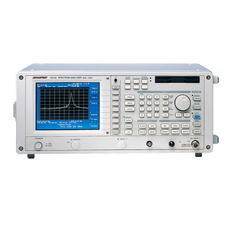
ADVANTEST R3132 Series User manual
ADVANTEST
ADVANTEST R3267 series User manual
ADVANTEST
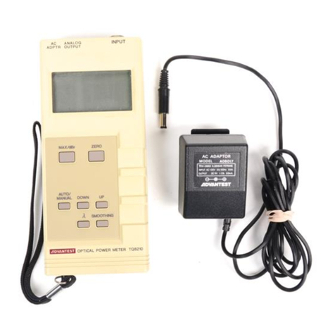
ADVANTEST TQ8210 User manual
ADVANTEST
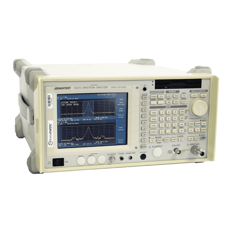
ADVANTEST R3267 series User manual
ADVANTEST
ADVANTEST R3465 Series User manual
ADVANTEST
ADVANTEST R3131 Series User manual
ADVANTEST
ADVANTEST R3267 series User manual

ADVANTEST
ADVANTEST R3755 Series User manual
ADVANTEST
ADVANTEST R3261C Installation manual
