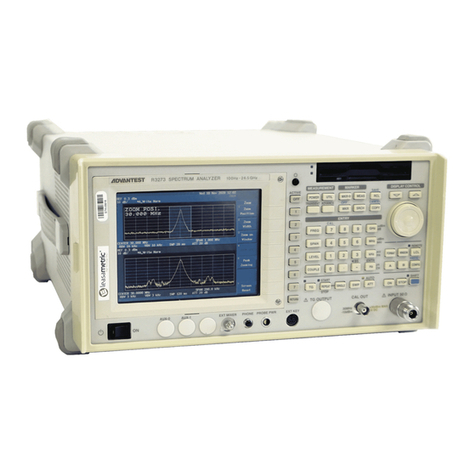
ADVANTEST R3132 Series User manual

MANUAL NUMBER
CPrinted in Japan
ADVANTEST CORPORATION
All rights reserved.
R3132 Series
Spectrum Analyzer
Operation Manual
FOE-8335156H00
1999 First printing March 20, 1999
Applicable models
R3132
R3132N
R3162
R3172
R3182
Cover

No. ESE00
Safety-1
Safety Summary
To ensure thorough understanding of all functions and to ensure efficient use of this instrument, please read the
manual carefully before using. Note that Advantest bears absolutely no responsibility for the result of operations
caused due to incorrect or inappropriate use of this instrument.
If the equipment is used in a manner not specified by Advantest, the protection provided by the equipment may
be impaired.
• Warning Labels
Warning labels are applied to Advantest products in locations where specific dangers exist. Pay
careful attention to these labels during handling. Do not remove or tear these labels. If you have
any questions regarding warning labels, please ask your nearest Advantest dealer. Our address
and phone number are listed at the end of this manual.
Symbols of those warning labels are shown below together with their meaning.
DANGER: Indicates an imminently hazardous situation which will result in death or serious
personal injury.
WARNING: Indicates a potentially hazardous situation which will result in death or serious
personal injury.
CAUTION: Indicates a potentially hazardous situation which will result in personal injury or
a damage to property including the product.
• Basic Precautions
Please observe the following precautions to prevent fire, burn, electric shock, and personal inju-
ry.
• Use a power cable rated for the voltage in question. Be sure however to use a power cable
conforming to safety standards of your nation when using a product overseas.
• When inserting the plug into the electrical outlet, first turn the power switch OFF and then
insert the plug as far as it will go.
• When removing the plug from the electrical outlet, first turn the power switch OFF and then
pull it out by gripping the plug. Do not pull on the power cable itself. Make sure your hands
are dry at this time.
• Before turning on the power, be sure to check that the supply voltage matches the voltage
requirements of the instrument.
• Be sure to plug the power cable into an electrical outlet which has a safety ground terminal.
Grounding will be defeated if you use an extension cord which does not include a safety
ground terminal.
• Be sure to use fuses rated for the voltage in question.
• Do not use this instrument with the case open.
Safety Summary

Safety Summary
Safety-2
• Do not place objects on top of this product. Also, do not place flower pots or other containers
containing liquid such as chemicals near this product.
• When the product has ventilation outlets, do not stick or drop metal or easily flammable ob-
jects into the ventilation outlets.
• When using the product on a cart, fix it with belts to avoid its drop.
• When connecting the product to peripheral equipment, turn the power off.
• Caution Symbols Used Within this Manual
Symbols indicating items requiring caution which are used in this manual are shown below to-
gether with their meaning.
DANGER: Indicates an item where there is a danger of serious personal injury (death or seri-
ous injury).
WARNING: Indicates an item relating to personal safety or health.
CAUTION: Indicates an item relating to possible damage to the product or instrument or relat-
ing to a restriction on operation.
• Safety Marks on the Product
The following safety marks can be found on Advantest products.
: ATTENTION - Refer to manual.
: Protective ground (earth) terminal.
: DANGER - High voltage.
: CAUTION - Risk of electric shock.

Safety Summary
Safety-3
• Replacing Parts with Limited Life
The following parts used in the instrument are main parts with limited life.
Replace the parts listed below after their expected lifespan has expired.
Note that the estimated lifespan for the parts listed below may be shortened by factors such as
the environment where the instrument is stored or used, and how often the instrument is used.
There is a possibility that each product uses different parts with limited life. For more informa-
tion, refer to Chapter 1.
Main Parts with Limited Life
• Precautions when Disposing of this Instrument
When disposing of harmful substances, be sure dispose of them properly with abiding by the
state-provided law.
Harmful substances: (1) PCB (polycarbon biphenyl)
(2) Mercury
(3) Ni-Cd (nickel cadmium)
(4) Other
Items possessing cyan, organic phosphorous and hexadic chromium
and items which may leak cadmium or arsenic (excluding lead in sol
der).
Example: fluorescent tubes, batteries
Part name Life
Unit power supply 5 years
Fan motor 5 years
Electrolytic capacitor 5 years
LCD panel 6 years
LCD backlight 2.5 years
Floppy disk drive 5 years

Environmental Conditions
Safety-4
This instrument should be only be used in an area which satisfies the following conditions:
• An area free from corrosive gas
• An area away from direct sunlight
• A dust-free area
• An area free from vibrations
Figure-1 Environmental Conditions
• Instrument Placement
Figure-2 Instrument Placement
This instrument can be used safely under the following conditions:
• Altitude of up to 2000 m
• Installation Categories II
• Pollution Degree 2
Vibration
Direct sunlight
Corrosive
gas
Dust
Front
Keep at least 10 centimeters of space
between the rear panel and any other
surface

R3132 Series Spectrum Analyzer Operation Manual
Cautions-1
CAUTIONS
The front two feet beneath the front panel have small extensions which can be used to pro-
vide a better viewing angle (12-degree tilt).
Note the following when using the extensions:
• Use the analyzer on flat surfaces so that the weight of the analyzer is evenly distributed.
• Do not put any objects on the analyzer.
• Do not lean on the analyzer.
• Do not place anything (hands or other objects) under the analyzer.
• Do not slide the analyzer.
• Do not use excessive force when pressing keys (more than 1 kg).
Make sure the extensions are folded shut when:
• Transporting the analyzer.
• Connecting or disconnecting cables.
• Using the analyzer on a cart.
• The analyzer is not in use.
• The analyzer is in storage.
Do not use the extensible feet if they show signs of excessive wear.
• The extensions may wear out over time. If this occurs, contact ADVANTEST or our service agency
for information on how to replace them.
CAUTIONS

Certificate of Conformity
This is to certify, that
complies with the provisions of the EMC Directive 89/336/EEC in accordance with
EN61326 and Low Voltage Directive 73/23/EEC in accordance with EN61010.
ADVANTEST Corp. ROHDE&SCHWARZ
Tokyo, Japan Engineering and Sales GmbH
Munich, Germany
instrument, type, designation
3132.03
Spectrum Analyzer
R3132 Series
Certificate of Conformity

R3132 Series Spectrum Analyzer Operation Manual
Preface-1
PREFACE
This manual provides the information necessary to check functionality, operate and program the R3132 Series
Spectrum Analyzer. Be sure to read this manual carefully in order to use the spectrum analyzer safely.
•Organization of this manual
This manual consists of the following chapters:
1. INTRODUCTION
• Product Description
• Accessories
•Options
• Operating Environment
• System Checkout
• Cleaning, Storing and Transporting the R3132
Series Spectrum Analyzer
• Calibration
• Replacing Parts with Limited Life
Includes a description of the
spectrum analyzer and its’ parts
along with information on its’
operating environment and how to
perform a system checkout.
2. OPERATION
• Panel Description
• Basic Operation
• Measurement Examples
• Other Functions
Describes the names and the
functions of each part on the panels.
You can learn the basic operation of
the spectrum analyzer through the
examples shown in this chapter.
3. REFERENCE
• Menu Index
• Menu Map
• Menu Function Descriptions
• List of Settings
Shows a list of operation keys, and
describes the function of each key.
4. REMOTE PROGRAMMING
• GPIB Command Index
• GPIB Remote Programming
• RS-232 Remote Control Function
Gives an outline of the GPIB and
RS-232 interfaces, and how to
connect and set them up. Also
included are a list of commands
necessary for programming and
using the program examples.
5. PERFORMANCE VERIFICATION
• General
• Procedures of Performance Verification
• Tracking Generator Performance Verification
Procedure
• Performance Verification for OPT73 (FM
Demodulation)
• Performance Verification Record Sheet
Describes the performance verifica-
tion.
6. PERFORMANCE VERIFICATION (External Mixer)
• External Mixer OPT16
• External Mixer OPT17
• External Mixer OPT18
• External Mixer OPT19
Describes the performance verifica-
tion(External Mixer).
PREFACE

R3132 Series Spectrum Analyzer Operation Manual
Preface
Preface-2
•Key notations in this manual
Typeface conventions used in this manual.
Panel keys: In bold type Example: MKR, MEAS
Soft keys: In bold and italic type Example: Normal, Noise/Hz
The 1/2, more and 2/2, more soft keys are designated by 1/2_more and 2/2_more in this
manual.
7. SPECIFICATIONS
• R3132 Specifications
• R3132N Specifications
• R3162 Specifications
• R3172 Specifications
• R3182 Specifications
•Options
Shows the specifications of the
spectrum analyzer.

R3132 Series Spectrum Analyzer Operation Manual
C-1
TABLE OF CONTENTS
1 INTRODUCTION ............................................................................................ 1-1
1.1 Product Description ............................................................................................. 1-1
1.2 Accessories .......................................................................................................... 1-3
1.3 Options ................................................................................................................ 1-5
1.4 Operating Environment ....................................................................................... 1-6
1.4.1 Environmental Conditions ............................................................................ 1-6
1.4.2 Power Requirements ..................................................................................... 1-7
1.4.3 Power Fuse .................................................................................................... 1-7
1.4.4 Power Cable .................................................................................................. 1-9
1.5 System Checkout ................................................................................................. 1-10
1.6 Cleaning, Storing and Transporting the R3132 Series Spectrum Analyzer ........ 1-13
1.6.1 Cleaning ........................................................................................................ 1-13
1.6.2 Storing ........................................................................................................... 1-14
1.6.3 Transporting .................................................................................................. 1-14
1.7 Calibration ........................................................................................................... 1-15
1.8 Replacing Parts with Limited Life ...................................................................... 1-15
2 OPERATION .................................................................................................... 2-1
2.1 Panel Description ................................................................................................. 2-1
2.1.1 Front Panel .................................................................................................... 2-1
2.1.2 Screen Annotation ......................................................................................... 2-12
2.1.3 Rear Panel ..................................................................................................... 2-14
2.2 Basic Operation ................................................................................................... 2-16
2.2.1 Operating Menus and Entering Data ............................................................ 2-16
2.2.2 Displaying Spectrums and Operating the Markers ....................................... 2-19
2.2.3 Measuring Window and the Display Line .................................................... 2-24
2.2.4 Measuring Frequency Using Counter ........................................................... 2-27
2.2.5 Auto Tuning .................................................................................................. 2-29
2.2.6 Tracking Operations ..................................................................................... 2-31
2.2.7 UNCAL Message .......................................................................................... 2-33
2.2.8 Separating Two Signals ................................................................................ 2-35
2.2.9 Measuring low level signals ......................................................................... 2-38
2.2.10 Input Saturation ............................................................................................. 2-42
2.2.11 Harmonic Distortion ..................................................................................... 2-44
2.2.12 Intermodulation ............................................................................................. 2-46
2.2.13 Calibration .................................................................................................... 2-49
2.2.14 Entering User-definable Antenna Correction Data ....................................... 2-49
2.2.15 External Mixer (OPT16 thru OPT19) ........................................................... 2-52
2.3 Measurement Examples ....................................................................................... 2-55
2.3.1 Measuring the Channel Power ...................................................................... 2-55
2.3.2 Measuring the Occupied Bandwidth (OBW) ................................................ 2-58
TABLE OF CONTENTS

R3132 Series Spectrum Analyzer Operation Manual
Table of Contents
C-2
2.3.3 Measuring Adjacent Channel Leakage Power (ACP) .................................. 2-61
2.3.3.1 Full Screen Mode ........................................................................................ 2-61
2.3.3.2 SEPARATE Display ................................................................................... 2-67
2.3.4 Measuring Burst Signals Using the Gated Sweep ........................................ 2-71
2.3.5 Measuring Burst Signals in the Time Domain .............................................. 2-75
2.3.6 Pass/Fail Judgments Using the Limit line Function ..................................... 2-79
2.3.7 Measurements Using TG (OPT74) ............................................................... 2-85
2.3.8 Spectrum Mask Measurement ...................................................................... 2-89
2.3.9 Measuring Output Levels Using the Software Image Suppression function
(OPT16 thru OPT19) .................................................................................... 2-94
2.3.10 FM Demodulation Function (OPT73) .......................................................... 2-97
2.4 Other Functions ................................................................................................... 2-104
2.4.1 Using Floppy Disks ...................................................................................... 2-104
2.4.2 Saving or Recalling Data .............................................................................. 2-107
2.4.3 Outputting Screen Data ................................................................................. 2-115
2.4.4 Setting Date and Time .................................................................................. 2-118
2.4.5 Setting the Screen Title ................................................................................. 2-119
3 REFERENCE .................................................................................................... 3-1
3.1 Menu Index .......................................................................................................... 3-1
3.2 Menu Map ........................................................................................................... 3-7
3.3 Menu Function Descriptions ............................................................................... 3-19
3.3.1 AUTO TUNE Key (Auto Tuning) ................................................................ 3-19
3.3.2 BW Key (Bandwidth) ................................................................................... 3-20
3.3.3 CAL Key (Calibration) ................................................................................. 3-21
3.3.4 CONFIG Key (Configuration) ...................................................................... 3-23
3.3.5 COPY Key (Hard Copy) ............................................................................... 3-29
3.3.6 COUNTER Key (Frequency Counter) ......................................................... 3-30
3.3.7 DISPLAY Key (Line and Window) ............................................................. 3-31
3.3.8 EMC Key (EMC Measurement) ................................................................... 3-33
3.3.9 FREQ Key (Frequency) ................................................................................ 3-36
3.3.10 Hold Mode .................................................................................................... 3-41
3.3.11 LEVEL Key (Frequency Level) ................................................................... 3-42
3.3.12 LOCAL Key (GPIB Remote Control) .......................................................... 3-44
3.3.13 MEAS Key (Measurement) .......................................................................... 3-45
3.3.14 MKR Key (Marker) ...................................................................................... 3-50
3.3.15 MKR →Key (Marker →) ............................................................................ 3-53
3.3.16 PAS/FAIL Key (Pass/Fail Judgment) ........................................................... 3-54
3.3.17 PK SRCH Key (Peak Search) ....................................................................... 3-56
3.3.18 POWER MEASURE Key (Power Measurement) ........................................ 3-57
3.3.19 PRESET Key (Initialization) ........................................................................ 3-66
3.3.20 RECALL Key (Data Readout) ...................................................................... 3-67
3.3.21 REPEAT Key (Continuous Sweep) .............................................................. 3-68

R3132 Series Spectrum Analyzer Operation Manual
Table of Contents
C-3
3.3.22 SAVE Key (Saving Data) ............................................................................. 3-69
3.3.23 Self Test Key (Self Test) .............................................................................. 3-71
3.3.24 SINGLE Key (Single Sweep) ....................................................................... 3-72
3.3.25 SPAN Key (Frequency Span) ....................................................................... 3-73
3.3.26 SWEEP Key (Sweep Time) .......................................................................... 3-74
3.3.27 TG Key (Tracking Generator) (OPT74) ....................................................... 3-76
3.3.28 TRACE Key (Trace Data) ............................................................................ 3-77
3.3.29 TRIG Key (Trigger) ...................................................................................... 3-81
3.3.30 UTILITY Key (Utility) ................................................................................. 3-83
3.4 List of Settings ..................................................................................................... 3-85
3.4.1 Factory Defaults ............................................................................................ 3-85
3.4.2 Defaults Configuration Values ..................................................................... 3-89
4 REMOTE PROGRAMING ........................................................................... 4-1
4.1 GPIB Command Index ........................................................................................ 4-1
4.2 GPIB Remote Programming ................................................................................ 4-8
4.2.1 GPIB ............................................................................................................. 4-8
4.2.2 GPIB Setup ................................................................................................... 4-9
4.2.3 GPIB Interface Functions ............................................................................. 4-10
4.2.4 Responses to Interface Messages .................................................................. 4-11
4.2.5 Message Exchange Protocol ......................................................................... 4-12
4.2.6 Command Syntax .......................................................................................... 4-13
4.2.7 Data Formats ................................................................................................. 4-14
4.2.8 Status Byte .................................................................................................... 4-15
4.2.9 GPIB Command Codes ................................................................................. 4-22
4.2.10 Example Programs ........................................................................................ 4-49
4.2.10.1 Sample Programs for Setting or Reading Measurement Conditions ........ 4-49
4.2.10.2 Sample Programs for Reading Data .......................................................... 4-51
4.2.10.3 Sample Programs for Inputting or Outputting Trace Data ....................... 4-56
4.2.10.4 Example program using the TS (Take Sweep) command ........................ 4-60
4.2.10.5 Program Examples Using the Status Byte ................................................ 4-61
4.2.10.6 Example Program Used to Read Screen Data .......................................... 4-62
4.3 RS-232 Remote Control Function ....................................................................... 4-63
4.3.1 GPIB and RS-232 Compatibility .................................................................. 4-63
4.3.2 Features of RS-232 Remote Control ............................................................. 4-63
4.3.3 Parameter Setup Window ............................................................................. 4-63
4.3.4 Interface connection ...................................................................................... 4-64
4.3.5 Data Format .................................................................................................. 4-65
4.3.6 Differences Between RS-232 and GPIB ....................................................... 4-66
4.3.7 Panel Control ................................................................................................ 4-66
4.3.8 Remote Control Usage Examples ................................................................. 4-67
5 PERFORMANCE VERIFICATION .......................................................... 5-1

R3132 Series Spectrum Analyzer Operation Manual
Table of Contents
C-4
5.1 General ................................................................................................................ 5-1
5.2 Procedures of Performance Verification ............................................................. 5-7
5.2.1 Frequency Reference Source Output Accuracy ............................................ 5-7
5.2.2 Calibrator Amplitude Accuracy .................................................................... 5-9
5.2.3 Displayed Average Noise Level ................................................................... 5-11
5.2.4 Resolution Bandwidth Switching Uncertainty ............................................. 5-16
5.2.5 Resolution Bandwidth Accuracy and Selectivity ......................................... 5-19
5.2.6 QP Bandwidth Accuracy .............................................................................. 5-23
5.2.7 IF Gain Uncertainty ...................................................................................... 5-25
5.2.8 Input Attenuator Switching Accuracy (R3132/32N/62) ............................... 5-29
5.2.9 Input Attenuator Switching Accuracy (R3172/82) ....................................... 5-32
5.2.10 Scale Fidelity ................................................................................................ 5-35
5.2.11 Residual FM .................................................................................................. 5-41
5.2.12 Noise Sidebands ............................................................................................ 5-45
5.2.13 Image, Multiple and Out-of-Band Responses ............................................... 5-47
5.2.14 Accuracy of Frequency Readout and Count Frequency Marker .................. 5-51
5.2.15 Second Harmonic Distortion ........................................................................ 5-55
5.2.16 Frequency Response ..................................................................................... 5-59
5.2.17 Frequency Span Accuracy ............................................................................ 5-68
5.2.18 Third Order Intermodulation Distortion ....................................................... 5-72
5.2.19 Gain Compression ......................................................................................... 5-77
5.2.20 Sweep Time Accuracy .................................................................................. 5-83
5.2.21 Residual Response ........................................................................................ 5-86
5.3 Tracking Generator Performance Verification Procedure ................................... 5-90
5.3.1 Absolute Output Level Accuracy ................................................................. 5-90
5.3.2 Output Level Flatness ................................................................................... 5-92
5.3.3 Output Level Switching Accuracy ................................................................ 5-95
5.3.4 Harmonic Distortion ..................................................................................... 5-102
5.3.5 Non Harmonic Distortion ............................................................................. 5-105
5.3.6 TG Leakage ................................................................................................... 5-107
5.4 Performance Verification for OPT73 (FM Demodulation) ................................. 5-109
5.4.1 Offset Error (Internal Mixer Mode) .............................................................. 5-109
5.4.2 Linearity Error (Internal Mixer Mode) ......................................................... 5-111
5.4.3 Offset Error (External Mixer Mode) ............................................................. 5-114
5.4.4 Linearity Error (External Mixer Mode) ........................................................ 5-116
5.5 Performance Verification Record Sheet .............................................................. 5-119
6 PERFORMANCE VERIFICATION (External Mixer) .......................... 6-1
6.1 External Mixer OPT16 ........................................................................................ 6-1
6.1.1 External Mixer Performance Verification Test Procedures .......................... 6-3
6.1.1.1 Noise Level ................................................................................................. 6-3
6.1.1.2 Frequency Response ................................................................................... 6-5
6.1.2 Performance Verification Test Record Sheets .............................................. 6-9

R3132 Series Spectrum Analyzer Operation Manual
Table of Contents
C-5
6.2 External Mixer OPT17 ........................................................................................ 6-14
6.2.1 External Mixer Performance Verification Test Procedures .......................... 6-16
6.2.1.1 Noise Level ................................................................................................. 6-16
6.2.1.2 Frequency Response ................................................................................... 6-18
6.2.2 Performance Verification Test Record Sheets .............................................. 6-22
6.3 External Mixer OPT18 ........................................................................................ 6-29
6.3.1 External Mixer Performance Verification Test Procedures .......................... 6-31
6.3.1.1 Noise Level ................................................................................................. 6-31
6.3.1.2 Frequency Response ................................................................................... 6-34
6.3.2 Performance Verification Test Record Sheets .............................................. 6-39
6.4 External Mixer OPT19 ........................................................................................ 6-52
6.4.1 External Mixer Performance Verification Test Procedures .......................... 6-54
6.4.1.1 Noise Level ................................................................................................. 6-54
6.4.1.2 Frequency Response ................................................................................... 6-56
6.4.2 Performance Verification Test Record Sheets .............................................. 6-60
7 SPECIFICATIONS .......................................................................................... 7-1
7.1 R3132 Specifications ........................................................................................... 7-1
7.2 R3132N Specifications ........................................................................................ 7-5
7.3 R3162 Specifications ........................................................................................... 7-9
7.4 R3172 Specifications ........................................................................................... 7-14
7.5 R3182 Specifications ........................................................................................... 7-19
7.6 Options ................................................................................................................ 7-25
APPENDIX ................................................................................................................ A-1
A.1 ERROR MESSAGE ............................................................................................ A-1
DIMENSIONAL OUTLINE DRAWING .......................................................... EXT-1
ALPHABETICAL INDEX .................................................................................... I-1

F-1
R3132 Series Spectrum Analyzer Operation Manual
LIST OF ILLUSTRATIONS
No. Title Page
1-1 Operating Environment ..................................................................................................... 1-6
1-2 Replacing the Power Fuse ................................................................................................. 1-8
1-3 Power Cable ...................................................................................................................... 1-9
1-4 Connecting the Power Supply Cable ................................................................................ 1-10
1-5 Screen Display after Self Tests have Completed .............................................................. 1-11
1-6 Self Test Screen ................................................................................................................ 1-11
1-7 Screen Shown after Executing Self Test ........................................................................... 1-12
1-8 Removing the Display Filter ............................................................................................. 1-13
2-1 Front Panel (R3132/32N/62) ............................................................................................ 2-1
2-2 Front Panel (R3172) .......................................................................................................... 2-2
2-3 Front Panel (R3182) .......................................................................................................... 2-2
2-4 Screen Annotation ............................................................................................................. 2-12
2-5 Rear Panel ......................................................................................................................... 2-14
2-6 Factory Defaults Screen ....................................................................................................2-20
2-7 Active Area Display .......................................................................................................... 2-21
2-8 Setting the Center Frequency ............................................................................................ 2-21
2-9 Measuring Settings Screen ................................................................................................ 2-22
2-10 Peak Search Display Screen ............................................................................................. 2-22
2-11 Activating the Display Line .............................................................................................. 2-25
2-12 Making a Comparison Between Peaks Using Reference Lines ........................................ 2-25
2-13 Screen Display Showing the Measuring Window ............................................................ 2-26
2-14 Measuring Settings Screen ................................................................................................ 2-28
2-15 Frequency Counter Measurement (Resolution: 1 kHz) .................................................... 2-28
2-16 Frequency Counter Measurement (Resolution: 10 Hz) .................................................... 2-29
2-17 Screen Display Prior to Auto Tuning ............................................................................... 2-30
2-18 Screen Display after Auto Tuning .................................................................................... 2-30
2-19 Signal Tracking Screen ..................................................................................................... 2-32
2-20 Continuous Peak Search Screen ....................................................................................... 2-33
2-21 Screen with UNCAL Message .......................................................................................... 2-34
2-22 UNCAL Message Removed ............................................................................................. 2-35
2-23 Setup for Measuring Two Signals Separately ................................................................... 2-35
2-24 Two Superimposed Peaks ................................................................................................. 2-36
2-25 Two Discernible Peaks .....................................................................................................2-37
2-26 Two Distinct Peaks Can Now Be Seen ............................................................................. 2-37
2-27 Setup for Verifying the Dynamic Range .......................................................................... 2-38
2-28 Screen Display Prior to Changing the RBW .................................................................... 2-39
2-29 Screen Display after Changing the RBW ......................................................................... 2-39
2-30 Screen Display after Changing the VBW ......................................................................... 2-40
2-31 The Trace after Averaging ................................................................................................ 2-40
2-32 Spectrum Displayed when the pre-amplifier is Used ....................................................... 2-41
2-33 Setup for Input Saturation ................................................................................................. 2-42
2-34 Screen Display without Saturation ................................................................................... 2-43
2-35 Screen Display Showing Saturation ................................................................................. 2-44
2-36 Setup for Measuring Harmonic Distortion ....................................................................... 2-44
2-37 Screen Display Showing Harmonic Distortion ................................................................. 2-45

F-2
R3132 Series Spectrum Analyzer Operation Manual
List of Illustrations
No. Title Page
2-38 Screen Display Showing Reduced Harmonic Distortion .................................................. 2-46
2-39 Setup for Measuring Intermodulation ............................................................................... 2-46
2-40 Screen Display Showing Intermodulation Distortion ....................................................... 2-48
2-41 Screen Display without Intermodulation Distortion ......................................................... 2-48
2-42 Screen Display Showing the Cal Menu ............................................................................ 2-49
2-43 Editing the Correction Data Table .................................................................................... 2-50
2-44 Screen for the EMC Menu ................................................................................................ 2-51
2-45 Screen Display Showing the User-Definable Correction Data Table ............................... 2-51
2-46 Setup for the R3172 and Waveguide Mixer ..................................................................... 2-53
2-47 Setup for the R3182 and Waveguide Mixer ..................................................................... 2-53
2-48 Setup for Measuring the Channel Power .......................................................................... 2-55
2-49 Setting the Offset Level .................................................................................................... 2-56
2-50 Measuring the Channel power .......................................................................................... 2-57
2-51 Setup for Measuring the Occupied Bandwidth ................................................................. 2-58
2-52 Setting the Detector Mode ................................................................................................ 2-59
2-53 OBW Measurement Screen .............................................................................................. 2-60
2-54 OBW(95%) Measurement Screen .................................................................................... 2-60
2-55 Setup Measuring Adjacent Channel Leakage Power ........................................................ 2-62
2-56 PDC trace .......................................................................................................................... 2-63
2-57 CS/BS Setup dialog box ................................................................................................... 2-64
2-58 Root Nyquist Filter dialog box ......................................................................................... 2-65
2-59 ACP Measurement Display in Full Screen Mode ............................................................. 2-65
2-60 Measurement Using ACP GRAPH ................................................................................... 2-66
2-61 ACP at the 100 kHz .......................................................................................................... 2-66
2-62 Setup Measuring Adjacent Channel Leakage Power ........................................................ 2-67
2-63 PHS Trace ......................................................................................................................... 2-68
2-64 CS/BS Setup dialog box ................................................................................................... 2-69
2-65 Measurement Result in ACP Separate Screen Mode ........................................................ 2-70
2-66 Setup for Measuring a Burst Signal .................................................................................. 2-71
2-67 Burst Signal Displayed in Split Screen Mode .................................................................. 2-72
2-68 Trigger Setup .................................................................................................................... 2-73
2-69 Gate Setup ......................................................................................................................... 2-73
2-70 Burst Signal by Use of the Gated Sweep (Separate Screen Mode) .................................. 2-74
2-71 Burst Signal by Use of the Gated Sweep (Full Screen Mode) .......................................... 2-74
2-72 Setup for Measuring a Burst wave signal ......................................................................... 2-75
2-73 Burst Signal in the Time Domain ..................................................................................... 2-76
2-74 Burst Signal in the Time Domain ..................................................................................... 2-76
2-75 Burst Signal in Synchronization with the Trigger Signal ................................................. 2-77
2-76 Measuring Burst Signal Leading Edge ............................................................................. 2-77
2-77 Measuring Burst Signal Trailing Edge ............................................................................. 2-78
2-78 Screen Displayed after Limit Line 1 Data Has Been Entered .......................................... 2-81
2-79 Screen Displayed after Limit Line 2 Data Has Been Entered .......................................... 2-81
2-80 PASS/FAIL Result using Limit Line 1 (PASS) ................................................................ 2-82
2-81 PASS/FAIL Result using Limit Lines 1 and 2 (FAIL) ..................................................... 2-82
2-82 PASS/FAIL Result using Limit Lines 1 and 2 (PASS) .................................................... 2-83
2-83 Judgment Result after the Offset Has Been Changed (FAIL) .......................................... 2-83
2-84 Judgment Result after the Offset Has Been Changed (PASS) .......................................... 2-84
2-85 Setup for TG Measurements ............................................................................................. 2-85

R3132 Series Spectrum Analyzer Operation Manual
List of Illustrations
F-3
No. Title Page
2-86 Measurement Screen after a Normalization Calibration ................................................... 2-86
2-87 Connecting the Unit under Test ........................................................................................ 2-87
2-88 Insertion Loss Measurement Screen ................................................................................. 2-88
2-89 3-dB Bandwidth Measurement Screen ............................................................................. 2-88
2-90 Setup for Measuring the Spectrum Mask ......................................................................... 2-89
2-91 A Trace Used with IS-95 .................................................................................................. 2-91
2-92 CS/BS Setup Dialog Box .................................................................................................. 2-92
2-93 Spectrum Mask Measurement Screen ............................................................................... 2-93
2-94 Setup for measuring VCO Output Levels ......................................................................... 2-94
2-95 Measurement Signal with an Image Signal ...................................................................... 2-95
2-96 Measurement Signal with the Image Signal Eliminated ................................................... 2-95
2-97 Software Image Suppression Function in Split Screen Mode .......................................... 2-96
2-98 Setup for Measurements Using the FM Demodulation Function ..................................... 2-97
2-99 FM Deviation Measurement ............................................................................................. 2-99
2-100 How to Calculate the Sensitivity ...................................................................................... 2-99
2-101 Sensitivity Measurement Screen ....................................................................................... 2-100
2-102 Simultaneously Displaying Sensitivity and Demodulation .............................................. 2-101
2-103 Setting Offset and Slope Used for Linearity Measurements ............................................ 2-101
2-104 Setting Offset and Slope when Using the Measuring Window ........................................ 2-102
2-105 Linearity Measurement ..................................................................................................... 2-102
2-106 Floppy Disk Write Protection ........................................................................................... 2-104
2-107 Screen for the F.Disk Menu .............................................................................................. 2-106
2-108 Screen Display Showing Floppy Disk as the Destination ................................................ 2-108
2-109 Display for Selecting the Data to be Saved ...................................................................... 2-109
2-110 Display after Data has been Saved to a File ..................................................................... 2-110
2-111 Screen Display Showing File Protection Enabled ............................................................ 2-111
2-112 Screen Display Showing the Selected File ....................................................................... 2-112
2-113 Screen Display showing Recalled Data ............................................................................ 2-112
2-114 Screen as Shown when Deleting a File ............................................................................. 2-113
2-115 Screen as Shown after Deleting File Data ........................................................................ 2-114
2-116 Screen Display Showing Floppy Disk as the Specified Destination ................................ 2-115
2-117 Printer Setup Screen .......................................................................................................... 2-117
2-118 Time/Date Menu ............................................................................................................... 2-118
2-119 Dialog Box Used to Enter Titles ....................................................................................... 2-119
2-120 Displaying the Screen Title ............................................................................................... 2-120
4-1 Arrangement of the Three Status Registers ...................................................................... 4-16
4-2 Details of the Three Status Registers ................................................................................ 4-17
4-3 Structure of the Status Byte Register ................................................................................ 4-19
4-4 Relationship between Screen Graticule and Trace Data ................................................... 4-56
4-5 Parameter Setup ................................................................................................................ 4-63
4-6 Connection Between the Controller and the Spectrum Analyzer ..................................... 4-64
4-7 Cable Wiring Diagram ...................................................................................................... 4-65
4-8 Data Format ...................................................................................................................... 4-65
5-1 Setup of Frequency Reference Source Accuracy Test ...................................................... 5-8
5-2 Setup of CAL OUT Level Accuracy Test ........................................................................ 5-10
5-3 Setup of Displayed Average Noise Level Test ................................................................. 5-12

F-4
R3132 Series Spectrum Analyzer Operation Manual
List of Illustrations
No. Title Page
5-4 Setup of Resolution Bandwidth Switching Uncertainty ................................................... 5-16
5-5 Setup of Resolution Bandwidth Accuracy and Selectivity Test ....................................... 5-20
5-6 Setup of QP Bandwidth Accuracy Test ............................................................................ 5-23
5-7 Setup of IF Gain Uncertainty Test .................................................................................... 5-26
5-8 Setup of Input Attenuator Switching Accuracy Test (R3132/32N/62) ............................. 5-29
5-9 Setup of Input Attenuator Switching Accuracy Test (R3172/82) ..................................... 5-33
5-10 Setup of Scale Fidelity Test ..............................................................................................5-36
5-11 Setup of Residual FM Test ............................................................................................... 5-42
5-12 Setup of Noise Sidebands Test ......................................................................................... 5-46
5-13 Setup of Image, Multiple and Out-of-Band Responses Test ............................................ 5-48
5-14 Setup of Accuracy of Frequency Readout and Frequency Counter Test .......................... 5-52
5-15 Setup of Second Harmonic Distortion Test ...................................................................... 5-56
5-16 Setup of Frequency Response Test ................................................................................... 5-61
5-17 Setup of Frequency Span Accuracy Test .......................................................................... 5-68
5-18 Setup of Third Order Intermodulation Distortion Test ..................................................... 5-74
5-19 Setup of Gain Compression Test ...................................................................................... 5-79
5-20 Setup of Sweep Time Accuracy Test ................................................................................ 5-83
5-21 Setup of Residual Response Test ...................................................................................... 5-87
5-22 Setup of Absolute Output Level Accuracy Test ............................................................... 5-90
5-23 Setup of Output Level Flatness Test ................................................................................. 5-92
5-24 Setup of Output Switching Accuracy Test ....................................................................... 5-96
5-25 Setup of Harmonic Distortion Test ................................................................................... 5-102
5-26 Setup of Non Harmonic Distortion Test ........................................................................... 5-105
5-27 Setup of TG Leakage Test ................................................................................................ 5-107
5-28 Setup for Checking the Offset Error (Internal Mixer Mode) ............................................ 5-109
5-29 Setup for Checking the Linearity Error (Internal Mixer Mode) ....................................... 5-111
5-30 Setup for Checking the Offset Error (External Mixer Mode) ........................................... 5-114
5-31 Setup for Checking the Linearity Error (External Mixer Mode) ...................................... 5-116
6-1 Setup of Noise Level Test ................................................................................................. 6-3
6-2 Setup of Source Module Calibration ................................................................................ 6-5
6-3 Setup of Frequency Response Test ................................................................................... 6-6
6-4 Setup of Noise Level Test ................................................................................................. 6-16
6-5 Setup of Source Module Calibration ................................................................................ 6-18
6-6 Setup of Frequency Response Test ................................................................................... 6-19
6-7 Setup of Noise Level Test ................................................................................................. 6-31
6-8 Setup of Source Module Calibration ................................................................................ 6-34
6-9 Setup of Frequency Response Test ................................................................................... 6-35
6-10 Setup of Noise Level Test .................................................................................................6-54
6-11 Setup of Source Module Calibration ................................................................................ 6-56
6-12 Setup of Frequency Response Test ................................................................................... 6-57

T-1
R3132 Series Spectrum Analyzer Operation Manual
LIST OF TABLES
No. Title Page
1-1 Standard Accessories List .................................................................................................1-3
1-2 Power Cable Options ........................................................................................................ 1-4
1-3 Power Supply Specifications ............................................................................................ 1-7
2-1 Product Summary ............................................................................................................. 2-52
2-2 Configuration of the Options ............................................................................................ 2-52
2-3 File Names ........................................................................................................................ 2-54
2-4 Setting Limit Line 1 .......................................................................................................... 2-80
2-5 Setting Limit Line 2 .......................................................................................................... 2-80
2-6 Setting Limit Line1 ........................................................................................................... 2-90
2-7 Relationship Between Frequency Range and the Value of RBW .................................... 2-98
2-8 Recommended Compatible Printers ................................................................................. 2-116
3-1 Factory Defaults (R3132/N) ............................................................................................. 3-85
3-2 Factory Defaults (R3162) ................................................................................................. 3-86
3-3 Factory Defaults (R3172) ................................................................................................. 3-87
3-4 Factory Defaults (R3182) ................................................................................................. 3-88
3-5 Values for Default Config .................................................................................................3-89
4-1 Frequency (1 of 3) ............................................................................................................. 4-22
4-2 Level ................................................................................................................................. 4-25
4-3 BW .................................................................................................................................... 4-25
4-4 Sweep ............................................................................................................................... 4-26
4-5 Trigger ............................................................................................................................. 4-27
4-6 Trace (1 of 2) ................................................................................................................... 4-28
4-7 Pass/Fail ............................................................................................................................ 4-30
4-8 Display ............................................................................................................................. 4-31
4-9 MKR (1 of 2) .................................................................................................................... 4-32
4-10 MKR →............................................................................................................................ 4-34
4-11 Meas (1 of 3) ..................................................................................................................... 4-35
4-12 Auto Tune ......................................................................................................................... 4-38
4-13 Counter .............................................................................................................................. 4-38
4-14 Power (1 of 3) .................................................................................................................. 4-38
4-15 EMC .................................................................................................................................. 4-41
4-16 CAL ................................................................................................................................. 4-42
4-17 Save Recall ...................................................................................................................... 4-43
4-18 Config .............................................................................................................................. 4-44
4-19 Preset ................................................................................................................................ 4-44
4-20 Test .................................................................................................................................... 4-45
4-21 GPIB ................................................................................................................................ 4-45
4-22 Others ................................................................................................................................ 4-46
4-23 FM Demodulation (OPT73) (1 of 2) ................................................................................. 4-46
4-24 TG (OPT74) ...................................................................................................................... 4-47
4-25 Entry ................................................................................................................................. 4-48
4-26 Trace Accuracy Specification Codes ................................................................................ 4-56
4-27 I/O format ......................................................................................................................... 4-57

T-2
R3132 Series Spectrum Analyzer Operation Manual
List of Tables
No. Title Page
5-1 Performance Verification Items ........................................................................................ 5-1
5-2 Performance Verification Items for Tracking Generator .................................................. 5-2
5-3 Performance Verification Items for FM Demodulation ................................................... 5-2
5-4 Instrument Required (1 of 3) ............................................................................................ 5-4
5-4 Center Frequency Setting for Display Average Noise Level ........................................... 5-13
5-5 Start and Stop Frequencies Setting ................................................................................... 5-15
5-6 RBW Switching Uncertainty Test Setting ........................................................................ 5-18
5-7 RBW and Span for 3 dB Down Width Measurement Setting .......................................... 5-21
5-8 RBW Selectivity Test Setting ........................................................................................... 5-22
5-9 RBW and Span for 6 dB Down Width Measurement Setting .......................................... 5-24
5-10 IF Gain Uncertainty Measurement Setting ....................................................................... 5-28
5-11 Input Attenuator Switching Accuracy Test Setting for R3132/32N ................................. 5-31
5-12 Input Attenuator Switching Accuracy Test Setting for R3162 ......................................... 5-31
5-13 Input Attenuator Switching Accuracy Test Setting for R3172/82 .................................... 5-34
5-14 1 dB/div Scale Fidelity Test Setting ................................................................................. 5-37
5-15 10 dB/div Scale Fidelity Test Setting ............................................................................... 5-38
5-16 Linear Scale Fidelity Test Setting ..................................................................................... 5-40
5-17 Image, Multiple, Out-of-Band Response Test Setting ...................................................... 5-50
5-18 Frequency Readout Accuracy Test Setting ....................................................................... 5-54
5-19 Count Frequency Marker Accuracy Test Setting ............................................................. 5-54
5-20 Center and Span Frequencies for the R3132 series ......................................................... 5-70
5-21 Center and Span Frequencies for the R3162/72/82 .......................................................... 5-70
5-22 Center and Span Frequencies for the R3172/82 ............................................................... 5-71
5-23 Center and Span Frequencies for the R3182 .................................................................... 5-71
5-24 Third Order Intermodulation Distortion Test Setting ....................................................... 5-75
5-25 Third Order Intermodulation Distortion Test Setting for the R3162/72/82 ...................... 5-76
5-26 Sweep Time Accuracy Test Setting .................................................................................. 5-85
5-27 Output Flatness Test Setting .............................................................................................5-94
5-28 TG Output Level Switching Accuracy Test Setting (1) ................................................... 5-97
5-29 TG Output Level Switching Accuracy Test Setting (2) (1 of 5) ...................................... 5-97
5-30 Harmonic Distortion Test Setting ..................................................................................... 5-104
5-31 Relationship Between the Frequency Range and Signal Generator Frequency Setting
(Used on the R3132 Series) .............................................................................................. 5-113
5-32 Relationship Between the Frequency Range and Signal Generator Frequency Setting
(Used on the R3132 Series) .............................................................................................. 5-118
6-1 List of Performance Verification Test Items .................................................................... 6-1
6-2 Equipment List for Performance Verification Test .......................................................... 6-1
6-3 List of Performance Verification Test Items .................................................................... 6-14
6-4 Equipment List for Performance Verification Test .......................................................... 6-14
6-5 List of Performance Verification Test Items .................................................................... 6-29
6-6 Equipment List for Performance Verification Test .......................................................... 6-29
6-7 List of Performance Verification Test Items .................................................................... 6-52
6-8 Equipment List for Performance Verification Test .......................................................... 6-52
This manual suits for next models
5
Table of contents
Other ADVANTEST Measuring Instrument manuals
ADVANTEST
ADVANTEST R3264 User manual
ADVANTEST
ADVANTEST R3267 series User manual
ADVANTEST
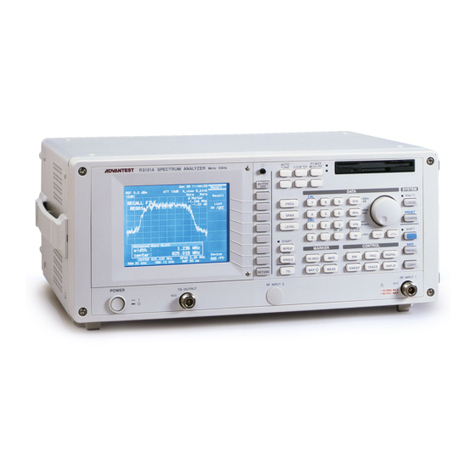
ADVANTEST R3131 Series User manual
ADVANTEST
ADVANTEST R3763B User manual
ADVANTEST
ADVANTEST R3765G Series User manual
ADVANTEST
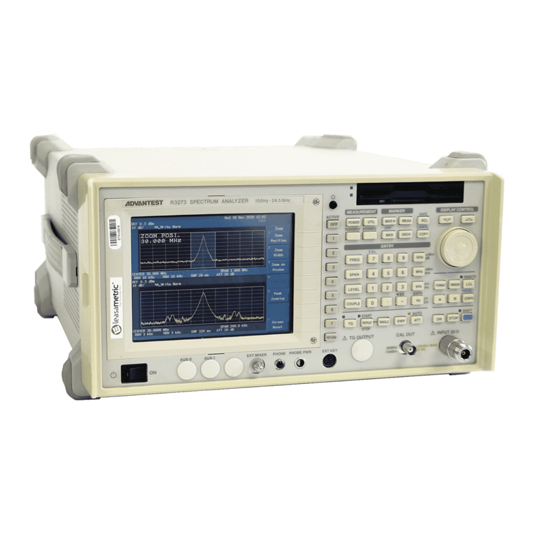
ADVANTEST R3267 series User manual
ADVANTEST
ADVANTEST R3131A User manual
ADVANTEST
ADVANTEST R3465 Series User manual

ADVANTEST
ADVANTEST R3755 Series User manual
ADVANTEST
ADVANTEST R3261C Installation manual

