Tyco T1200 Mounting instructions

EQUIPMENT: T1200
PUBLICATION: 19A-4-O
ISSUE No. & DATE: 3 06/09
© 2006 Tyco Safety Products PAGE 1 of 13
Registered Company: Thorn Security Ltd. Registered Office: Dunhams Lane Letchworth Garden City Hertfordshire SG6 1BE
TYCO T1200Fire Alarm Control Panel & Repeater
User Operation Manual
List of Contents
1. INTRODUCTION.....................................................2
2. T1200 USER OPERATION - FIRE AND FAULT
CONDITIONS.........................................................2
2.1 IF A FIRE IS DETECTED: .....................................2
2.2 TO SILENCE THE FIRE ALARM SOUNDERS: ........3
2.3 TO RESOUND THE FIRE ALARM SOUNDERS
AFTER THEY HAVE BEEN SILENCED:..................3
2.4 TO RESET THE PANEL FROM A FIRE ALARM: ....3
2.5 TO OPERATE THE FIRE ALARM SOUNDERS IN
MANUAL FIRE ALARM/MUSTER MODE:...........3
2.6 IF A FAULT IS DETECTED:..................................4
2.7 TO SILENCE THE BUZZER: ................................4
2.8 SYSTEM FAULT INDICATION:............................4
3. T1200 USER INDICATIONS ..................................5
3.1 USER INDICATIONS...........................................5
3.2 USER CONTROLS ..............................................6
4. T1200 USER CONTROLS – DISABLEMENT
AND TEST CONDITIONS.....................................7
4.1 TO DISABLE/ENABLE ANY ZONE OR ZONES. ....7
4.2 TO DISABLE/ENABLE ALL SOUNDERS. .............7
4.3 TO DISABLE/ENABLE THE FIRE OUTPUT. .........7
4.4 TO DISABLE/ENABLE THE FAULT OUTPUT. ......8
4.5 TO DISABLE/ENABLE FIRE PROTECTION
OUTPUT[S]. ......................................................8
4.6 TO SELECT/CLEAR ONE MAN ZONE TEST........9
4.7 TO SELECT/CLEAR ONE MAN SOUNDER TEST.9
4.8 TO ENABLE/DISABLE DELAY MODE ..............10
4.9 TO OVERRIDE THE DELAY MODE .................. 10
4.10 SILENCING THE ALARMS DURING THE DELAY
PERIOD: ......................................................... 10
4.11 RESOUNDING THE ALARMS AFTER 2MINUTES:
[ALARMS PREVIOUSLY SILENCED] ................. 10
4.12 TO ADJUST THE BRIGHTNESS OF THE LEDS ON
THE DISPLAY .................................................. 10
5. T1200 REPEATER PANEL USER OPERATION -
FIRE AND FAULT CONDITIONS....................10
5.1 IF A FIRE IS DETECTED:................................... 10
5.2 TO SILENCE THE FIRE ALARM SOUNDERS:...... 11
5.3 TO RESOUND THE FIRE ALARM SOUNDERS
AFTER THEY HAVE BEEN SILENCED: ............... 11
5.4 TO RESET THE PANEL &REPEATER(S)FROM A
FIRE ALARM: ................................................. 11
5.5 TO OPERATE THE FIRE ALARM SOUNDERS IN
MANUAL FIRE ALARM /MUSTER MODE: ....... 11
5.6 IF A FAULT IS DETECTED: ............................... 11
5.7 TO SILENCE THE BUZZER:.............................. 11
5.8 SYSTEM FAULT INDICATION: ......................... 11
5.9 T1200 REPEATER PANEL OPERATION [16 ZONE
VERSION SHOWN]........................................... 12
6. ROUTINE TESTING AND MAINTENANCE....13
7. USER RESPONSIBILITIES.................................13
8. T1200 ISOLATE/DE-ISOLATE/TEST MODE
SELECT FLOWCHART.....................................13
DANGER
THIS EQUIPMENT CONTAINS HAZARDOUS VOLTAGES
THAT CAN CAUSE DEATH, SERIOUS PERSONAL
INJURY, OR EQUIPMENT DAMAGE.
THIS EQUIPMENT CONTAINS NO USER SERVICEABLE
PARTS. ENSURE PANEL DOOR IS KEPT CLOSED.
REFER ALL MAINTENANCE TO SUITABLY QUALIFIED
PERSONNEL.

T1200
19A-4-O
3 06/09
PAGE 2 of 13
1. Introduction
This document contains information necessary for
operating the T1200 Marine Conventional Fire
Detection control panel.
The following supporting documentation is also
available:
•T1200 Application Guide/Sales Literature.
•T1200 Installation and Commissioning
Manual.
•T1200 Log Book.
Note: References are made throughout this
document to “Fire Protection Output” and Fire
Output”. These refer to particular outputs from the
T1200 panels and are provided for specific
purposes:
•Fire Protection Output: An output used to
activate ancillary fire protection equipment
or systems. For example, fire doors or plant
shutdown.
•Fire Output: An output used to send a
common fire warning signal to a remote
fire monitoring station.
References are also made to “Manual Fire Alarm”
and “Muster”. These relate to fire alarm sounder
operating modes which are activated manually from
the fire panel display. The panel is configurable to
one or other of the two modes.
2. T1200 User Operation - Fire and Fault
Conditions
This panel is capable of operating in two alarm
modes:
1. Standard Mode:
a. Sounder circuits can operate per zone or all
together.
b. Sounder circuits can be continuous or
pulsed.
c. Sounders (and other outputs) can be
delayed by 2 minutes.
2. Crew Alert Mode:
a. Sounder circuits can be continuous or
pulsed.
b. Two Sounder circuits always operate
without delay for any fire condition (Crew
Alert Sounders).
c. All other Sounder circuits are always
delayed by 2-minutes for a detector fire
condition.
d. Other outputs may be optionally configured
to be delayed along with the Sounders.
e. The Delay period may be extended by
silencing the immediate Sounders before
the delay ends.
A new detector fire condition may operate
all Sounders and delayed outputs
immediately or may not restart the delay
depending on the panel configuration.
In addition to these to modes, the panel may also be
configured to provide a Muster alarm signal. This
signal will override any other sounder operation.
All users should be fully aware of the particular
configuration of their system and should have
received training in the basic operation of the
system.
The following information is provided as a quick
reference guide only.
2.1 If a fire is detected:
On the T1200 Fire Alarm Panel:
oThe general Fire LED will flash and the buzzer
will sound
oThe relevant zone Fire LED will flash,
indicating the location of the fire.
oSTANDARD MODE: If the Delay is OFF
[Delay LED off]:
The Fire output and LED will operate
immediately
The Fire Alarm sounders will operate
immediately (pulsed or continuous,
zonally or together, as per configuration)
The Fire Protection output(s) will operate
immediately
oSTANDARD MODE: If the Delay is ON
[Delay LED flashing]:
The Fire output will be delayed if
configured to do so.
The Fire Alarm sounders will be delayed
if configured to do so.
The Fire Protection output will be delayed
if configured to do so.
To identify which outputs are set to delay:
Turn the Access Controls Keyswitch on
the panel door to position “1.
Press the Disable button.
The Fault/Disablement LEDs on each of
the outputs set to delay will be
illuminated.

EQUIPMENT: T1200
PUBLICATION: 19A-4-O
ISSUE No. & DATE: 3 06/09
© 2006 Tyco Safety Products PAGE 3 of 13
Registered Company: Thorn Security Ltd. Registered Office: Dunhams Lane Letchworth Garden City Hertfordshire SG6 1BE
Locate the source of the fire alarm (an
LED will be visible on the detector which
has been activated). The delay will end
after 2 minutes and all delayed outputs
will operate unless the panel is reset.
oCREW MODE: If the Delay is OFF [Delay
LED flashing, DISABLE LED off]:
The Fire output and LED will operate
immediately
The Fire Alarm sounders in the Crew
areas will operate immediately (pulsed or
continuous, as per configuration), all other
sounders will be delayed.
The Fire Protection output(s) will operate
immediately
oCREW MODE: If the Delay is ON [Delay
LED flashing, DISABLE LED on]:
The Fire output will be delayed if
configured to do so.
The Fire Alarm sounders in the Crew
areas will operate immediately (pulsed or
continuous, as per configuration), all other
sounders will be delayed.
The Fire Protection output will be delayed
if configured to do so.
To identify which outputs are set to delay:
Turn the Access Controls Keyswitch on
the panel door to position “1.
Press the Disable button.
The Fault/Disablement LEDs on each of
the outputs set to delay will be
illuminated.
Locate the source of the fire alarm (an
LED will be visible on the detector which
has been activated). The delay will end
after 2 minutes and all delayed outputs
will operate unless the Crew Sounders are
silenced before the end of the delay.
2.2 To Silence the fire alarm
sounders:
•Turn the Access Controls Keyswitch on the
panel door to position “1”.
•Press the Silence Alarms/Resound button once
only.
•The fire alarm sounders will become silent.
•The General Fire LED and the Zone Fire LED
will become steady.
•Set the Access Controls Keyswitch back to
position “0” to lock the controls.
2.3 To Resound the fire alarm
sounders after they have been silenced:
•Turn the Access Controls Keyswitch on the
panel door to position “1”.
•Press the Silence Alarms/Resound button once
only.
NOTE - IN CREW MODE:
If the Resound Alarms is operated it will
cancel any extended delay and all sounders
and outputs will operate immediately.
•Set the Access Controls Keyswitch back to
position “0” to lock the controls.
2.4 To Reset the panel from a Fire
Alarm:
•After the fire has been extinguished, turn the
Access Controls Keyswitch on the panel door
to position “1”.
•Press the Reset button (the Sounders may need
to be silenced first, depending on
configuration).
•The General Fire LED and the Zone Fire LED
will clear.
•Set the Access Controls Keyswitch back to
position “0” to lock the controls.
2.5 To operate the fire alarm
sounders in Manual Fire Alarm/Muster
Mode:
•Turn the Access Controls Keyswitch on the
panel door to position “1”.
•Press the Manual Fire Alarm/Muster button.
•The Manual Fire Alarm/Muster LED will light
and the panel buzzer will operate.
•All fire alarm sounders will operate, either
continuously or pulsed, or in muster mode i.e.
7 short, 1 long pulse, repeated..
•Press the Silence/Resound Alarm button to
silence the fire alarm sounders and clear the
Manual fire alarm/Muster LED.
•Set the Access Controls Keyswitch back to
position “0” to lock the controls.
T1200
19A-4-O
3 06/09
PAGE 4 of 13
2.6 If a fault is detected:
•The panel buzzer will sound.
•The General Fault LED will flash.
•One or more fault LEDs will flash; identifying
which element of the system is faulty.
•When the fault is corrected the fault indication
will clear automatically unless the panel is
configured to latched fault mode – in which
case, operating the Reset button will clear the
fault indication.
2.7 To Silence the Buzzer:
•Press the Silence Buzzer button.
•The Silence Buzzer button LED will light.
•The buzzer will silence.
2.8 System Fault Indication:
In the event of a complete system failure, a System
Fault will be indicated:
•The SYSTEM FAULT and GENERAL
FAULT LED illuminate. All other LEDs will
be extinguished.
•The internal buzzer will sound continuously.
Warning: The system is completely inactive
apart from the operation of Muster alarms
if configured.
User Actions:
•Determine the area affected by the fault and
decide whether special action (such as fire
patrols) are needed in that area.
•Call your service engineer immediately.
•Record the event in the system log book.

EQUIPMENT: T1200
PUBLICATION: 19A-4-O
ISSUE No. & DATE: 3 06/09
© 2006 Tyco Safety Products PAGE 5 of 13
Registered Company: Thorn Security Ltd. Registered Office: Dunhams Lane Letchworth Garden City Hertfordshire SG6 1BE
3. T1200 User Indications
This section gives an overview of the functions available to the end user.
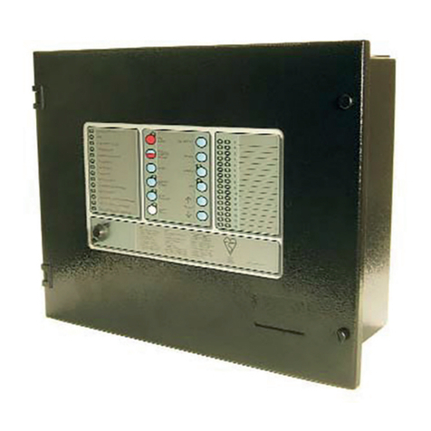
3.1 User Indications General Indicator Section
Indicator Description Indication
Colour Operating Condition
Power Supply On Green Illuminates Steady for Mains or Standby power On.
Fire Red
Flashes on any new fire alarm condition, changing to a steady indication on operation of Silence
Alarms.
Fire Output Active Red Illuminates Steady when the Fire Output is active.
General Fault Yellow Flashes for any fault condition.
Power Supply Fault Yellow Flashes for mains or standby power supply/charge fault
System Fault Yellow Illuminates Steady to indicate Microcontroller or Memory Failure.
Flashes to indicate Engineer’s Configuration Mode active.
Earth Fault Yellow Flashes for any positive or negative power supply earth fault.
Fuse Failed Yellow Flashes for any auxiliary supply fuse failure.
Repeater Fault Yellow Flashes for any Repeater fault or repeater communication fault.
Sounder Fault/Disabled Yellow Flashes for any sounder fault. Steady for sounders disabled.
Sounder Test Yellow Illuminates Steady while sounder walk test is active.
Fire Protection Fault/Disabled Yellow Flashes for a fault on the Fire Protection Output. Steady when Fire Protection Output is disabled.
Fire Output Fault/Disabled Yellow Flashes for a fault on the Fire Output. Steady when Fire Output is disabled.
Fault Output Fault/Disabled Yellow Flashes for a fault on the Fault Output. Steady when Fault Output is disabled.
1.
2.
3.
4.
5.
6.
7.
8.
9.
10.
11.
12.
13.
14.
15.
16.
01
ZONE LOCATION
FIRE
POWER SUPPLY ON
POWER SUPPLY FAULT
SYSTEM FAULT
GENERAL FAULT
EARTH FAULT
FUSE FAILED
REPEATER FAULT
FAULT OUTPUT FAULT/DISABLED
SOUNDER FAULT/DISABLED
SOUNDER TEST
FIRE PROTECTION FAULT/DISABLED
FIRE OUTPUT ACTIVE
FIRE OUTPUT FAULT/DISABLED
BUZZER
SILENCE
RESET
ENABLE
DISABLE
TEST
TEST DISPLAY
ALARMS
RESOUND
SELECT
ON/OFF
SELECT
SILENCE/
ALARM
MUSTER
FIRE
1. THE RED ZONE INDICATOR
WILL PULSE SHOWING THE
LOCATION OF THE FIRE.
2. CARRY OUT THE
REQUIRED FIRE DRILL.
3. TO SILENCE ALARMS
PRESS SILENCE ALARMS.
4. TO RESET FROM THE FIRE
CONDITION PRESS RESET.
FAULT
1. DETERMINE THE CAUSE OF
THE FAULT.
2. PRESS SILENCE BUZZER.
3. CALL YOUR SERVICE
ENGINEER.
SYSTEM FAULT
THE PANEL IS INOPERATIVE.
ARRANGE FOR ALTERNATIVE
FIRE DETECTION MEASURES.
DISABLEMENT AND TEST
1. PRESS SELECT ON/OFF.
THE LED WILL ILLUMINATE.
2. SELECT THE ZONE OR
OUTPUT USING ↑AND ↓. THE
FAULT LED WILL PULSE.
3. PRESS DISABLE OR TEST.
4. TO RE-ENABLE, SELECT
THE ZONE OR OUTPUT AND
PRESS ENABLE.
OVERRIDE
DELAY
MODEL:
T1216
C.I.E. PRODUCTION PERIOD: 1
www.tycomarine.com
EN54-2: 1997
EN54-4: 1997
KM95744
Zone Location Indications
Indicator Description Indication
Colour Operating Condition
User Generated Zone Location Text Red Flashes when zone is in a fire condition, turning to steady on operation of Silence Alarms.
User Generated Zone Location Text Yellow Flashes when zone is in a fault condition. Illuminates steady when zone is disabled or in test.
Access Controls Keyswitch:
0 – Controls Locked
1 – Controls Unlocked User Instructions

T1200
19A-4-O
3 06/09
PAGE 6 of 13
3.2 User Controls
1.
2.
3.
4.
5.
6.
7.
8.
9.
10.
11.
12.
13.
14.
15.
16.
01
ZONE LOCATION
FIRE
POWER SUPPLY ON
POWER SUPPLY FAULT
SYSTEM FAULT
GENERAL FAULT
EARTH FAULT
FUSE FAILED
REPEATER FAULT
FAULT OUTPUT FAULT/DISABLED
SOUNDER FAULT/DISABLED
SOUNDER TEST
FIRE PROTECTION FAULT/DISABLED
FIRE OUTPUT ACTIVE
FIRE OUTPUT FAULT/DISABLED
BUZZER
SILENCE
RESET
ENABLE
DISABLE
TEST
TEST DISPLAY
ALARMS
RESOUND
SELECT
ON/OFF
SELECT
SILENCE/
ALARM
MUSTER
FIRE
1. THE RED ZONE INDICATOR
WILL PULSE SHOWING THE
LOCATION OF THE FIRE.
2. CARRY OUT THE
REQUIRED FIRE DRILL.
3. TO SILENCE ALARMS
PRESS SILENCE ALARMS.
4. TO RESET FROM THE FIRE
CONDITION PRESS RESET.
FAULT
1. DETERMINE THE CAUSE OF
THE FAULT.
2. PRESS SILENCE BUZZER.
3. CALL YOUR SERVICE
ENGINEER.
SYSTEM FAULT
THE PANEL IS INOPERATIVE.
ARRANGE FOR ALTERNATIVE
FIRE DETECTION MEASURES.
DISABLEMENT AND TEST
1. PRESS SELECT ON/OFF.
THE LED WILL ILLUMINATE.
2. SELECT THE ZONE OR
OUTPUT USING ↑AND ↓. THE
FAULT LED WILL PULSE.
3. PRESS DISABLE OR TEST.
4. TO RE-ENABLE, SELECT
THE ZONE OR OUTPUT AND
PRESS ENABLE.
OVERRIDE
DELAY
MODEL:
T1216
C.I.E. PRODUCTION PERIOD: 1
www.tycomarine.com
EN54-2: 1997
EN54-4: 1997
KM95744
Switch
Description Functionality Button Availability
Manual Fire Alarm
or Muster
[Configuration
option]
Manual Fire Alarm: Operates all sounders continuously and lights the Manual fire
alarm/Muster LED adjacent the button until the silence button is operated
Muster: Operate all sounders in the Muster mode and lights Muster LED
When controls are unlocked
Silence/Resound
Alarms
Following a fire alarm condition, 1st operation stops sounders. The General Fire
LED and the Zonal fire LED will change from flashing to steady. 2nd operation
restarts the previously silenced sounders
When controls are unlocked
Reset Clears the panel display, resets the zones, outputs and operates the reset relay.
When controls are unlocked
and [if silence before reset is configured]
alarms silence switch has been operated.
Silence Buzzer Press to stop the buzzer sounding in fire or fault conditions.
When controls are locked or unlocked
Delay Override Overrides the delay when delay is running, turning the delay mode and the LED
off. All delayed outputs will operate immediately.
When the panel is in the fire condition and
the delay is running.
Select On/Off Enables the User select feature for selection of zones or outputs via Select ↑
Select ↓for disablement/re-enablement. When controls are unlocked
Test Display Press to illuminate all LEDs on the display and operate the buzzer. All indications
remain active for approx 5 seconds after button release. When controls are locked or unlocked
Enable Press to clear the disablement or test condition on a zone or output selected via
the User Select feature.
When controls are unlocked, the Select
switch has been operated and a zone or
output has been selected
1] Press to disable a zone or output selected via the User Select feature. LED is lit
whilst any disablement is active 1] As above.
Disable
2] Press to view delay configuration of sounders, Fire and Fire Protection outputs. 2] When controls are unlocked.
Test Press to initiate the One Man Test on sounders or zones as selected via the User
Select feature. LED lit whilst test mode is active. As above.
1] Used to scroll the cursor indication through the zone and output fault LEDs on
the display to select a zone or output for disablement, or test. [LED illuminated
when Select Mode is active]
1] When controls are unlocked and the
Select switch has been operated.
Select ↑Select ↓
2] Used to adjust the brightness of the display LEDs [Press Test Display and ↑to
increase or Test Display and ↓to decrease] 2] When controls are unlocked
Access Controls Keyswitch:
0 – Controls Locked
1 – Controls Unlocked

EQUIPMENT: T1200
PUBLICATION: 19A-4-O
ISSUE No. & DATE: 3 06/09
© 2006 Tyco Safety Products PAGE 7 of 13
Registered Company: Thorn Security Ltd. Registered Office: Dunhams Lane Letchworth Garden City Hertfordshire SG6 1BE
4. T1200 User Controls – Disablement
and Test Conditions.
4.1 To Disable/Enable any Zone or
Zones.
•To Access disable/enable mode:
oTurn the Access Controls Keyswitch on the
panel door to position “1”.
oPress the Select On/Off button to enter the
Select Mode.
oThe Select On LED will light.
oThe cursor indication will pulse the yellow
Zone 1 fault LED.
•To select the zone:
Use the Select ↓button to move the cursor
indication down through the fault LEDs until it
pulses on the required zone. [The Select ↑
button moves the cursor up].
•To disable the selected zone:
oPress the Disable button to disable the
selected zone.
oThe zone fault/disabled LED will change to
the “On-flash” indication while the cursor
is on it, changing to steady if the cursor is
moved on.
oThe general Disablement LED will light.
•To enable the selected zone:
oPress the Enable button to enable the
selected zone.
oThe zone fault/disabled LED will change to
the “Off-flash” indication while the cursor
is on it, changing to off if the cursor is
moved on.
oThe general Disablement LED will be
cleared if no other disablements are present.
•To quit the disable/enable mode:
oTo exit the Select Mode, press the Select
On/Off button.
oThe Select On LED will clear.
oThe cursor indication will clear.
oSet the Access Controls Keyswitch back to
position “0” to lock the controls.
4.2 To Disable/Enable all Sounders.
Note: Sounder disablement will be overridden by
Muster Alarm operation.
•To Access disable/enable mode:
oTurn the Access Controls Keyswitch on the
panel door to position “1”.
oPress the Select On/Off button to enter the
Select Mode.
oThe Select On LED will light.
oThe cursor indication will pulse the yellow
Zone 1 fault LED.
•To select the sounders:
Use the Select ↑button to move the pulsed
cursor indication up through the fault LEDs
until it pulses the Sounder Fault/Disabled and
Sounder Test LEDs. [The Select ↓button
moves the cursor down].
•To disable the sounders:
oPress the Disable button to disable the
sounders.
oThe Sounder Fault/Disabled LED will
change to the “On-flash” indication while
the cursor is on it, changing to steady if the
cursor is moved.
oThe general Disablement LED will light.
•To enable the sounders:
oPress the Enable button to enable the
sounders.
oThe Sounder Fault/Disabled LED will
change to the “Off-flash” indication while
the cursor is on it, changing to off if the
cursor is moved on.
oThe general Disablement LED will be
cleared if no other disablements are present.
•To quit the disable/enable mode:
oTo exit the Select Mode, press the Select
On/Off button.
oThe Select On LED will clear.
oThe cursor indication will clear.
oSet the Access Controls Keyswitch back to
position “0” to lock the controls.
4.3 To Disable/Enable the Fire
Output.
•To Access disable/enable mode:
oTurn the Access Controls Keyswitch on the
panel door to position “1”.
oPress the Select On/Off button to enter the
Select Mode.
oThe Select On LED will light.

T1200
19A-4-O
3 06/09
PAGE 8 of 13
oThe cursor indication will pulse the yellow
Zone 1 fault LED.
•To select the Fire Output:
Use the Select ↑button to move the pulsed
cursor indication up through the fault LEDs
until it pulses the Fire Output Fault/Disabled
LED. [The Select ↓button moves the cursor
down].
•To disable the Fire Output:
oPress the Disable button to disable the Fire
Output.
oThe Fire Output Fault/Disabled LED will
change to the “On-flash” indication while
the cursor is on it, changing to steady if the
cursor is moved.
oThe general Disablement LED will light.
•To enable the Fire Output:
oPress the Enable button to enable the Fire
Output.
oThe Fire Output Fault/Disabled LED will
change to the “Off-flash” indication while
the cursor is on it, changing to off if the
cursor is moved on.
oThe general Disablement LED will be
cleared if no other disablements are present.
•To quit the disable/enable mode:
oTo exit the Select Mode, press the Select
On/Off button.
oThe Select On LED will clear.
oThe cursor indication will clear.
oSet the Access Controls Keyswitch back to
position “0” to lock the controls.
4.4 To Disable/Enable the Fault
Output.
•To Access disable/enable mode:
oTurn the Access Controls Keyswitch on the
panel door to position “1”.
oPress the Select On/Off button to enter the
Select Mode.
oThe Select On LED will light.
oThe cursor indication will pulse the yellow
Zone 1 fault LED.
•To select the Fault Output:
oUse the Select ↑button to move the pulsed
cursor indication up through the fault LEDs
until it pulses the Fault Output
Fault/Disabled LED. [The Select ↓button
moves the cursor down].
•To disable the Fault Output:
oPress the Disable button to disable the Fault
Output.
oThe Fault Fault/Disabled LED will change
to the “On-flash” indication while the
cursor is on it, changing to steady if the
cursor is moved.
oThe general Disablement LED will light.
•To enable the Fault Output:
oPress the Enable button to enable the Fault
Output.
oThe Fault Output Fault/Disabled LED will
change to the “Off-flash” indication while
the cursor is on it, changing to off if the
cursor is moved on.
oThe general Disablement LED will be
cleared if no other disablements are present.
•To quit the disable/enable mode:
oTo exit the Select Mode, press the Select
On/Off button.
oThe Select On LED will clear.
oThe cursor indication will clear.
oSet the Access Controls Keyswitch back to
position “0” to lock the controls.
4.5 To Disable/Enable Fire Protection
Output[s].
•To Access disable/enable mode:
oTurn the Access Controls Keyswitch on the
panel door to position “1”.
oPress the Select On/Off button to enter the
Select Mode.
oThe Select On LED will light.
oThe cursor indication will pulse the yellow
Zone 1 fault LED.
•To select the Fire Protection Output:
Use the Select ↑button to move the pulsed
cursor indication up through the fault LEDs
until it pulses the Fire Protection
Fault/Disabled LED. [The Select ↓button
moves the cursor down].
•To disable the Fire Protection Output:
oPress the Disable button to disable the Fire
Protection Output.

EQUIPMENT: T1200
PUBLICATION: 19A-4-O
ISSUE No. & DATE: 3 06/09
© 2006 Tyco Safety Products PAGE 9 of 13
Registered Company: Thorn Security Ltd. Registered Office: Dunhams Lane Letchworth Garden City Hertfordshire SG6 1BE
oThe Fire Protection Fault/Disabled LED
will change to the “On-flash” indication
while the cursor is on it, changing to steady
if the cursor is moved.
oThe general Disablement LED will light.
•To enable the Fire Protection Output:
oPress the Enable button to enable the Fire
Protection Output.
oThe Fire Protection Fault/Disabled LED
will change to the “Off-flash” indication
while the cursor is on it, changing to off if
the cursor is moved on.
oThe general Disablement LED will be
cleared if no other disablements are present.
•To quit the disable/enable mode:
oTo exit the Select Mode, press the Select
On/Off button.
oThe Select On LED will clear.
oThe cursor indication will clear.
oSet the Access Controls Keyswitch back to
position “0” to lock the controls.
4.6 To Select/Clear One Man Zone
Test.
•To access test selection mode:
oTurn the Access Controls Keyswitch on the
panel door to position “1”.
oPress the Select On/Off button to enter the
Select Mode.
oThe Select On LED will light.
oThe cursor indication will pulse the yellow
Zone 1 fault LED.
•To select the zone to be tested:
Use the Select ↓button to move the pulsed
cursor indication down through the fault LEDs
until it pulses on the required zone. [The Select
↑button moves the cursor up].
•To apply the test mode to the selected zone:
oPress the Test button to activate the test
condition on the selected zone.
oThe zone fault/disabled LED will change to
the “On-flash” indication while the cursor
is on it, changing to steady if the cursor is
moved on.
oThe general Test LED will light.
•To clear the test mode on the selected zone:
oPress the Test button again or press the
Enable button to clear the test condition
enabling normal operation of the selected
zone.
oThe zone fault/disabled LED will change to
the “Off-flash” indication while the cursor
is on it, changing to off if the cursor is
moved on.
oThe general Test LED will be cleared if no
other circuits are in the test condition.
•To quit the zone test selection mode:
oTo exit the Select Mode, press the Select
On/Off button.
oThe Select On LED will clear.
oThe cursor indication will clear.
oSet the Access Controls Keyswitch back to
position “0” to lock the controls.
4.7 To Select/Clear One Man Sounder
Test.
•To access test selection mode:
oTurn the Access Controls Keyswitch on the
panel door to position “1”.
oPress the Select On/Off button to enter the
Select Mode.
oThe Select On LED will light.
oThe cursor indication will pulse the yellow
Zone 1 fault LED.
•To select the sounders:
Use the Select ↑button to move the pulsed
cursor indication up through the fault LEDs
until it pulses the Sounder Fault/Disabled and
Sounder Test LEDs. [The Select ↓button
moves the cursor down].
•To activate the sounder test:
oPress the Test button to start the sounder
test.
oThe Sounder Test LED will change to the
“On-flash” indication while the cursor is on
it, changing to steady if the cursor is
moved.
oThe general Test LED will light.
oThe sounders will operate for 2 seconds
every 15 seconds until the test mode is
switched off.

T1200
19A-4-O
3 06/09
PAGE 10 of 13
•To terminate the sounder test:
oPress the Test button again or press the
Enable button to clear the test condition
enabling normal operation of sounders.
oThe sounders will silence.
oThe Sounder Test LED will change to the
“Off-flash” indication while the cursor is on
it, changing to off if the cursor is moved on.
oThe general Test LED will be cleared if no
other circuits are in the test condition.
•To quit test selection mode:
oTo exit the Select Mode, press the Select
On/Off button.
oThe Select On LED will clear.
oThe cursor indication will clear.
oSet the Access Controls Keyswitch back to
position “0” to lock the controls.
4.8 To Enable/Disable Delay Mode
The delay mode is automatically enabled and the
Delay LED will be illuminated when any output is
configured to be delayed.
NOTE: In Crew Mode, Crew Sounders cannot be
delayed and all other sounders are always delayed.
The Delay LED is NOT illuminated if no other
outputs are configured to be delayed.
4.9 To Override the Delay Mode
•When the Delay is running:
oThe Delay On/Off LED will flash.
oThe general Fire and zone fire LEDs will
flash.
oThe panel buzzer will operate.
•Press the Delay Override button while the
Delay LED is flashing to override the delay
allowing all delayed outputs to operate
immediately.
•Operation of a Manual Call Point will also
override the delay.
4.10 Silencing the Alarms during the
Delay Period:
•Turn the Access Controls Keyswitch on the
panel door to position “1”.
•Press the Silence Alarms/Resound button.
oThe General Fire LED and the Zone Fire
LED become steady.
oStandard Mode: The sounders will not
operate after the delay has timed out. All
other delayed outputs will operate after the
delay ends.
oCrew Mode: The sounders crew sounders
will silence, all other sounders will not
operate and any delayed outputs will not
operate. The delay will be stopped.
•Set the Access Controls Keyswitch back to
position “0” to lock the controls.
4.11 Resounding the Alarms after 2
minutes: [Alarms previously silenced]
•Turn the Access Controls Keyswitch on the
panel door to position “1”.
•Press the Silence Alarms/Resound button.
oThe General Fire LED will flash.
oStandard Mode: The silenced sounders
operate.
oCrew mode: All sounders & delayed
outputs operate immediately.
•Set the Access Controls Keyswitch back to
position “0” to lock the controls.
4.12 To adjust the brightness of the
LEDs on the display
•Turn the Access Controls Keyswitch on the
panel door to position “1”.
•Press Test Display and ↑to increase brightness
or Test Display and ↓to decrease.
5. T1200 Repeater Panel User Operation
- Fire and Fault Conditions
5.1 If a fire is detected:
•On the T1200 Repeater Panel:
oThe general Fire LED will flash and the
buzzer will sound
oThe relevant zone Fire LED will flash,
indicating the location of the fire.
oThe Delay LED will flash if the 2-minute
delay is running.
•Locate the source of the fire alarm (an LED
will be visible on the detector which has been
activated).

EQUIPMENT: T1200
PUBLICATION: 19A-4-O
ISSUE No. & DATE: 3 06/09
© 2006 Tyco Safety Products PAGE 11 of 13
Registered Company: Thorn Security Ltd. Registered Office: Dunhams Lane Letchworth Garden City Hertfordshire SG6 1BE
5.2 To Silence the fire alarm
sounders:
•Turn the Access Controls Keyswitch on the
repeater door to position “1”.
•Press the Silence Alarms/Resound button once
only.
•The fire alarm sounders will become silent.
•The General Fire LED and the Zone Fire LED
will become steady.
•Set the Access Controls Keyswitch back to
position “0” to lock the controls.
5.3 To Resound the fire alarm
sounders after they have been silenced:
•Turn the Access Controls Keyswitch on
the repeater door to position “1”.
•Press the Silence Alarms/Resound button
once only.
•Set the Access Controls Keyswitch back to
position “0” to lock the controls.
5.4 To Reset the panel & repeater(s)
from a Fire Alarm:
•After the fire has been extinguished, turn the
Access Controls Keyswitch on the repeater
door to position “1”.
•Press the Reset button (the Sounders may need
to be silenced first, depending on
configuration).
•The General Fire LED and the Zone Fire LED
will clear.
•Set the Access Controls Keyswitch back to
position “0” to lock the controls.
5.5 To operate the fire alarm
sounders in Manual Fire Alarm /Muster
Mode:
•Turn the Access Controls Keyswitch on the
repeater door to position “1”.
•Press the Manual fire alarm/Muster button.
•The Manual fire alarm/Muster LED will light
and the repeater buzzer will operate.
•All fire alarm sounders will operate.
•Press the Silence/Resound Alarm button to
silence the fire alarm sounders and clear the
Manual fire alarm/Muster LED.
•Set the Access Controls Keyswitch back to
position “0” to lock the controls.
5.6 If a fault is detected:
•The panel buzzer will sound.
•The General Fault LED will flash.
•One or more fault LEDs will flash; identifying
which element of the system is faulty.
•When the fault is corrected the fault indication
will clear automatically unless the panel is
configured to latched fault mode – in which
case, operating the Reset button will clear the
fault indication.
5.7 To Silence the Buzzer:
•Press the Silence Buzzer button.
•The Silence Buzzer button LED will light.
•The buzzer will silence.
5.8 System Fault Indication:
In the event of a complete repeater failure, a System
Fault will be indicated on the repeater:
•The SYSTEM FAULT and GENERAL
FAULT LED illuminate. All other LEDs will
be extinguished.
•The internal buzzer will sound continuously.
Warning: The Repeater is completely inactive
apart from the operation of Muster alarms if
configured.
User Actions:
•Silence the buzzer on the panel.
•Call your service engineer immediately.
•Record the event in the system log book.

T1200
19A-4-O
3 06/09
PAGE 12 of 13
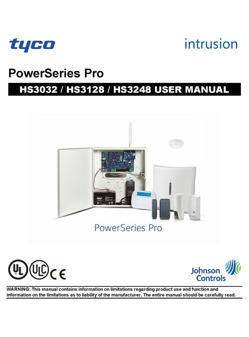
5.9T1200 Repeater Panel Operation [16 zone version shown]
General Indicator Section
Indicator Description Indication
Colour Operating Condition
Power Supply On Green Illuminates Steady for Mains or Standby power On.
Fire Red Flashes on any new fire alarm condition, changing to a steady indication on operation of Silence Alarms.
Fire Output Active Red Illuminates Steady when the Fire Output is active.
General Fault Yellow Flashes for any fault condition.
Power Supply Fault Yellow Flashes for mains or standby power supply/charge fault
System Fault Yellow Illuminates Steady to indicate Microcontroller or Memory Failure.
General Test Yellow Illuminated when Test Mode is active
General Disablement Yellow Illuminated while any disablement is active
Communication Fault Yellow Flashes for a repeater communication fault
Sounder Fault/Disabled Yellow Flashes for any sounder fault. Steady for sounders disabled.
Sounder Test Yellow Illuminates Steady while sounder walk test is active.
Fire Protection Fault/Disabled Yellow Flashes for a fault on the Fire Protection Output. Steady when Fire Protection Output is disabled.
Fire Output Fault/Disabled Yellow Flashes for a fault on the Fire Output. Steady when Fire Output is disabled.
Fault Output Fault/Disabled Yellow Flashes for a fault on the Fault Output. Steady when Fault Output is disabled.
1.
2.
3.
4.
5.
6.
7.
8.
9.
10.
11.
12.
13.
14.
15.
16.
01
ZONE LOCATION
FIRE
POWER SUPPLY ON
POWER SUPPLY FAULT
SYSTEM FAULT
GENERAL FAULT
GENERAL TEST
GENERAL DISABLEMENT
COMMUNICATION FAULT
FAULT OUTPUT FAULT/DISABLED
SOUNDER FAULT/DISABLED
SOUNDER TEST
FIRE PROTECTION FAULT/DISABLED
FIRE OUTPUT ACTIVE
FIRE OUTPUT FAULT/DISABLED
BUZZER
SILENCE
RESET
ALARMS
RESOUND
SILENCE/
TEST DISPLAY
ALARM
MUSTER
FIRE
1. THE RED ZONE INDICATOR
WILL PULSE SHOWING THE
LOCATION OF THE FIRE.
2. CARRY OUT THE
REQUIRED FIRE DRILL.
3. TO SILENCE ALARMS
PRESS SILENCE ALARMS.
4. TO RESET FROM THE FIRE
CONDITION PRESS RESET.
FAULT
1. DETERMINE THE CAUSE OF
THE FAULT.
2. PRESS SILENCE BUZZER.
3. CALL YOUR SERVICE
ENGINEER.
SYSTEM FAULT
THE PANEL IS INOPERATIVE.
ARRANGE FOR ALTERNATIVE
FIRE DETECTION MEASURES.
OVERRIDE
DELAY
MODEL:
T1204DC
C.I.E. PRODUCTION PERIOD: 1
www.tycomarine.com
EN54-2: 1997
EN54-4: 1997
KM95744
User Control Buttons
Switch
Description Functionality Button Availability
Manual Fire
Alarm or Muster
[Set at Panel]
1] Manual Fire Alarm: Operates all sounders continuously and lights the Manual fire
alarm/Muster LED adjacent the button until the silence button is operated
2] Muster: Operate all sounders in the Muster mode until the silence button is operated
When controls are unlocked
Silence/Resound
Alarms
Following a fire alarm condition, 1st operation stops sounders. The General Fire LED
and the Zonal fire LED will change from flashing to steady. 2nd operation restarts the
previously silenced sounders
When controls are unlocked
Reset Clears the panel display, resets the zones, outputs and operates the reset relay. When controls are unlocked and [optionally]
alarms have been silenced.
Silence Buzzer Press to stop the buzzer sounding in fire or fault conditions. When controls are locked or unlocked
Delay Override Overrides the delay when delay is running, turning the delay mode and the LED off. All
delayed outputs will operate immediately.
When the panel is in the fire condition and
the delay is running.
Test Display Press to illuminate all LEDs on the display and operate the buzzer for approx 5 seconds
after button release. Press again within 5 seconds to toggle the LED brightness. When controls are locked or unlocked
Zone
Indications
User
Instructions
Access Controls Keyswitch:
0 – Controls Locked
1 – Controls Unlocked
User Controls
[See below]

EQUIPMENT: T1200
PUBLICATION: 19A-4-O
ISSUE No. & DATE: 3 06/09
© 2006 Tyco Safety Products PAGE 13 of 13
Registered Company: Thorn Security Ltd. Registered Office: Dunhams Lane Letchworth Garden City Hertfordshire SG6 1BE
6. Routine Testing and maintenance
See T1200 Log Book for details.
7. User responsibilities
See T1200 Log Book for details
8. T1200 Isolate/De-Isolate/Test Mode Select Flowchart
CURSOR Sequence:
Start
T1200 Panel
Controls not Enabled
Turn ACCESS
CONTROLS keyswitch
to ‘1’
T1200 Panel
Controls Enabled
Turn ACCESS
CONTROLS keyswitch
to ‘1’
Press SELECT ON/OFF
button
T1200 Panel
SELECT mode active,
Select ON/OFF LED
illuminated
T1200 Panel
SELECT cursor flashes
zone 1 Fault LED
Press ENABLE button Press DISABLE button Press TEST button Press SELECT ON/OFF
button
Press SELECT
button Press SELECT
button
Zone 1 Fault LED
Zone 2 Fault LED
Zone n Fault LED (n=4,16 or 32
depending on panel)
Sounder Fault/Disabled & Test LEDs
Fire Protection Fault/Disabled LED
Fire Routing Fault/Disabled LED
Fault Routing Fault/Disabled LED
T1200 Panel
SELECT cursor moves
to next LED
T1200 Panel
SELECT cursor moves
to previous LED
T1200 Panel
Selected Circuit returned to
normal operation.
LED pulses ‘OFF/flash’
(changes to OFF when cursor
is removed)
T1200 Panel
Selected Circuit Disabled.
LED pulses ‘ON/flash’
(changes to ON when cursor is
removed)
T1200 Panel
Selected Circuit in Test mode.
If Zone circuit then Zone Fault
LED pulses ‘ON/flash’
(changes to ON when cursor is
removed).
If Sounders then Sounder Test
LED is ON.
T1200 Panel
SELECT mode inactive.
SELECT cursor clears.
SELECT LED clears.
Table of contents
Other Tyco Control Panel manuals

Tyco
Tyco RAPID RESPONSE RCP-1 User manual

Tyco
Tyco MC-2 User manual

Tyco
Tyco AutoPulse Z-20 User manual

Tyco
Tyco RAPID RESPONSE RCP-1 User manual

Tyco
Tyco Bentel Security ABSOLUTA Instruction manual

Tyco
Tyco PowerSeries Pro HS3032 User manual

Tyco
Tyco T1200-C Series User guide

Tyco
Tyco AutoPulse Z-10 User manual

Tyco
Tyco DSG Touch SCW9067 User manual